Furuno FA-150 Isntallation Manual
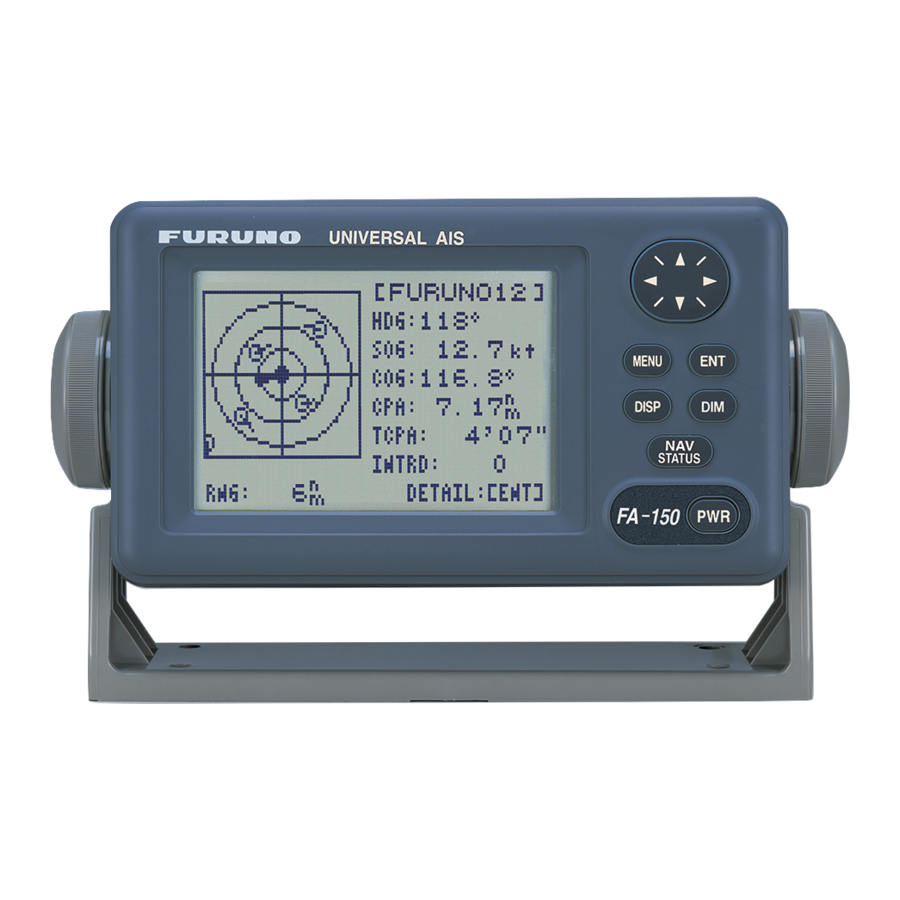
Uais transponder
Hide thumbs
Also See for FA-150:
- Installation manual (216 pages) ,
- Operator's manual (128 pages) ,
- Installation manual (52 pages)
Table of Contents
Advertisement
Quick Links
Advertisement
Table of Contents

Related Manuals for Furuno FA-150


Summary of Contents for Furuno FA-150
- Page 1 UAIS TRANSPONDER FA-150 PRINTED IN JAPAN...
- Page 2 *00015008302* *00015008302* *00015008302* *00015008302* ( ( TATA TATA ) ) FA-150 FA-150 * 0 0 0 1 5 0 0 8 3 0 2 * * 0 0 0 1 5 0 0 8 3 0 2 * *IME44310C10* *IME44310C10*...
- Page 3 SAFETY INSTRUCTIONS CAUTION WARNING ELECTRICAL SHOCK HAZARD Observe the following compass safe Do not open the equipment distances to prevent interference to a unless totally familiar with magnetic compass: electrical circuits and service manual. Standard Steering compass compass Only qualified personnel FA-1501 should work inside the 1.2 m...
-
Page 4: Table Of Contents
TABLE OF CONTENTS SYSTEM CONFIGURATION................iii EQUIPMENT LISTS ..................... iv 1. MOUNTING ....................... 1 1.1 Antenna Units ........................1 1.1.1 GPS antenna unit ....................1 1.1.2 VHF antenna ......................3 1.1.3 GPS/VHF combined antenna ................5 1.2 Monitor Unit ........................8 1.3 UAIS Transponder ......................10 1.4 Power Supply (option) ....................11 1.5 Pilot Plug (option) ......................11 2. -
Page 5: System Configuration
GPA-017S GVA-100 Distributor unit MONITOR UNIT DB-1 FA-1502 UNIVERSAL AIS MENU DISP STATUS FA-150 12-24 VDC UAIS TRANSPONDER FA-1501 External display, NAVNET2, Pilot plug unit Sensor Alarm system PC, BEACON RECEIVER Power suppy PR-240-CE : Standard : Option... -
Page 6: Equipment Lists
EQUIPMENT LISTS Standard supply Name Type Code no. Remarks UAIS Transponder FA-1501 Monitor Unit FA-1502 GSC-001 GPS Antenna Select one. GPA-017S GPS/VHF Combined Antenna GVA-100 MJ-A10SPF0012-050 000-150-216 Cable for FA-1501 CP24-00501 005-955-550 For FA-1501 For FA-1502 CP24-00400 000-041-980 CP14-06001 & Cable MJ-A3SPF0013-035 Installation Materials CP24-00101... -
Page 7: Mounting
1. MOUNTING 1.1 Antenna Units 1.1.1 GPS antenna unit Install the GPS antenna unit referring to the drawing on page D-1 at the back of this manual. When selecting a mounting location for the antenna, keep in mind the following points. •... - Page 8 How to attach the connector N-P-8DFB for cable 8D-FB-CV Dimensions in millimeters. Outer Sheath Armor Inner Sheath Shield Remove outer sheath and armor by the dimensions shown left. Expose inner sheath and shield by the dimensions shown left. Cover with heat-shrink tubing and heat. Cut off insulator and core by 10mm.
-
Page 9: Vhf Antenna
• Install the VHF whip antenna referring to the outline drawing at the back of this manual. Separate this antenna from other VHF radiotelephone antennas as shown on the next page to prevent interference to the FA-150. - Page 10 Horizontal separation distance Other VHF whip antenna Whip antenna for AIS (GPS/VHF combined antenna) More than 10 m Vertical separation distance More than 2.8 m More than 0.5 m • When coaxial cable RG-10U/Y (shipyard supply) is used, attach the coaxial plug M-P-7 (dockyard supply) as shown on the next page.
-
Page 11: Gps/Vhf Combined Antenna
How to attach the plug M-P-7 Lay the coaxial cable and attach an M-type plug (if necessary) to the cable as follows. 30 mm 1. Remove the sheath by 30 mm. Sheath 5 mm 2. Bare 23 mm of the center conductor. Trim 2 mm braided shield by 5 mm and tin. - Page 12 Mounting procedure 1. Dismount the bottom cover, cut the cable-tie inside the unit and take out the coaxial connector attached to the combined box. 2. Loosen four screws to loosen whip antenna fixture and pull out the coaxial connector coming from the combined box through the hole in the whip antenna fixture.
- Page 13 The top of the stanchion comes into contact with the flange. Stanchion Installing distributor unit DB-1 The length of the cable between the distributor unit and transponder unit is 1 m so locate the distributor unit within 1 m from the transponder unit. Fix the distributor unit on the bulkhead, facing the cable entrance downward. Remove the lid of the distributor unit and secure the unit with two self-tapping screws.
-
Page 14: Monitor Unit
1.2 Monitor Unit The monitor unit can be installed on a desktop or flush mounted in a panel. Install it on the chart table or near the steering place, referring to the outline drawing. When selecting a mounting location for the monitor unit, keep the following in mind: •... - Page 15 F type Use the optional flush mount kit OP20-29. Name Type Code No. Cosmetic panel 20-016-1051 100-251-370 Self-tapping screw 5X20 000-802-840 Hexagon-head bolt M6X12 000-862-127 Spring washer 000-864-260 1. Prepare a cutout in the mounting location whose dimensions are 183 (W) X 92 (H) mm.
-
Page 16: Uais Transponder
1.3 UAIS Transponder Mount the transponder, where it is protected from rain and water splash. This unit can be installed on a bulkhead. Install it, referring to the outline drawing. When selecting a mounting location for the transponder, keep the following in mind: •... -
Page 17: Power Supply (Option)
1.4 Power Supply (option) When selecting a mounting location for the unit, keep the following in mind: • Keep the unit out away from areas subject to water splash. • Locate the unit away from exhaust pipes and vents. • The mounting location should be well ventilated. •... -
Page 18: Wiring
2. WIRING 2.1 Connection Connect the equipment, referring to the interconnection diagram at the back this manual. GPS Antenna GPS/VHF Conbined GSC-001 or Antenna GVA-100 GPS-017S 150M-W2VN or FAB-151D Either one 0.6 m Distributor unit 0.8 m DB-1 RG-10U/Y Attached to Distributor RG-10U/Y (approx. - Page 19 EXT ALM: Connect ship's alarm system. DISP: Connect the monitor unit. COM1 COM2 DC (-) COM3 COM4 DC (+) COM5 COM6 Internal ports of the Transponder COM1: Long range communication device (Inmarsat C, etc.) or External display (Radar, ECDIS, Pilot plug) COM2 &...
- Page 20 *: Waterproofing connectors Wrap connector with vulcanizing tape and then vinyl tape. Bind the tape end with a cable-tie. Waterproofing connector **: DPYC-2.5, TTYCS-1Q and TTYCS-4 are Japan Industry Standard cables. Use them or the equivalents. DPYC-2.5 TTYCS-1Q (Four core twisted) Armor Armor Sheath...
- Page 21 Cable connection at transponder Fabrication of cables TTYCS-4 and TTYCS-1Q Shield Remove paint by 50 mm. Cut vinyl sheath. L: Depends on equipment connected. Measure at the transponder. Expose core and fold back shield onto cable. Vinyl tape Lay in clamp where paint was removed. Connection Wiring for WAGO connector Press downward. Terminal opener Wire WAGO connector Twist Procedures 1.
- Page 22 Fabrication of power cable DPYC-2.5 50 mm Vinyl sheath Armor 6 to7 mm 40 mm: Peel paint. Taping Clamp here by cable clamp.
-
Page 23: Changing Ship's Mains Specifications
Changing Ship’s Mains Specifications The power supply PR-240-CE is shipped ready for connection to a 200-230 VAC ship’s mains. If the ship’s mains is 100 VAC – 115 VAC, change the tap connection and terminal board connection as below. Attach label supplied as accessories to the punch mark on the front panel according to the ship’s mains. -
Page 24: Setting And Adjustment
The following password entry window appears. [ENTER PASSWORD] Password entry window 3. Enter the password. The INITIAL SETTINGS window appears. Note that the password is known by only the FURUNO dealer. [INITIAL SETTINGS] SET MMSI SET MMSI SET INT ANT POS. - Page 25 4. SET MMSI is selected; press the [ENT] key to display the SET MMSI window. [SET MMSI] MMSI: 000000000 IMO NO: 000000000 NAME: C. SIN: QUIT [MENU] SET MMSI window 5. MMSI is selected; press the [ENT] key. By using the cursor pad, enter ship’s MMSI (Maritime Mobile Service Identity) in nine digits.
-
Page 26: Setting Gps Antenna Position
(Data entry) 3. Press the [ENT] key again. 4. Enter distance for location “A” of FA-150 GPS antenna by using the cursor pad and press the [ENT] key. A: Distance from bow to GPS antenna position, setting range: 0-511 m 5. -
Page 27: Setting Ship Type
3.3 Setting Ship Type 1. In the INITIAL SETTINGS window, press the ▲ or ▼ key to choose the SET SHIP TYPE and press the [ENT] key. [SET SHIP TYPE] TYPE NO : * * * * TYPE DETAIL * * * * NOT AVAILABLE 2. - Page 28 If you choose COM1 for example, do as follows. 4. Press the [ENT] key to display the COM1 setting window. [SET COM1] MODE : LONG RANGE SPEED: IEC 61162-2 QUIT [MENU] 5. Press the [ENT] key again to display the MODE setting window. [SET COM1] MODE : LONG RANGE...
- Page 29 The table below shows the ports and corresponding items to be set. Port and data format/data transmission rate Port External device Format/Rate (MODE) (SPEED) LONG RANGE IEC61162-1 IEC61162-2 COM1 EXT DISPLAY IEC61162-1 IEC61162-2 DISABLE EXT DISPLAY IEC61162-1 IEC61162-2 MONITOR IEC61162-1 (No use) COM2 IEC61162-2 HI LEVEL IF...
- Page 30 The table below shows the ports and corresponding items to be set. Port and data format/data transmission rate Port External device Format/Rate (MODE) (SPEED) LONG RANGE IEC61162-1 IEC61162-2 COM1 EXT DISPLAY IEC61162-1 IEC61162-2 DISABLE EXT DISPLAY IEC61162-1 IEC61162-2 MONITOR IEC61162-1 (No use) COM2 IEC61162-2 HI LEVEL IF...
-
Page 31: Attaching Lan Kit (Option)
4. ATTACHING LAN KIT (OPTION) The LAN kit configures network via TCP/IP protocol Name: LAN kit Type: OP24-8 Code no.: 005-956-020 Name Code no. Remark 1 NET100 board 008-535-840 03P9332 2 Hex. spacer 000-801-678 Attaching 1. Dismount the bottom cover. 2. - Page 32 Setting LAN port 1. Press the [MENU] key, choose INITIAL SETTING, enter password, choose SET I/O PORT and press the [ENT] key to show the SET I/O PORT sub menu. 2. Press ▲ or ▼ to choose SET LAN PORT and press the [ENT] key. [SET LAN PORT] MODE : STANDARD IP ADDRESS...
-
Page 33: Iec61162-1/2 Data Sentences
5. IEC 61162-1/2 DATA SENTENCES IEC 61162-1/2 format data is input or output from the data port COM1-COM6. The table below shows the input/output data specifications. Transponder Port Menu setting Input/Output Data format IEC61162-2 (38.4kbps) / LONG RANGE Input/Output* IEC61162-1 (4800bps) COM1 IEC61162-2 (38.4kbps) / EXT DISPLAY... - Page 34 Input data/Sentences Sentence (Priority) Contents Addressed binary and safety related message AIS regional channel assignment message Acknowledge alarm AIS interrogation request UAIS broadcast binary message UAIS voyage static data Long Range interrogation Long Range function Datum reference GNS>GLL>GGA>RMC Position VBW>RMC>VTG>OSD Speed over ground RMC>VTG>OSD Course over ground...
- Page 35 005‑955‑550 24AC‑X‑9402 ‑1 CODE NO. TYPE CP24‑00501 工事材料表 For FA-1501 INSTALLATION MATERIALS 番 号 名 称 型名/規格 数量 略 図 用途/備考 Q'TY OUTLINE NO. NAME DESCRIPTIONS REMARKS 5X20 SUS304 +トラスタッピンネジ 1種 SELF‑TAPPING SCREW CODE NO. 000‑802‑081 24AC‑X‑9402 FURUNO ELECTRIC CO .,LTD. (略図の寸法は、参考値です。 DIMENSIONS IN DRAWING FOR REFERENCE ONLY.)...
- Page 36 005‑955‑940 24AC‑X‑9405 ‑0 CODE NO. TYPE CP14‑06001 工事材料表 For FA-1502 INSTALLATION MATERIALS 番 号 名 称 型名/規格 数量 略 図 用途/備考 Q'TY OUTLINE NO. NAME DESCRIPTIONS REMARKS 5X20 SUS304 1種 クロ +トラスタッピンネジ SELF‑TAPPING SCREW CODE NO. 000‑802‑840 24AC‑X‑9405 FURUNO ELECTRIC CO .,LTD. (略図の寸法は、参考値です。 DIMENSIONS IN DRAWING FOR REFERENCE ONLY.)...
- Page 37 PACKING LIST 24AA‑X‑9853 ‑4 GVA‑100,GVA‑100‑T N A M E DESCRIPTION/CODE № O U T L I N E Q'TY ユニット UNIT GVA‑100 複合空中線部 GPS/VHF COMBINED ANTENNA 000‑053‑810 工事材料 INSTALLATION MATERIALS CP24‑00141 N‑P‑8DFB 座金付き コネクタ(N) CONNECTOR 000‑140‑463 コンベックス CV‑200HT PLASTIC BAND 000‑809‑226 24‑003‑3015‑0 アンテナ取付金具 ANTENNA FIXING BRACKET 100‑302‑670 ミガキ平座金 M8 SUS304 FLAT WASHER 000‑864‑130 M8 SUS304 六角ナット 1種 HEX.NUT 000‑863‑110 1.コ-ド番号末尾の[**]は、選択品の代表型式/コードを表します。 CODE NUMBER ENDING WITH "**" INDICATES THE CODE NUMBER OF REPRESENTATIVE MATERIAL. (略図の寸法は、参考値です。 DIMENSIONS IN DRAWING FOR REFERENCE ONLY.) 24AA‑X‑9853...
- Page 38 005‑955‑560 24AC‑X‑9403 ‑0 CODE NO. TYPE CP24‑00502 工事材料表 For GPA-017S/GSC-001 INSTALLATION MATERIALS 番 号 名 称 型名/規格 数量 略 図 用途/備考 Q'TY OUTLINE NO. NAME DESCRIPTIONS REMARKS NJ‑TP‑3DXV‑1 変換ケーブル組品 CONVERT CABLE ASSY. CODE NO. 000‑123‑809 ビニールテープ NO360 0.2X19X10000 クロ エスロン VINYL TAPE CODE NO. 000‑835‑215 N‑P‑8DFB コネクタ(N) 座金付き CONNECTOR CODE NO. 000‑140‑463 コネクタ TNCP‑NJ CONNECTOR CODE NO.
- Page 39 005‑950‑730 24AA‑X‑9404 ‑0 CODE NO. TYPE CP24‑00101 工事材料表 For DB-1 INSTALLATION MATERIALS 番 号 名 称 型名/規格 数量 略 図 用途/備考 Q'TY OUTLINE NO. NAME DESCRIPTIONS REMARKS 4X30 SUS304 1シュ +ナベタッピンネジ SELF‑TAPPING SCREW CODE NO. 000‑809‑321 24AA‑X‑9404 FURUNO ELECTRIC CO .,LTD. (略図の寸法は、参考値です。 DIMENSIONS IN DRAWING FOR REFERENCE ONLY.)...
- Page 40 004‑366‑960 24AC‑X‑9501 ‑0 CODE NO. TYPE FP14‑02801 付属品表 For FA-1502 ACCESSORIES 番 号 名 称 型名/規格 数量 略 図 用途/備考 Q'TY OUTLINE NO. NAME DESCRIPTIONS REMARKS 20‑016‑1091‑2 保護カバー COVER CODE NO. 100‑297‑032 24AC‑X‑9501 FURUNO ELECTRIC CO .,LTD. (略図の寸法は、参考値です。 DIMENSIONS IN DRAWING FOR REFERENCE ONLY.)...
- Page 41 005‑955‑930 24AC‑X‑9301 ‑0 CODE NO. SP24‑00101 BOX NO. P TYPE SETS PER SHIP NO. SPARE PARTS LIST FOR U S E VESSEL For FA-1502 QUANTITY REMARKS/CODE NO. DWG. NO. WORKING ITEM NAME OF OR OUTLINE PART TYPE NO. SPARE ヒューズ FGBO‑A 3A AC125V FUSE 000‑549‑063 MFR'S NAME FURUNO ELECTRIC CO.,LTD. DWG NO. 24AC‑X‑9301 (略図の寸法は、参考値です。 DIMENSIONS IN DRAWING FOR REFERENCE ONLY.)...
- Page 42 Antenna Cable Set CP20-02700 (004-381-160) CP20-02710 (004-381-170)
- Page 43 A‑9 Antenna cable Set CP24-00300(000-041-938) CP24-00310(000-041-939)
- Page 47 Y. Hatai...
- Page 48 Feb. 19, '03...
- Page 49 May 20 '03...
- Page 50 D - 7 Feb.22'05...
- Page 51 D - 8...
- Page 53 D-10 Feb.02'05...
- Page 54 D-11 Nov.28'03...
- Page 55 D-12...
- Page 56 D-13...
-
Page 57: Interconnection Diagram
選択 SELECT MJ‑A10SPF0012,5m MJ‑A10SPF 表示部 (10m/25m/50m/100m,OPTION) モモ/アカ PINK/RED DISP̲TD̲A TX̲A DISP MONITOR UNIT モモ/クロ PINK/BLK トランスポンダ部 DISP̲TD̲B TX̲B GPSアンテナ FA‑1502 キ/アカ YEL/RED 複合空中線部 GND̲ISO RX̲A GPS ANTENNA TRANSPONDER UNIT キ/クロ YEL/BLK GPS/VHF ANTENNA DISP̲RD̲A RX̲B GVA‑100 GPA‑017S ハイ/アカ GRY/RED DISP̲RD̲B SW̲H FA‑1501 FUSE...
Need help?
Do you have a question about the FA-150 and is the answer not in the manual?
Questions and answers