Furuno UAIS TRANPONDER FA-150 Operator's Manual
Uais tranponder
Hide thumbs
Also See for UAIS TRANPONDER FA-150:
- Installation manual (216 pages) ,
- Operator's manual (115 pages) ,
- Isntallation manual (57 pages)
Table of Contents
Advertisement
Quick Links
Advertisement
Table of Contents
Troubleshooting

Related Manuals for Furuno UAIS TRANPONDER FA-150


Summary of Contents for Furuno UAIS TRANPONDER FA-150
-
Page 2: Important Notices
(http://www.eiae.org/) for the correct method of disposal. How to discard a used battery Some FURUNO products have a battery(ies). To see if your product has a battery(ies), see the chapter on Maintenance. Follow the instructions below if a battery(ies) is used. -
Page 3: Safety Instructions
WARNING LABEL A warning label is attached to the AC-DC power supply. Do not remove the label. If the label is missing or damaged, contact a FURUNO agent or dealer about replacement. WARNING To avoid electrical shock, do not remove cover. No user-serviceable parts inside. -
Page 4: Table Of Contents
TABLE OF CONTENTS FOREWORD...iv SYSTEM CONFIGURATION ...vi PROGRAM NUMBER ...vii SYSTEM OVERVIEW ...viii 1. OPERATION ... 1-1 Description of Controls... 1-1 Turning the Power On and Off ... 1-2 Adjusting Panel Dimmer and Contrast ... 1-4 Menu Overview ... 1-5 1.4.1 Menu operating procedure... -
Page 5: Foreword
A Word to the Owner of the FA-150 FURUNO Electric Company thanks you for purchasing the FA-150 UAIS Transponder. We are confident you will discover why the FURUNO name has become synonymous with quality and reliability. For over 60 years FURUNO Electric Company has enjoyed an enviable reputation for quality and reliability throughout the world. - Page 6 The main features are • Safety of navigation by automatically exchanging navigational data between ships and between ship and coast • Static data: - MMSI (Maritime Mobile Service Identity) - IMO number (where available) - Call sign & name - Length and beam - Type of ship - Location of position-fixing antenna on the ship •...
-
Page 7: System Configuration
SYSTEM CONFIGURATION Either GPS antenna VHF antenna GSC-001 GPA-017S TRANSPONDER UNIT FA-1501 Power supply PR-240 24 VDC 100/110/115/200/ 220/230 VAC 1φ, 50/60Hz GPS/VHF combined antenna GVA-100 Distributor unit DB-1 External display, Pilot plug, NavNet2, Sensor Alarm system PC, Beacon receiver Blue Sign GSC-001 GVA-100... -
Page 8: Program Number
PROGRAM NUMBER Location Monitor Unit (24P0062) MAIN Transponder Unit (24P0035) GPS Receiver Transponder Unit **: Minor Modification Program No. Version No. 2450021 (Prog) 01.** 2450020 (Boot) 01.** 02.** 02.** 2450018 01.** 485026 40** 02.** Date of Modification September 2009 September 2009... -
Page 9: System Overview
SYSTEM OVERVIEW System overview The Automatic Identification System (AIS) was originally developed to aid the Vessel Traffic Services (VTS) by use of a VHF transponder working on Digital Selective Call (DSC) at VHF CH70, and is still in use along the UK coastal areas and others. Some time later the IMO developed a Universal AIS using the new sophisticated technology called Self-Organized Time Division Multiple Access (SOTDMA) based on a VHF Data Link (VDL). - Page 10 Not all ships carry AIS The Officer of the Watch (OOW) should always be aware that other ships, and in particular leisure craft, fishing boats and warships, and some coastal shore stations (including Vessel Traffic Service centers) might not be fitted with AIS. The OOW should also be aware that AIS fitted on other ships as a mandatory carriage requirement might be switched off by the master if its use might compromise the security of the vessel.
- Page 11 This page intentionally left blank.
-
Page 12: Operation
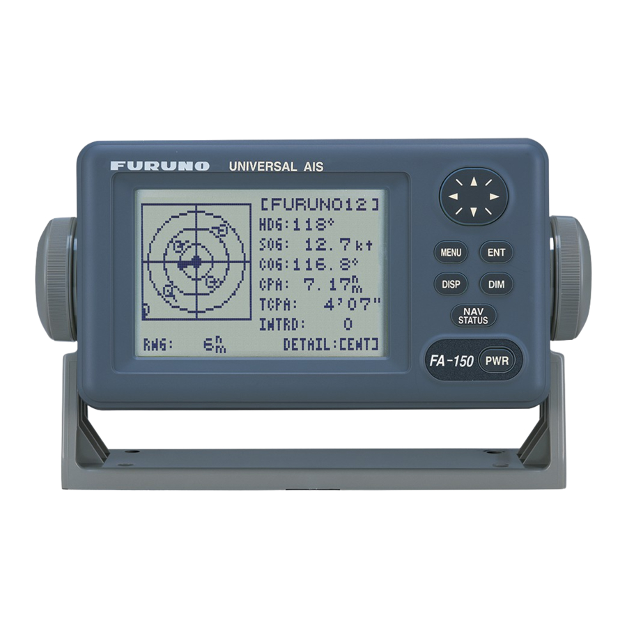
OPERATION Description of Controls UNIVERSAL AIS LCD Screen: Displays various data. CursorPad: Shifts cursor; chooses menu items and options; selects alphanumeric data. MENU key: Opens the menu. ENT key: Terminates keyboard input; changes screen. DISP key: Chooses a display screen; closes menu. DIM key: Adjusts panel dimmer and LCD contrast. -
Page 13: Turning The Power On And Off
1. OPERATION Turning the Power On and Off Press the PWR key to turn the equipment on or off. When powered, the equipment sounds a beep then proceeds in the sequence shown below. The startup screen displays the program version number and the results of the ROM, RAM and backup data test, showing OK or “NG”... - Page 14 The FA-150 should be powered while underway or at anchor. The master may switch off the AIS if he believes that the continual operation of the AIS might compromise the safety or security of his ship. The AIS should be restarted once the source of danger has gone.
-
Page 15: Adjusting Panel Dimmer And Contrast
1. OPERATION Adjusting Panel Dimmer and Contrast The panel dimmer and display contrast may be adjusted as follows: 1. Press the DIM key to show the dimmer and contrast setting screen. 2. Use ▲ or ▼ to adjust the panel dimmer; ◄ or ► to adjust the contrast. (The default dimmer and contrast settings are 4 and 45, respectively. -
Page 16: Menu Overview
Menu Overview You can select the functionality of the equipment through the menu. If you get lost in operation, press the MENU key until you return to the main menu. The complete menu tree is provided in the Appendix. 1.4.1 Menu operating procedure 1. -
Page 17: Settings Menu
1. OPERATION Selecting an option The example below shows how to select an option from the USER SETTINGS menu. a) A window showing the options for the item selected is overlaid on the sub-menu. For example, the options for KEY BEEP are as shown below. [USER SETTINGS] KEY BEEP ALARM BUZZER : ON... -
Page 18: Entering Voyage-Related Data
Entering Voyage-Related Data There are six items on the NAV STATUS menu that you will need to enter at the start of a voyage. • Navigation status • Destination 1. Press the NAV STATUS key to open the NAV STATUS menu. 2. - Page 19 1. OPERATION 4. NEW is selected; press the ENT key. NAV STATUS menu, DESTINATION sub-menu, destination input 5. Press the ENT key. Enter destination then press the ENT key. You can use up to 20 alphanumeric characters (\, ^, !, ,, $, and * count as three characters), and enter 20 destinations.
- Page 20 6. Press ► to show the ARRIVAL TIME sub-menu. [ARRIVAL TIME] DATE [UTC]: TIME[UTC]: 7. DATE[UTC] is selected; press the ENT key. 8. Enter the date of arrival then press the ENT key. 9. TIME[UTC] is selected; press the ENT key. 10.
- Page 21 1. OPERATION 10 FUTURE USE ALL SHIPS OF THIS TYPE 11 FUTURE USE CARRYING DG, HS, OR MP( ) 12 FUTURE USE CARRYING DG, HS, OR MP(Y) 13 FUTURE USE CARRYING DG, HS, OR MP(Z) 14 FUTURE USE CARRYING DG, HS, OR MP(OS) 15 FUTURE USE FUTURE USE 16 FUTURE USE FUTURE USE 17 FUTURE USE FUTURE USE...
-
Page 22: Setting Cpa/Tcpa
Setting CPA/TCPA Set the CPA (Closest Point of Approach) and TCPA (Time to Closest Point of Approach) range for which you want to be alerted to AIS targets which can be on a collision course. When a ship’s CPA and TCPA are lower than that set here, the buzzer sounds (if active) and the message COLLISION ALARM appears. -
Page 23: Selecting A Display
1. OPERATION Selecting a Display Use the DISP key to select a display. Each time the key is pressed, the display changes in the sequence shown below. TARGET LIST (See section 1.7.2. ) Switch between these displays with OWN STATIC OWN STATIC DATA 1 DATA 2... -
Page 24: Plotter Display
1. OPERATION 1.7.1 Plotter display The plotter display, which automatically appears after the power-on sequence, shows the name, heading, SOG, COG, CPA and TCPA of AIS-equipped ships, AIS-SARTs, etc. within the range selected. The number of dangerous targets is also indicated. Data for ship target A target marker (hollow triangle) indicates the presence of a vessel equipped with AIS in a certain location and course. - Page 25 1. OPERATION Operations on the plotter display 1. Press the DISP key to show the plotter display. 2. Use ▼ or ▲ to select the range. The available ranges are (in nm) 0.125, 0.25, 0.5, 0.75, 1.5, 3, 6, 12, and 24. 3.
-
Page 26: Target List (Displaying Target Data)1-15
1.7.2 Target list (displaying target data) 1. At the plotter display, press the DISP key to show the TARGET LIST, which lists all AIS targets and AIS-SARTs being detected by the FA-150. Note 1: The dangerous target list appears when there are dangerous targets. - Page 27 1. OPERATION Ship info display, mobile class A 1-16...
- Page 28 1. OPERATION Ship info display, mobile class B 1-17...
- Page 29 1. OPERATION Base station display SAR (Search and Rescue) info display 1-18...
- Page 30 1. OPERATION AIS-SART info display 1-19...
- Page 31 1. OPERATION AtoN (Aid to Navigation) info display 1-20...
- Page 32 The table below shows all the AtoN types and names that may appear on the AtoN INFO display. A to N type and name Type DEFAULT, TYPE OF A TO N NOT SPECIFIED REFERENCE POINT RACON OFF SHORE STRUCTURE SPARE LIGHT, WITHOUT SECTORS LIGHT, WITH SECTORS LEADING LIGHT FRONT...
-
Page 33: Dangerous (Target) List
1. OPERATION 1.7.3 Dangerous (target) list You can easily find dangerous ships whose CPA and TCPA are lower than the CPA and TCPA alarm settings. 1. At the plotter display, press the DISP key to show the Target List (see section 1.7.2). - Page 34 1. OPERATION 1-23...
-
Page 35: Dynamic Data Display
1. OPERATION 1.7.5 Dynamic data display The OWN DYNAMIC DATA display shows your ship’s dynamic data, which includes time, date, ship’s position, SOG, COG, heading, ROT, position accuracy, and RAIM use. The Officer of the Watch should periodically check position, SOG and sensor information for quality. -
Page 36: Messages
Messages You may send and receive messages via VHF channels , to a specified MMSI or all AIS-equipped ships in the area. Messages can be sent to warn of safety of navigation; for example, an iceberg sighted. Routine messages are also permitted. - Page 37 1. OPERATION 5. ADRS TYPE is selected; press the ENT key. 6. Select ADRS CAST to send a message to a specific AIS-equipped ship, or BROAD CAST to send a message to all AIS-equipped ships within broadcasting range. Press the ENT key. 7.
-
Page 38: Receiving Messages
19. Press ◄ to select YES then press the ENT key to send your message. Message status is shown as follows: AIS message status messages and their meanings Message NOW SENDING. SEND MESSAGE COMPLETE. PRESS ANY KEY SEND MESSAGE UNSUCCESSFUL. PRESS ANY KEY SEND MESSAGE UNSUCCESSFUL. - Page 39 1. OPERATION 5. To view the contents of a message, select the message then press the ENT key. Below is an example of a received message. 6. Press the DISP key to close the log. Automatically displaying incoming messages You can display incoming messages automatically as follows: 1.
-
Page 40: Tx And Rx Message Logs
1.8.3 TX and RX message logs The FA-150 stores the latest 20 each of transmitted and received messages in respective message logs. When a log becomes full, the oldest message in the log is automatically deleted to make room for the latest. When you receive a message, a popup shows MESSAGE! To display a message log, do the following: 1. -
Page 41: Regional Operating Channels
1. OPERATION Regional Operating Channels AIS operates primarily on two dedicated VHF channels, CH 2087 and CH2088. Where these channels are not available regionally, the AIS is capable of being automatically switched to designated alternate channels by means of a message from a shore facility. -
Page 42: Displaying, Editing Regional Operating Area Status
1.9.2 Displaying, editing regional operating area status You may display the status of regional operating areas currently memorized in the equipment. Nine of any combination of AIS message from shore-based AIS, DSC message, manual settings and commands from ECDIS or a PC may be registered and one will be HIGH SEA. - Page 43 1. OPERATION 5. Press the ENT key to show details. 6. POWER is selected; press the ENT key to show the channel power options. 7. Select power desired then press the ENT key. 8. CH NO. CH-A is selected; press the ENT key. 9.
- Page 44 20. LON of RIGHT TOP is selected; press the ENT key. Enter longitude for the right-top position (northeast point) of the AIS operating area then press the ENT key. 21. LAT of LEFT BOTTOM is selected; press the ENT key. Enter latitude for the left-bottom position (southwest point) of the AIS operating area then press the ENT key.
-
Page 45: Enabling/Disabling Alarm Buzzer, Key Beep
1. OPERATION 1.10 Enabling/Disabling Alarm Buzzer, Key Beep You may turn on or off the buzzers that sound for alarms or incoming messages. Further, you may turn off the beep, which sounds for valid key input. Note that the alarm buzzer is not related to a radar or ECDIS alarm. 1. -
Page 46: Long Range Mode
DISP SART TEST : ON LR MODE : AUTO RECEIVED MSG CPA/TCPA ALARM AUTO MANUAL [RECEIVED LR] MMSI: 431456789 NAME: FURUNO Press key RESPONSE? YES: [ENT] NO: OTHER 1. OPERATION [LR RESPONSE] MMSI: 431456789 NAME: FURUNO PRESS ANY KEY 1-35... - Page 47 Meaning Ship name, call sign, IMO number Date message created Position Course over ground Speed over ground Waypoint, ETA Draft Ship type, Load Ship length, width, type Number of crew 1-36 [LR RESPONSE] MMSI: 431456789 NAME: FURUNO PRESS ANY KEY...
-
Page 48: Viewing Initial Settings
[ENT] key. VIEW LAN PORT* VIEW PRIORITY VIEW QUALITY* Shown when optional LAN kit is installed. Shown with Inland AIS. 1. OPERATION : 999999999 : FURUNO QUIT [MENU] A: 45m B: 15m QUIT[MENU] A: 45m B: 15m QUIT[MENU] QUIT [MENU]... - Page 49 1. OPERATION This page intentionally left blank. 1-38...
-
Page 50: Inland Ais Operation
INLAND AIS OPERATION This section provides the operating procedures for the Inland AIS feature, which allows use of the AIS transponder on inland waterways or the open sea. Only those procedures that are different from the Class A AIS transponder are presented. -
Page 51: Inland Ais
2. INLAND AIS Selecting AIS Mode The Inland AIS has two operating modes: Inland (inland waterways) and SOLAS (SOLAS compliant class A AIS transponder). Select desired mode as follows: 1. Press the NAV STATUS key to open the NAV STATUS menu. 2. -
Page 52: Entering Voyage-Related Data
Entering Voyage-Related Data Before you embark on a voyage using Inland AIS, set the various voyage related data (see the list below) on the NAV STATUS menu. • Destination • Arrival time • Draught • Cargo type • ERI code 1. - Page 53 2. INLAND AIS 4. Press the ENT key. Enter destination then press the ENT key. You can use up to 20 alphanumeric characters, and enter 20 destinations. (For how to enter alphanumeric characters, see “Entering alphanumeric data” on page 1-6.) Note 1: Each of the characters shown below counts as three characters.
- Page 54 17. Select type of vessel/cargo, referring to the table on page 1-10, then press the ENT key. Note 1: Only the second digit for the type of vessel is entered here; the first digit is entered on the initial settings menu, during installation. Note 2: When “Tanker”...
- Page 55 2. INLAND AIS 29. Enter the total number of persons (sum of crew, passengers and shipboard personnel) onboard then press the ENT key. Note: NO. OF PERSONS is sent in IFM16 messages. 30. Press ► to go to the LENGTH&BEAM sub-menu. 31.
- Page 56 35. HAZARDOUS CARGO is selected; press the ENT key. NUMBER OF CONES 0 NUMBER OF CONES 1 NUMBER OF CONES 2 NUMBER OF CONES 3 B-FLAG UNKNOWN 36. If your ship is carrying hazardous cargo, "cones" (max. 3) have to be shown on the mast, in daylight with cones and nighttime with blue lights.
-
Page 57: Static Data
“OWN STATIC DATA”. Use ▼ or ► to go forward, ▲ or ◄ to go back. [STATIC DATA] MMSI : 123456789 NAME : FURUNO VOYAGER CALL SIGN: ZL6DEF1 IMO NO. : 9241062* : 1654321 AIS MODE : SOLAS... - Page 58 2. INLAND AIS...
-
Page 59: Dynamic Data
2. INLAND AIS Dynamic Data The DYNAMIC DATA display shows your ship’s dynamic data, which includes date, time, ship’s position, etc. To show these displays, press the DISP key three times at the plotter display. The Officer of the Watch should periodically check position, speed over ground and sensor information for quality. -
Page 60: Details Ship Display (Mobile Class A)
Details Ship Display (Mobile Class A) See section 1.7.2 for how to show this display. [SHIP INFO] MMSI [A] : 431099806 NAME : FURUNO* CALL SIGN : ZL6DEF1* IMO NO. : 9241062 : 1654321* BLUE SIGN: YES [SHIP INFO] LAT : 51 ° 55.0213'N 4 °... - Page 61 2. INLAND AIS (Continued from previous page) [SHIP INFO] TYPE OF SHIP: ***TYPE DETAIL*** FUTURE USE CARGO SHIP CARRYING DG, HS, OR MP(X) [SHIP INFO] ERI CODE: **CODE DETAIL*** MOTOR FREIGHTER WITH TANKER [SHIP INFO] SENSOR QUALITY SPEED: COURSE: HEADING: DESTINATION ROTTERDAM ETA: 15/JUL 17:21 UTC...
-
Page 62: Inland Ais Specific Messaging
Inland AIS Specific Messaging 2.7.1 Text message 1. Press the MENU key to open the menu. 2. Select MSG then press the ENT key. 3. TEXT is selected; press the ENT key. 4. CREATE MSG is selected; press the ENT key. 5. - Page 63 2. INLAND AIS 7. Select ADRS CAST to send a message to a specific AIS-equipped ship, or BROAD CAST to send a message to all AIS-equipped ships within broadcasting range of your ship. Press the ENT key. For ADRS CAST, select MMSI then enter MMSI no.
-
Page 64: Eta And Rta Messages
Message status is shown as follows: AIS message status messages and their meanings Message NOW SENDING. SEND MESSAGE COMPLETE. PRESS ANY KEY. SEND MESSAGE UNSUCCESSFUL. PRESS ANY KEY SEND MESSAGE UNSUCCESSFUL. MMSI: XXXXXXXXX PRESS ANY KEY. NOW WAITING RESPONSE. PRESS ANY KEY. 2.7.2 ETA and RTA messages The purpose of an ETA message is to apply for a time slot at a lock, bridge or... - Page 65 2. INLAND AIS 3. Select ETA/RTA then press the ENT key. 4. CREATE MSG is selected; press the ENT key. 5. SET MSG TYPE is selected; press the ENT key. 6. MMSI is selected; press the ENT key. 7. Enter the MMSI of the lock/bridge/terminal you want to pass through then press the ENT key.
- Page 66 13. Select SET DESTINATION then press the ENT key. [SET DESTINATION] * * * * * * * * * * * * * (0/0) [NEW?] (If you have entered some destinations, they appear here.) 14. NEW is selected. If your destination is shown on screen, select it, press the ENT key then go to step 18.
- Page 67 2. INLAND AIS 19. Select SET ETA then press the ENT key. 20. DATE[UTC] is selected; press the ENT key. 21. Enter the day (1-2 digits) and month (three-character abbreviation) of ETA then press the ENT key. 22. TIME[UTC] is selected; press the ENT key. 23.
-
Page 68: No. Of Persons Message
5. Select the message then press the ENT key. Lock Status - Operational - Limited Operation* - Out of Order [RTA LOG] - Not Available STATUS Date and time RTA: 05/JUN lock authority requests your ship to arrive to the lock * Obstructed by technical conditions, only one lock RTA message (page 1) - Page 69 2. INLAND AIS 5. SET MSG TYPE is selected; press the ENT key. 6. ADRS TYPE is selected; press the ENT key. 7. Select ADRS CAST to send a message to a specific AIS-equipped ship or authority, or BROAD CAST to send a message to all AIS-equipped ships within broadcasting range.
-
Page 70: Emma Warning Message
14. Press the MENU key to return to the CREATE MSG menu. Note: To view your message before sending it, return to the CREATE MSG screen, select VIEW MSG then press the ENT key. 15. Select SEND MSG then press the ENT key. You are asked if you are sure to send the message. -
Page 71: Wind Direction
2. INLAND AIS [EMMA WARNING] START TIME [UTC] 12/JUN 11:30 END TIME [UTC] 12/JUN 11:35 Start and end times of validity of warning Item Description TYPE FI: Fire in the Forests FO: Fog FL: Flood HT: High Temperature LT: Low Temperature RA: Rain SN: Snow and Ice TH: Thunderstorm... -
Page 72: Water Level Message
2.7.5 Water level message The water level message is sent by base stations to inform skippers about actual water levels in their area. It is additional short-term information to the water levels distributed via Notices to Skippers. The message contains the country code(location), gauge ID and water level. -
Page 73: Message Logs
2. INLAND AIS 2.7.6 Message logs TX logs The TX logs store transmitted text messages, ETA, and no. of persons messages, in respective logs. To see a TX message, do the following: 1. Press the MENU key to open the menu. 2. - Page 74 RX logs The RX logs store received text messages, RTA, EMMA warning and water level messages, in respective logs. When you receive one of those messages, a popup shows "MESSAGE! XXX (XXX=message type)". To see the contents of the message, do the following: 1.
-
Page 75: Viewing Initial Settings
LAN kit is installed. 2-26 [VIEW MMSI] [VIEW INT ANT POSN] MMSI : 999999999 NAME : FURUNO CALL SIGN: FQC3544 IMO NO. : 009999999 ENI: 01820013 QUIT [MENU] [VIEW EXT ANT POSN] [VIEW SHIP TYPE] TYPE NO : 0... -
Page 76: Maintenance, Troubleshooting
MAINTENANCE, TROUBLESHOOTING WARNING ELECTRICAL SHOCK HAZARD Do not open the equipment. Only qualified personnel should work inside the equipment. Maintenance Regular maintenance is necessary to maintain performance. A monthly maintenance program should be established and should at least include the items listed in the table below. -
Page 77: Replacement Of Fuse, Resetting The Breaker
3. MAINTENANCE, TROUBLESHOOTING Replacement of Fuse, Resetting the Breaker 3.2.1 Replacement of fuse The power cable for the monitor unit contains a 3A fuse which protects the equipment from overvoltage, reverse polarity and equipment fault. If the power cannot be turned on, check if the fuse has blown. If the fuse has blown, find the cause before replacing the fuse. -
Page 78: Troubleshooting
Troubleshooting The troubleshooting table below provides common symptoms of trouble and the means to rectify them. If you cannot restore normal operation, do not attempt to check inside the equipment. Refer any repair work to a qualified technician. Symptom Power Cannot turn on the power. - Page 79 3. MAINTENANCE, TROUBLESHOOTING 3. MONITOR TEST is selected; press the ENT key. The test program automatically proceeds in the sequence shown below. XX.XX = Program version no. [MONITOR TEST] BOOT NO.: 2450020-XX.XX PROG NO.: 2450021-XX.XX SDRAM: PORT : QUIT[MENU] 3 TIMES a) The first screen in the test shows boot no.
-
Page 80: Transponder Test
3.4.2 Transponder test The transponder test consists of two tests: memory test and internal GPS receiver test. Memory test The memory can be checked for proper operation and the program number displayed as follows: 1. Press the MENU key to open the main menu. 2. - Page 81 3. MAINTENANCE, TROUBLESHOOTING Internal GPS test The internal GPS receiver can be checked for proper operation as follows: 1. Press the MENU key to open the main menu. 2. Select DIAGNOSTICS then press the ENT key. 3. Select TRANSPONDER TEST then press the ENT key. 4.
-
Page 82: Power On/Off History
3.4.3 Power on/off history The PWR ON/OFF HISTORY log shows the date and time of the latest 30 power-ons and power-offs. If the interval between power-off and power-on is less than 15 minutes those times are not shown. 1. Press the MENU key to open the main menu. 2. -
Page 83: Alarm Status
3. MAINTENANCE, TROUBLESHOOTING Alarm Status The alarm sounds for equipment error and is accompanied by a flashing popup indication. Press any key to silence the alarm and erase the popup. To see which alarm(s) has been violated, display the ALARM STATUS log as shown below. -
Page 84: Error And System Messages
Error and System Messages The FA-150 displays the following error and system messages to alert you to errors and events. Error and system messages and their meanings Message CAN’T DISPLAY INVALID DATA CAN’T DISPLAY OVER LAT85° COLLISION ALARM COMMUNICATION ERROR DIFFERENT FROM ANT POS VALUE ERROR REGIST... - Page 85 3. MAINTENANCE, TROUBLESHOOTING OUT OF RANGE! 0-65535 OUT OF RANGE! 10-30 OUT OF RANGE! BEAM:0-100 OUT OF RANGE! CH-A(CH-B) DOESN'T EXIST OUT OF RANGE! CPA:0-6.00 OUT OF RANGE! CREW:0-254 OUT OF RANGE! DAY OUT OF RANGE! DRAUGHT:0-20.0 OUT OF RANGE! DRAUGHT:0-25.5 OUT OF RANGE! HOUR:0-23* OUT OF RANGE!: INVALID CHANNEL...
-
Page 86: Gps Monitor
GPS Monitor The GPS monitor display shows information about the built-in GPS receiver, including position, speed over ground, course over ground, date, time, mode position accuracy, position-fixing status and RAIM status. 1. Press the MENU key to open the menu. 2. -
Page 87: Displaying Sensor Status
3. MAINTENANCE, TROUBLESHOOTING Displaying Sensor Status The SENSOR STATUS screen shows sensor status. 1. Press the MENU key. 2. Select SENSOR STATUS then press the ENT key. Sensor status message 3. Press the DISP key to close the display. Sensor status messages and their meanings Sensor Status Message CH MANAGEMENT EXT DGNSS... -
Page 88: Restoring Default Settings
Restoring Default Settings You may clear all or specific settings to start afresh with default settings. When all data is cleared, the default settings for all items in the INIT SETTING and SYSTEM SETTINGS sub-menus are restored. GPS data is also cleared; however, MMSI and IMO numbers, ship’s name and call sign are not cleared. -
Page 89: Ais-Sart Test Indication In Target List
3. MAINTENANCE, TROUBLESHOOTING 3.10 AIS-SART Test Indication in Target List The FA-150 can confirm if an AIS-SART is working properly. This test requires message 1 data (MMSI No. 97 XXXXXXX, NAV STATUS: 15). Note that this setting is turned off when the power is turned off. 1. -
Page 90: Appendix
APPENDIX Menu Tree - Class A AIS AP-1... - Page 91 APPENDIX (Continued from previous page) CHANNEL VIEW CHANNEL (View power and channel settings of channel in use.) SETTINGS EDIT CHANNEL DIAG- MONITOR TEST (Displays PROG NO. and BOOT NO.; checks ROM, RAM, LCD, controls.) NOSTICS TRANSPONDER TEST PWR ON/OFF HISTORY (Log for time of equipment power on and off.) TX ON/OFF HISTORY (Log for time of equipment transmission on and off.) MEMORY CLEAR ACTIVATE KEY (DEVICE ID, KEY[ACTIVATED])
-
Page 92: Menu Tree - Inland Ais
Menu Tree - Inland AIS [MENU] key TEXT CREATE MSG ETA/RTA TX LOG NO. OF PERSONS RX LOG EMMA WARNING CREATE MSG WATER LEVEL ETA LOG RTA LOG CREATE MSG TX LOG SENSOR STATUS (Display sensor status.) INTERNAL GPS (Displays data about internal GPS receiver.) USER SETTINGS KEY BEEP (ON, OFF) ALARM BUZZER (ON, OFF) - Page 93 APPENDIX (Continued from previous page) CHANNEL VIEW CHANNEL (View power and channel settings of channel in use.) SETTINGS EDIT CHANNEL DIAG- MONITOR TEST (Displays program no.; checks ROM, RAM, LCD, controls.) NOSTICS MEMORY TEST (Displays PROG NO.; TRANSPONDER checks ROM, RAM, and MOT HW.) TEST GPS TEST (Display PROGRAM NO.
-
Page 94: Parts List
This equipment contains complex modules in which fault diagnosis and repair down to component level are not practical (IMO A.694(17)/8.3.1). Only some discrete components are used. FURUNO Electric Co., Ltd. believes identifying these components is of no value for shipboard maintenance; therefore, they are not listed in the manual. Major modules can be located on the parts location photo on page AP-6 and AP-7. -
Page 95: Parts Location
APPENDIX Parts Location Monitor unit CPU Board 24P0062 Transponder unit TX Board 24P0032 PWR Board 24P0037 Transponder unit, top cover removed AP-6 Monitor unit, rear cover opened MOT Board 24P0036... - Page 96 RX2 Board 24P0033 RX1 Board 24P0033 DSC Board 24P0033 Transponder unit, bottom cover removed APPENDIX GPS Receiver GN-8093 MAIN Board GPSTB Board 24P0035 24P0043 AP-7...
-
Page 97: Digital Interface (Iec 61162-1 Edition 2, Iec 61162-2
APPENDIX Digital Interface (IEC 61162-1 Edition 2, IEC 61162-2) Sentence data Input sentences ABM, ACA, ACK, AIR, BBM, DTM, GBS, GGA, GLL, GNS, HDT, LRF, LRI, OSD, PIWWIVD, PIWWSPW, PIWWSSD, PIWWVSD, RMC, ROT, SSD, VBW, VSD, VTG Output sentences ABK, ACA, ACS, ALR, LRF, LR1, LR2, LR3, TXT, PIWWSPR, VDM, VDO Transmission interval ABK: With each event ACA, ACS: At RX... -
Page 98: Serial Interface I/O Circuit
Serial interface I/O circuit COM1, 2, 3 port Baud rate selectable from 4800 and 38400 (bps). LTC1535C COM 4, 5 port Baud rate selectable from 4800 and 38400 (bps). LTC1535C RD_2 2.2kΩ RD_1 COM6 port Baud rate selectable from 4800 and 38400 (bps). 2_ RD 2.2k 1_ RD/A D_ DATA... -
Page 99: Sentence Description
APPENDIX DISP port Baud rate selectable from 4800 and 38400 (bps). LTC1535C Blue Sign port TLP181 270 ohm Sentence description Input sentences ABM - Addressed binary and safety related message !--ABM,x,x,x,xxxxxxxxx,x,x.x,s--s,x*hh<CR><LF> | | | | | | | | | | | | +-------- 7 | | |... - Page 100 ACA - AIS regional channel assignment message $--ACA,x,IIII.I, a,yyyyy.y,a,IIII.I,a,yyyyy.y,a,x,xxxx,x,xxxx,x,x,x,a,x,hhmmss.s*hh<CR><LF> 1. Sequence number, 0 to 9 2. Region Northeast corner latitude - N/S 3. Region Northeast corner longitude - E/W 4. Region Southwest corner latitude - N/S 5. Region Southwest corner longitude - E/W 6.
- Page 101 APPENDIX AIR - AIS interrogation request $--AIR,xxxxxxxxx,x.x,x,x.x,x,xxxxxxxxx,x.x,x*hh<CR><LF> +--------------- 6 | | +--------------------- 5 | +------------------------ 4 +--------------------------- 3 +------------------------------ 2 +------------------------------------- 1 1. MMSI of interrogated station 1 2. ITU-R M.1371 message requested from station 1 3. Message sub-section 4. Number of second message requested from station 1 5.
- Page 102 DTM - Datum reference $--DTM,ccc,a,x.x,a,x.x,a,x.x,ccc*hh<CR><LF> +------ 6 | +---------- 5 | +---+------------- 4 | +---+------------------- 3 | +------------------------- 2 +---------------------------- 1 1. Local datum W84 - WGS84 W72 - WGS72 S85 - SGS85 P90 - PE90 999 - User defined IHO datum code 2.
- Page 103 APPENDIX GGA - Global positioning system (GPS) fix data $--GGA,hhmmss.ss,llll.ll,a,yyyyy.yy,a,x,xx,x.x,x.x,M,x.x,M,x.x,xxxx*hh<CR><LF> +----+--------------------------------- 3 +---+--------------------------------------------- 2 +------------------------------------------------------------- 1 1. Not used 2. Latitude, N/S 3. Longitude, E/W 4. GPS quality indicator 5. Not used 6. Not used 7. Not used 8. Not used 9.
- Page 104 GNS - GNSS fixed data $--GNS,hhmmss.ss,llll.ll,a,yyyyy.yy,a,c--c,xx,x.x,x.x,x.x,x.x,x.x*hh<CR><LF> +-------+--------------------------------- 3 +--+--------------------------------------------- 2 +------------------------------------------------------------- 1 1. Not used 2. Latitude, N/S 3. Longitude, E/W 4. Mode indicator 5. Not used 6. Not used 7. Not used 8. Not used 9. Not used 10. Not used 11.
- Page 105 APPENDIX LRI - Long-range interrogation $--LRI,x,a,xxxxxxxxx,xxxxxxxxx,llll.ll,a,yyyyy.yy,a,llll.ll,a,yyyyy.yy,a*hh<CR><LF> +--+------------------------------------- 5 +--------------------------------------------------- 4 +------------------------------------------------------------- 3 | +------------------------------------------------------------------- 2 +--------------------------------------------------------------------- 1 1. Sequence number, 0 to 9 2. Control Flag 3. MMSI of requestor 4. MMSI of destination 5. Latitude - N/S(north-east coordinate) 6. Longitude - E/W(north-east coordinate) 7.
- Page 106 RMC - Recommended minimum specific GPS/TRANSIT data $--RMC,hhmmss.ss,A,llll.ll,a,yyyyy.yy,a,x.x,x.x,xxxxxx,x.x,a,a*hh<CR><LF> +---+---------------------------------------- 3 +--------------------------------------------------- 2 +---------------------------------------------------------- 1 1. UTC of position fix 2. Status: A=data valid, V=navigation receiver warning 3. Latitude, N/S 4. Longitude, E/W 5. Speed over ground, knots 6. Course over ground, degrees true 7.
- Page 107 APPENDIX SSD - UAIS ship static data $--SSD,c--c,c--c,xxx,xxx,xx,xx,c, aa*hh<CR><LF> | | | | | | | | +--- 8 | +----- 7 +------- 6 +---------- 5 +-------------- 4 +------------------ 3 +---------------------- 2 +--------------------------- 1 1. Ship's Call Sign, 1 to 7 characters 2.
- Page 108 VSD - UAIS voyage static data $--VSD,x.x,x.x,x.x,c--c,hhmmss.ss,xx,xx,x.x,x.x*hh<CR><LF> +----------------------- 5 +------------------------------ 4 +----------------------------------- 3 +--------------------------------------- 2 +------------------------------------------- 1 1. Type of ship and cargo category, 0 to 255 2. Maximum present static draught (Solas Draught), 0 to 25.5 Meters 3. Persons on-board, 0 to 8191 4.
- Page 109 APPENDIX Output sentences ABK - UAIS addressed and binary broadcast acknowledgement $--ABK,xxxxxxxxx,a,x.x,x,x*hh<CR><LF> | | | | | | | +--- 6 | | +----- 5 | +------- 4 | +---------- 3 +------------- 2 +------------------- 1 1. MMSI of the addressed AIS unit 2.
- Page 110 LRF - See “Input sentences.” LR1 - Long-range reply with destination for function request “A” $--LR1,x,xxxxxxxxx,xxxxxxxxx,c--c,c--c,xxxxxxxxx*hh<CR><LF> +---------------------- 4 +------------------------------ 3 +---------------------------------------- 2 +---------------------------------------------- 1 1. Sequence Number 2. MMSI of responder 3. MMSI of requestor(reply destination) 4. Ship’s name, 1 to 20 characters 5.
- Page 111 APPENDIX LR3 - Long-range reply for function requests “I, O, P, U and W” $--LR3,x,xxxxxxxxx,c--c,xxxxxx,hhmmss.ss,x.x,x.x,x.x,x.x,x.x,x.x*hh<CR><LF> +---------------------------------------- 4 +---------------------------------------------- 3 +------------------------------------------------------ 2 +------------------------------------------------------------ 1 1. Sequence Number 2. MMSI of responder 3. Voyage destination, 1 to 20 characters 4. ETA Date: ddmmyy 5.
- Page 112 VDM - VHF data-link message !--VDM,x,x,x,a,s--s,x*hh<CR><LF> | | | | | | | | | +--- 7 | | | | | +----- 6 | | | | +-------- 5 | | | +------------ 4 | | +-------------- 3 | +---------------- 2 +------------------ 1 1.
-
Page 113: Inland Ais Specific Sentences
APPENDIX Inland AIS specific sentences Input sentences PIWWIVD - Inland waterway voyage data $PIWWIVD x, x, x, xx.xx, xx.xx, x , xxx, xxxx, xxx, hh<CR><LF> 1. Reporting rate, 0-15 1 to 9 2. No. of blue cones, 0-3, 4=B-Flag, 5=unknown (default) 3. - Page 114 PIWWSSD - Inland waterway static ship data $PIWWSSD CCCCCCCC, xxxx, xxxx, xxxx, x, x, x, hh<CR><LF> 1. ENI no. (00000000-9999 9999) 2. ERI ship type (0-9999) 3. Length of ship (0.0-800.0(m)) 4. Beam of ship (0.0-100.0(m)) 5. Quality of speed information (1: High, 0: Low) 6.
- Page 115 APPENDIX Output sentences PIWWSPR - Inland AIS security password response $PIWWSPR a, x, x, x, hh<CR><LF> 1. Mode (E: Password input, C: Password change) 2. Password level (1: Maintenance password, 2: User password 3. Valid time (0-60 (s)) 4. Status (0: Pass, 1: Fail) AP-26...
-
Page 116: Vhf Channel List
VHF Channel List International mode Ch No. Freq. Ch No. 1001 156.05 1088 1002 156.1 1201 1003 156.15 1202 1004 156.2 1203 1005 156.25 1204 156.3 1205 1007 156.35 1206 1018 156.9 1207 1019 156.95 1020 1021 157.05 1022 157.1 1023 157.15 1024... -
Page 117: Usa Mode
APPENDIX USA mode Ch No. Freq. Ch No. 1001 156.05 1088 1201 1003 156.15 1202 1203 1005 156.25 1204 156.3 1205 1007 156.35 1206 1018 156.9 1207 1019 156.95 1020 1021 157.05 1022 157.1 1023 157.15 1024 157.2 1025 157.25 1026 157.3 1027... -
Page 118: Eri Codes
ERI Codes Full code 8000 No VESSEL., TYPE UNKNOWN 8010 MOTOR FREIGHTER 8020 MOTOR TANKER 8021 MOTOR TANKER, LIQUID CARGO, TYPE N 8022 MOTOR TANKER, LIQUID CARGO, TYPE C 8023 MOTOR TANKER, DRY CARGO AS IF LIQUID (E.G.CEMENT) 8030 CONTAINER VESSEL 8040 GAS TANKER 8050... -
Page 119: Terminology, Units, Symbols
APPENDIX Terminology, Units, Symbols Terminology Abbreviation Two Dimensional Positioning Three Dimensional Positioning Addressed Binary Message ADRS Address Automatic Identification System ALARM Alarm Altitude Antenna April AtoN Aids To Navigation August AUTO Automatic AVAIL Available Bearing Channel Change Clear CNCL Cancel Course Over the Ground CONT Contrast... - Page 120 Electronic Reporting International Error Estimated Time of Arrival External February FULL Full Ground GNSS Global Navigation Satellite System Global Positioning System High Heading HECT Hectometer High Harmful Substances (applies to AIS) Hardware Input/Output Identification Interface International Function Message International Maritime Organization INFO Information Internal...
- Page 121 APPENDIX Presentation Interface, Position Indicator PORT Port POSN Position Power Right Range / Bearing RAIM Receiver Autonomous Integrity Monitoring RAIN Rain Random Access Memory Reference Regional Function Message Range Read Only Memory Rate Of Turn Requested Time of Arrival Receive South SOG/COG Search And Rescue...
- Page 122 Units Abbreviation Unit ° degree(s) centimeter kilometer knot(s) meter minute(s) Nautical Mile(s) second(s) Symbols Icons APPENDIX AP-33...
- Page 123 APPENDIX This page intentionally left blank. AP-34...
-
Page 124: Specifications
SPECIFICATIONS OF U-AIS TRANSPONDER TRANSPONDER UNIT TX/RX frequency Output power Impedance DSC receiver Bandwidth MONITOR UNIT Display Display size GPS RECEIVER Receiving frequency Tracking code Number of channel Position fixing method Accuracy DGPS Tracking velocity Position-fixing time Position update interval 1 second typical DGPS data receiving INTERFACE Navigation I/O... -
Page 125: Power Supply
POWER SUPPLY Transponder unit Monitor unit AC/DC power supply unit (PR-240, option) ENVIRONMENTAL CONDITION Ambient temperature GPS/VHF antenna Other units Relative humidity Degree of protection GPS/VHF antenna Transponder unit Monitor unit Vibration COATING COLOR GPS antenna Transponder unit Monitor unit 12-24 VDC: 7-3.5 A 12-24 VDC: 0.3-0.15 A 100-115/200-230 VAC, 1 phase, 50/60 Hz... -
Page 126: Index
INDEX AIS-SART test indication ... 3-14 Alarm status... 3-8 Alarm status display ... 1-24 Breaker reset ... 3-2 Buzzer... 1-34 Channels setting ... 1-31 viewing... 1-30 Contrast ... 1-4 Controls ... 1-1 CPA/TCPA ... 1-11 Dangerous (target) list ... 1-22 Default settings... - Page 127 INDEX Parts location ... AP-6 Plotter display ...1-13 Power on/off...1-2 Power on/off history ...3-7 Program number record...vii PWR key...1-2 RTA message (Inland AIS)...2-18 RX logs class A ...1-29 inland AIS ...2-25 Sensor status...3-12 Static data class A AIS...1-22 Inland AIS ...2-8 System configuration ...
Need help?
Do you have a question about the UAIS TRANPONDER FA-150 and is the answer not in the manual?
Questions and answers