Furuno FA-150 Operator's Manual
U-ais transponder
Hide thumbs
Also See for FA-150:
- Installation manual (216 pages) ,
- Operator's manual (128 pages) ,
- Isntallation manual (57 pages)
Table of Contents
Advertisement
Quick Links
Advertisement
Table of Contents
Troubleshooting

Related Manuals for Furuno FA-150


Summary of Contents for Furuno FA-150
- Page 2 How to discard a used battery Some FURUNO products have a battery(ies). To see if your product has a battery, see the chapter on Maintenance. Follow the instructions below if a battery is used. Tape the + and - terminals of battery before disposal to prevent fire, heat generation caused by short circuit.
-
Page 3: Safety Instructions
Contact a power supply. Do not remove the label. FURUNO agent for service. If the label is missing or damaged, contact a FURUNO agent or dealer about Do not disassemble or modify the replacement. equipment. -
Page 4: Table Of Contents
TABLE OF CONTENTS 2.7.4 EMMA warning message..2-20 FOREWORD...........iv 2.7.5 Water level message ....2-22 2.7.6 Message logs ......2-22 SYSTEM CONFIGURATION ....vi Viewing Initial Settings......2-24 Selecting Menu Language ...... 2-25 PROGRAM NUMBER ......vii 2.10 Selecting Units of Measurement..... 2-26 SYSTEM OVERVIEW ......viii 2.11 Setting for Time Difference ..... -
Page 5: Foreword
M.1371-4 and DSC ITU-R M.825. It also complies with IEC 61993-2 (Type testing standard), IEC 60945 (EMC and environmental conditions). The FA-150 consists of VHF and GPS antennas, a transponder unit, a monitor unit, and several associated units. The transponder contains a VHF transmitter, two TDMA receivers on two parallel VHF channels, a DSC channel 70 receiver, interface, communication processor, and internal GPS receiver. - Page 6 The main features are • Safety of navigation by automatically exchanging navigational data between ships and between ship and coast • Static data: - MMSI (Maritime Mobile Service Identity) - IMO number (where available) - Call sign & name - Length and beam - Type of ship - Location of position-fixing antenna on the ship •...
-
Page 7: System Configuration
GVA-100 MONITOR UNIT FA-1502 Distributor unit (two units may DB-1 be connected) UNIVERSAL AIS MENU DISP STATUS FA-150 12-24 VDC TRANSPONDER UNIT FA-1501 External display, Pilot plug, NavNet2, Sensor Alarm system PC, Beacon receiver Blue Sign : Standard Power supply... -
Page 8: Program Number
PROGRAM NUMBER Location Program No. Version No. Date of Modification Monitor Unit 2450021 (Prog) 01.** (24P0062) 2450020 (Boot) 01.** September 2009 02.** 02.** May 2012 2450021 (Prog) 03.** MAIN Transponder Unit 2450018 01.** (24P0035) GPS Receiver 485026 40** Transponder Unit 02.** September 2009 03.**... -
Page 9: System Overview
SYSTEM OVERVIEW System overview The Automatic Identification System (AIS) was originally developed to aid the Vessel Traffic Services (VTS) by use of a VHF transponder working on Digital Selective Call (DSC) at VHF CH70, and is still in use along the UK coastal areas and others. Some time later the IMO developed a Universal AIS using the new sophisticated technology called Self-Organized Time Division Multiple Access (SOTDMA) based on a VHF Data Link (VDL). - Page 10 Not all ships carry AIS The Officer of the Watch (OOW) should always be aware that other ships, and in particular leisure craft, fishing boats and warships, and some coastal shore stations (including Vessel Traffic Service centers) might not be fitted with AIS. The OOW should also be aware that AIS fitted on other ships as a mandatory carriage requirement might be switched off by the master if its use might compromise the security of the vessel.
-
Page 11: Operation
OPERATION Description of Controls UNIVERSAL AIS MENU DISP STATUS FA-150 LCD Screen: Displays various data. CursorPad: Shifts cursor; chooses menu items and options; selects alphanumeric data. MENU key: Opens the menu. ENT key: Terminates keyboard input; changes screen. DISP key: Chooses a display screen;... -
Page 12: Turning The Power On And Off
1. OPERATION Turning the Power On and Off Press the PWR key to turn the equipment on or off. When powered, the equipment sounds a beep then proceeds in the sequence shown below. The startup screen displays the program version number and the results of the ROM, RAM and backup data test, showing OK or “NG”... - Page 13 1. OPERATION The FA-150 should be powered while underway or at anchor. The master may switch off the AIS if he believes that the continual operation of the AIS might compromise the safety or security of his ship. The AIS should be restarted once the source of danger has gone.
-
Page 14: Adjusting Panel Dimmer And Contrast
1. OPERATION Adjusting Panel Dimmer and Contrast The panel dimmer and display contrast may be adjusted as follows: 1. Press the DIM key to show the dimmer and contrast setting screen. D I M M E R ( 0 ~8 ) C O N T R A S T ( 0 ~6 3 ) EXIT: [ENT] 2. -
Page 15: Menu Overview
1. OPERATION Menu Overview You can select the functionality of the equipment through the menu. If you get lost in operation, press the MENU key until you return to the main menu. The complete menu tree is provided in the Appendix. 1.4.1 Menu operating procedure 1. - Page 16 1. OPERATION Selecting an option The example below shows how to select an option from the USER SETTINGS menu. a) A window showing the options for the item selected is overlaid on the sub-menu. For example, the options for KEY BEEP are as shown below. [USER SETTINGS] KEY BEEP ALARM BUZZER : ON...
-
Page 17: Entering Voyage-Related Data
1. OPERATION Entering Voyage-Related Data There are six items on the NAV STATUS menu that you will need to enter at the start of a voyage. • Navigation status • Cargo type • Arrival time • Destination • No. of persons •... - Page 18 1. OPERATION 4. NEW is selected; press the ENT key. [DESTINATION] ENTER A NEW DESTINATION QUIT:[NAV STATUS] NAV STATUS menu, DESTINATION sub-menu, destination input 5. Press the ENT key. Enter destination then press the ENT key. You can use up to 20 alphanumeric characters (\, ^, !, ,, $, and * count as three characters), and enter 20 destinations.
- Page 19 1. OPERATION 6. Press ► to show the ARRIVAL TIME sub-menu. [ARRIVAL TIME] DATE [UTC]: 25/APR TIME[UTC]: 0:00 7. DATE[UTC] is selected; press the ENT key. 8. Enter the date of arrival then press the ENT key. 9. TIME[UTC] is selected; press the ENT key. 10.
- Page 20 1. OPERATION 10 FUTURE USE ALL SHIPS OF THIS TYPE 60 PASSENGER SHIPS ALL SHIPS OF THIS TYPE 11 FUTURE USE CARRYING DG, HS, OR MP( ) 61 PASSENGER SHIPS CARRYING DG, HS, OR MP(X) 12 FUTURE USE CARRYING DG, HS, OR MP(Y) 62 PASSENGER SHIPS CARRYING DG, HS, OR MP(Y) 13 FUTURE USE CARRYING DG, HS, OR MP(Z) 63 PASSENGER SHIPS CARRYING DG, HS, OR MP(Z)
-
Page 21: Setting Cpa/Tcpa
1. OPERATION Setting CPA/TCPA Set the CPA (Closest Point of Approach) and TCPA (Time to Closest Point of Approach) range for which you want to be alerted to AIS targets which can be on a collision course. When a ship’s CPA and TCPA are lower than that set here, the buzzer sounds (if active) and the message COLLISION ALARM appears. -
Page 22: Selecting A Display
1. OPERATION Selecting a Display Use the DISP key to select a display. Each time the key is pressed, the display changes in the sequence shown below. PLOTTER DISPLAY PLOTTER (See section 1.7.1.) DISPLAY TARGET LIST DANGEROUS (TARGET) LIST DANGEROUS (See section 1.7.2. -
Page 23: Plotter Display
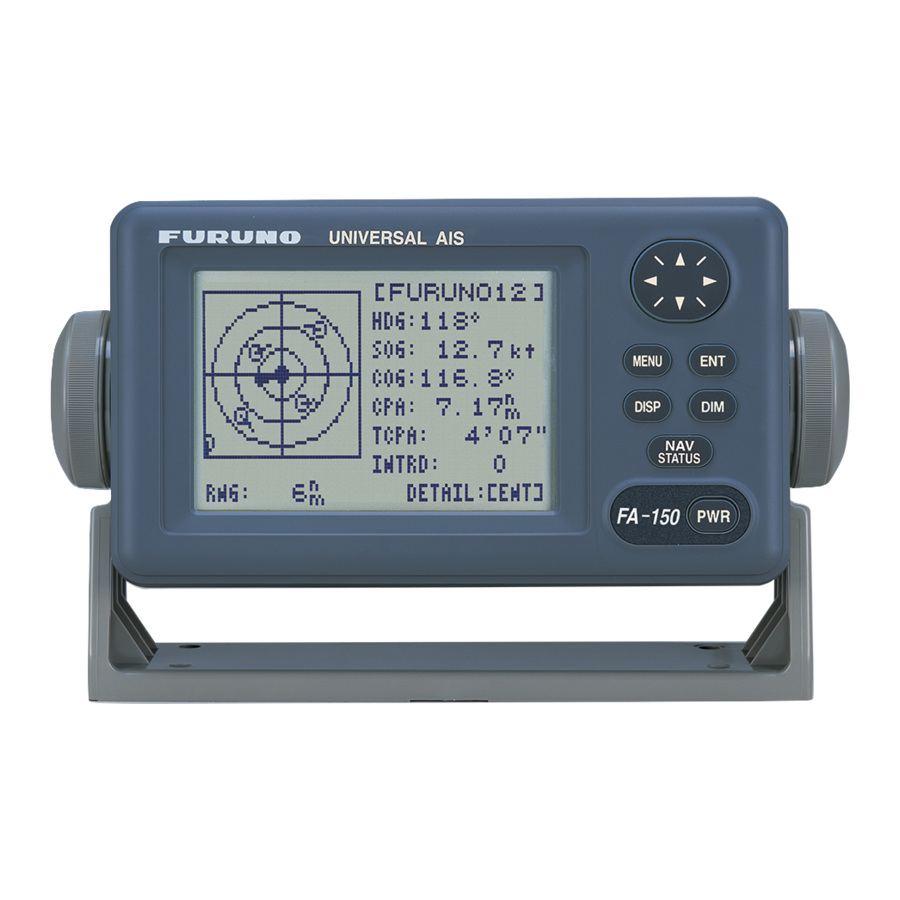
1. OPERATION 1.7.1 Plotter display The plotter display, which automatically appears after the power-on sequence, shows the name, heading, SOG, COG, CPA and TCPA of AIS-equipped ships, AIS-SARTs, etc. within the range selected. The number of dangerous targets is also indicated. Data for ship target A target marker (hollow triangle) indicates the presence of a vessel equipped with AIS in a certain location and course. - Page 24 1. OPERATION Operations on the plotter display 1. Press the DISP key to show the plotter display. 2. Use ▼ or ▲ to select the range. The available ranges are (in nm) 0.125, 0.25, 0.5, 0.75, 1.5, 3, 6, 12, and 24. 3.
-
Page 25: Target List (Displaying Target Data)
Target list (displaying target data) 1. At the plotter display, press the DISP key to show the TARGET LIST, which lists all AIS targets and AIS-SARTs being detected by the FA-150. Note 1: The dangerous target list appears when there are dangerous targets. - Page 26 1. OPERATION Ship info display, mobile class A 1-16...
- Page 27 1. OPERATION Ship info display, mobile class B 1-17...
- Page 28 1. OPERATION Base station display SAR (Search and Rescue) info display 1-18...
- Page 29 1. OPERATION AIS-SART info display DNGR appears when CPA/TCPA [SART INFO] of target is less than CPA/TCPA MMSI : 970010001 MMSI no. setting. If no signal is received STATUS: SART ACTIVE Status (SART ACTIVE (NAV STATUS: 14), from target, LOST appears.
- Page 30 1. OPERATION AtoN (Aid to Navigation) info display 1-20...
- Page 31 1. OPERATION The table below shows all the AtoN types and names that may appear on the AtoN INFO display. A to N type and name Name of AtoN Type DEFAULT, TYPE OF A TO N NOT SPECIFIED REFERENCE POINT RACON OFF SHORE STRUCTURE SPARE...
-
Page 32: Dangerous (Target) List
1. OPERATION 1.7.3 Dangerous (target) list You can easily find dangerous ships whose CPA and TCPA are lower than the CPA and TCPA alarm settings. 1. At the plotter display, press the DISP key to show the Target List (see section 1.7.2). - Page 33 1. OPERATION 1-23...
-
Page 34: Dynamic Data Display
1. OPERATION 1.7.5 Dynamic data display The OWN DYNAMIC DATA display shows your ship’s dynamic data, which includes time, date, ship’s position, SOG, COG, heading, ROT, position accuracy, and RAIM use. The Officer of the Watch should periodically check position, SOG and sensor information for quality. -
Page 35: Sending A Message
1. OPERATION 1.8.1 Sending a message 1. Press the MENU key to open the main menu. 2. Use ▼ or ▲ to select MSG then press the [MSG] ENT key. CREATE MSG TX LOG RX LOG 3. CREATE MSG is selected; press the ENT [CREATE MSG] key. -
Page 36: Receiving Messages
1. OPERATION 12. RETRY TIMES is selected; press the ENT key. If the ADRS TYPE is BROADCAST go to step 14. 13. For ADRS CAST, enter the number of times to re-transmit a message (0-3) then press the ENT key. 14. - Page 37 1. OPERATION 1. Press any key to erase the message. 2. Press the MENU key to show the main menu. 3. Select MSG then press the ENT key. 4. Select RX LOG then press the ENT key. [RX LOG] 03/MAY 13:25 NEW Date and time [UTC] FROM: 4310199111 MMSI of sender...
-
Page 38: Tx And Rx Message Logs
1.8.3 TX and RX message logs The FA-150 stores the latest 20 each of transmitted and received messages in respective message logs. When a log becomes full, the oldest message in the log is automatically deleted to make room for the latest. -
Page 39: Regional Operating Channels
1. OPERATION Regional Operating Channels AIS operates primarily on two dedicated VHF channels, CH 2087 and CH2088. Where these channels are not available regionally, the AIS is capable of being automatically switched to designated alternate channels by means of a message from a shore facility. -
Page 40: Displaying, Editing Regional Operating Area Status
1. OPERATION 1.9.2 Displaying, editing regional operating area status You may display the status of regional operating areas currently memorized in the equipment. Nine of any combination of AIS message from shore-based AIS, DSC message, manual settings and commands from ECDIS or a PC may be registered and one will be HIGH SEA. - Page 41 1. OPERATION 7. Select power desired then press the ENT key. 8. CH NO. CH-A is selected; press the ENT key. 9. Select channel number for CH-A then press the ENT key. 10. CH NO. CH-B is selected; press the ENT key. 11.
-
Page 42: Enabling/Disabling Alarm Buzzer, Key Beep
1. OPERATION 23. Press the MENU key. The prompt shown right SAVE CHANNEL. appears. ARE YOU SURE? 24. Press ◄ to select YES then press the ENT key. Note: If a combination other than that shown in the table at step 13 is selected, the message “ILLEGAL MODE WAS SELECTED PRESS ANY KEY.”... - Page 43 (code, see next page) appear. Press the ENT key to send the data, or press any key other than ENT to send no data. The screen then changes according to your selection. [RECEIVED LR] [LR RESPONSE] MMSI: 431456789 MMSI: 431456789 NAME: FURUNO NAME: FURUNO Press key Information requested RESPONSE? (See table...
-
Page 44: Msg27 Tx
1. OPERATION Codes used in long range messages Code Meaning Ship name, call sign, IMO number Date message created Position Course over ground Speed over ground Waypoint, ETA Draft Ship type, Load Ship length, width, type Number of crew 1.11.2 MSG27 TX You can send own ship data to a satellite via the AIS VHF communication link. -
Page 45: Pilot Plug (Option)
Panama Canal and the Saint Lawrence Seaway. The specifications for the pilot plug are as shown below. Baudrate: 38400 bps Note: The following setting is required for the FA-150. If the pilot does not function, check these settings. Menu Setting... -
Page 46: Viewing Initial Settings
1. OPERATION 1.13 Viewing Initial Settings The INITIAL SETTINGS menu, which is locked with a password, is where the installer enters ship’s MMSI, internal and external antenna positions, ship type and I/O port settings. You can view the settings on this menu as follows. 1. -
Page 47: Inland Ais Operation
INLAND AIS OPERATION This section provides the operating procedures for the Inland AIS feature, which allows use of the AIS transponder on inland waterways or the open sea. Only those procedures that are different from the Class A AIS transponder are presented. -
Page 48: Selecting Ais Mode
2. INLAND AIS Selecting AIS Mode The Inland AIS has two operating modes: Inland (inland waterways) and SOLAS (SOLAS compliant class A AIS transponder). Select desired mode as follows: 1. Press the NAV STATUS key to open the NAV STATUS menu. [NAV STATUS] NAV STATUS: AIS MODE:... -
Page 49: Entering Voyage-Related Data
2. INLAND AIS Entering Voyage-Related Data Before you embark on a voyage using Inland AIS, set the various voyage related data (see the list below) on the NAV STATUS menu. • Destination • No. of persons • Arrival time • Length and beam of ship •... - Page 50 2. INLAND AIS 4. Press the ENT key. Enter destination then press the ENT key. You can use up to 20 alphanumeric characters, and enter 20 destinations. (For how to enter alphanumeric characters, see “Entering alphanumeric data” on page 1-6.) Note 1: Each of the characters shown below counts as three characters.
- Page 51 2. INLAND AIS 17. Select type of vessel/cargo, referring to the table on page 1-10, then press the ENT key. Note 1: Only the second digit for the type of vessel is entered here; the first digit is entered on the initial settings menu, during installation. Note 2: When “Tanker”...
- Page 52 2. INLAND AIS 29. Enter the total number of persons (sum of crew, passengers and shipboard personnel) onboard then press the ENT key. Note: NO. OF PERSONS is sent in IFM16 messages. 30. Press ► to go to the LENGTH&BEAM sub-menu. [LENGTH&BEAM] LENGTH OF SHIP BEAM OF SHIP:...
- Page 53 2. INLAND AIS 35. HAZARDOUS CARGO is selected; press the ENT key. NUMBER OF CONES 0 NUMBER OF CONES 1 NUMBER OF CONES 2 NUMBER OF CONES 3 B-FLAG UNKNOWN 36. If your ship is carrying hazardous cargo, "cones" (max. 3) have to be shown on the mast, in daylight with cones and nighttime with blue lights.
-
Page 54: Static Data
“OWN STATIC DATA”. Use ▼ or ► to go forward, ▲ or ◄ to go back. [STATIC DATA] MMSI no. MMSI : 123456789 Name of ship NAME : FURUNO VOYAGER Call sign CALL SIGN: ZL6DEF1 IMO no. IMO NO. : 9241062* ENI no. - Page 55 2. INLAND AIS...
-
Page 56: Dynamic Data
2. INLAND AIS Dynamic Data The DYNAMIC DATA display shows your ship’s dynamic data, which includes date, time, ship’s position, etc. To show these displays, press the DISP key three times at the plotter display. The Officer of the Watch should periodically check position, speed over ground and sensor information for quality. -
Page 57: Details Ship Display (Mobile Class A)
See section 1.7.2 for how to show this display. [SHIP INFO] "DNGR" (DANGER) appears MMSI [A] : 431099806 MMSI no. (in reverse video) when a NAME : FURUNO* Name of target's CPA and TCPA ship are lower than the CPA/TCPA CALL SIGN : ZL6DEF1* Call sign setting. - Page 58 No. of persons in total Note 1: BLUE SIGN information (contained in message type 1) is displayed when the FA-150 receives an RFM10* message type 6 (inland ship and voyage related data) or type 8 (safety-related message). When this happens, "BLUE SIGN"...
-
Page 59: Inland Ais Specific Messaging
2. INLAND AIS Inland AIS Specific Messaging 2.7.1 Text message 1. Press the MENU key to open the menu. 2. Select MSG then press the ENT key. [MSG] TEXT ETA/RTA NO. OF PERSONS EMMA WARNING WATER LEVEL 3. TEXT is selected; press the ENT key. [TEXT] CREATE MSG TX LOG... - Page 60 2. INLAND AIS 8. Select MSG TYPE then press the ENT key. SAFETY NORMAL 9. Select message type: NORMAL (message other than safety) or SAFETY (important navigational or meteorological warning). Press the ENT key. 10. CHANNEL is selected; press the ENT key. ALTERNATE BOTH A &...
-
Page 61: Eta And Rta Messages
2. INLAND AIS 2.7.2 ETA and RTA messages The purpose of an ETA message is to apply for a time slot at a lock, bridge or terminal. (Hereafter "lock" refers to lock, bridge or terminal.) The message contains your ship's ETA at the lock, air draught, the number of assisting tugboats required and the particulars of the lock (country code, location code, etc.). - Page 62 2. INLAND AIS 6. MMSI is selected; press the ENT key. 7. Enter the MMSI of the lock/bridge/terminal you want to pass through then press the ENT key. 8. CHANNEL is selected; press the ENT key. ALTERNATE BOTH A & B 9.
- Page 63 2. INLAND AIS 18. Press the MENU key twice to return to the CREATE MSG menu. 19. Select SET ETA then press the ENT key. [SET ETA] The date and time format are shown as UTC (Coordinated Universal Time) or LT (Local DATE[UTC] - - / - - - TIME[UTC]...
-
Page 64: No. Of Persons Message
2. INLAND AIS 5. Select the message then press the ENT key. Lock Status - Operational - Limited Operation* - Out of Order [RTA LOG] [RTA LOG] - Not Available STATUS COUNTRY CODE: LIMITED OPERATION LOCATION CODE: Date and time RTA: 05/JUN 12:32 UTC** FAIRWAY NO.:... - Page 65 2. INLAND AIS 6. ADRS TYPE is selected; press the ENT key. BROAD CAST ADRS CAST Select ADRS CAST to send a message to a specific AIS-equipped ship or authority, or BROAD CAST to send a message to all AIS-equipped ships within broadcasting range.
-
Page 66: Emma Warning Message
2. INLAND AIS 2.7.4 EMMA warning message EMMA (European Multiservice Meteorological Awareness) warnings are sent by base stations to skippers to inform them of special meteorological situations. EMMA does not provide continuous weather information, but only warnings of wind, rain, snow and ice, thunderstorm, fog, extreme temperatures (low and high), flood, fire in the forest. - Page 67 2. INLAND AIS Item Description TYPE FI: Fire in the Forests FO: Fog FL: Flood HT: High Temperature LT: Low Temperature RA: Rain SN: Snow and Ice TH: Thunderstorm WI: Wind Units of measurement are fixed as follows: • km/h (wind) •...
-
Page 68: Water Level Message
2. INLAND AIS 2.7.5 Water level message The water level message is sent by base stations to inform skippers about actual water levels in their area. It is additional short-term information to the water levels distributed via Notices to Skippers. The message contains the country code(location), gauge ID and water level. - Page 69 2. INLAND AIS 5. Select a message then press the ENT key. Below are sample TX log messages. [TX ADDRESSED MSG] [TX BROADCAST MSG] CHANGING COURSE TO CHANGING COURSE TO 357 DEGREES AT 357 DEGREES AT 12:35. 12:35. QUIT[MENU] QUIT[MENU] TX addressed message TX broadcast message [ETA LOG]...
-
Page 70: Viewing Initial Settings
2. INLAND AIS 4. Select the message to view then press the ENT key. Below are examples of text and RTA messages. For EMMA warning and water level messages, see section 2.7.4 and 2.7.5, respectively. [RX ADDRESSED MSG] [RX BROADCAST MSG] WILL CHANGE COURSE STORM WARNING FOR TO 352 DEGREES AT... -
Page 71: Selecting Menu Language
2. INLAND AIS Selecting Menu Language You can select the language for menu window among English, French, Dutch or German. 1. Press the MENU key to open the menu. 2. Select USER SETTINGS then press the ENT key. 3. Select LANGUAGE (on page 2) then press the ENT key. [USER SETTINGS] LANGUAGE ENGLISH... -
Page 72: Selecting Units Of Measurement
2. INLAND AIS 2.10 Selecting Units of Measurement You can select the units of measurement for distance, length and speed. 1. Press the MENU key to open the menu. 2. Select USER SETTINGS then press the ENT key. 3. Select RANGE CPA UNITS, SOG UNITS or LENGTH UNITS (on page 2) as appropriate then press the ENT key. -
Page 73: Maintenance, Troubleshooting
MAINTENANCE, TROUBLESHOOTING NOTICE WARNING Do not apply paint, anti-corrosive sealant ELECTRICAL SHOCK HAZARD or contact spray to coating or plastic Do not open the equipment. parts of the equipment. Only qualified personnel Those items contain organic solvents that should work inside the can damage coating and plastic parts, equipment. -
Page 74: Replacement Of Fuse, Resetting The Breaker
3. MAINTENANCE, TROUBLESHOOTING Replacement of Fuse, Resetting the Breaker 3.2.1 Replacement of fuse The power cable for the monitor unit contains a 3A fuse which protects the equipment from overvoltage, reverse polarity and equipment fault. If the power cannot be turned on, check if the fuse has blown. If the fuse has blown, find the cause before replacing the fuse. -
Page 75: Troubleshooting
• Check the GPS antenna for damage. No position data • Check the GPS antenna cable and its connectors. Diagnostics The FA-150 provides diagnostic tests to check the monitor unit and transponder unit for proper operation. 3.4.1 Monitor unit test The monitor unit test shows program no., and checks the ROM, RAM, LCD and... - Page 76 3. MAINTENANCE, TROUBLESHOOTING 3. MONITOR TEST is selected; press the ENT key. The test program automatically proceeds in the sequence shown below. XX.XX = Program version no. [MONITOR TEST] [MONITOR TEST] BOOT NO.: 2450020-XX.XX BOOT NO.: 2450020-XX.XX PROG NO.: 2450021-XX.XX PROG NO.: 2450021-XX.XX CONT : : OK...
-
Page 77: Transponder Test
3. MAINTENANCE, TROUBLESHOOTING 3.4.2 Transponder test The transponder test consists of two tests: memory test and internal GPS receiver test. Memory test The memory can be checked for proper operation and the program number displayed as follows: 1. Press the MENU key to open the main menu. 2. - Page 78 3. MAINTENANCE, TROUBLESHOOTING Internal GPS test The internal GPS receiver can be checked for proper operation as follows: 1. Press the MENU key to open the main menu. 2. Select DIAGNOSTICS then press the ENT key. 3. Select TRANSPONDER TEST then press the ENT key. 4.
-
Page 79: Power On/Off History
3. MAINTENANCE, TROUBLESHOOTING 3.4.3 Power on/off history The PWR ON/OFF HISTORY log shows the date and time of the latest 30 power-ons and power-offs. If the interval between power-off and power-on is less than 15 minutes those times are not shown. 1. -
Page 80: Alarm Status
3. MAINTENANCE, TROUBLESHOOTING Alarm Status The alarm sounds for equipment error and is accompanied by a flashing popup indication. Press any key to silence the alarm and erase the popup. To see which alarm(s) has been violated, display the ALARM STATUS log as shown below. -
Page 81: Error And System Messages
3. MAINTENANCE, TROUBLESHOOTING Error and System Messages The FA-150 displays the following error and system messages to alert you to errors and events. Error and system messages and their meanings Message Meaning CAN’T DISPLAY INVALID DATA No position data. CAN’T DISPLAY OVER LAT85°... - Page 82 3. MAINTENANCE, TROUBLESHOOTING OUT OF RANGE! 0-65535 Invalid port number entered. OUT OF RANGE! 10-30 Invalid NavNet port number entered. OUT OF RANGE! BEAM:0-100 Invalid beam of ship entered. OUT OF RANGE! CH-A(CH-B) Invalid channel entered. DOESN'T EXIST OUT OF RANGE! CPA:0-6.00 Invalid CPA range entered.
-
Page 83: Gps Monitor
3. MAINTENANCE, TROUBLESHOOTING GPS Monitor The GPS monitor display shows information about the built-in GPS receiver, including position, speed over ground, course over ground, date, time, mode position accuracy, position-fixing status and RAIM status. 1. Press the MENU key to open the menu. 2. -
Page 84: Displaying Sensor Status
3. MAINTENANCE, TROUBLESHOOTING Displaying Sensor Status The SENSOR STATUS screen shows sensor status. 1. Press the MENU key. 2. Select SENSOR STATUS then press the ENT key. [SENSOR STATUS] Sensor status message UTC CLOCK LOST QUIT[MENU] 3. Press the DISP key to close the display. Sensor status messages and their meanings Sensor Status Message Meaning... -
Page 85: Restoring Default Settings
3. MAINTENANCE, TROUBLESHOOTING Restoring Default Settings You may clear all or specific settings to start afresh with default settings. When all data is cleared, the default settings for all items in the INIT SETTING and SYSTEM SETTINGS sub-menus are restored. GPS data is also cleared; however, MMSI and IMO numbers, ship’s name and call sign are not cleared. -
Page 86: Ais-Sart Test Indication In Target List
3.10 AIS-SART Test Indication in Target List The FA-150 can confirm if an AIS-SART is working properly. This test requires message 1 data (MMSI No. 97 XXXXXXX, NAV STATUS: 15). Note that this setting is turned off when the power is turned off. -
Page 87: Appendix
APPENDIX Menu Tree - Class A AIS [MENU] key CREATE MSG SET MSG TYPE ADRS TYPE TX LOG SET MSG (BROAD CAST, ADRS CAST) RX LOG SEND MSG MMSI MSG TYPE (NORMAL, SAFETY) SENSOR STATUS (Display sensor status.) CHANNEL (ALTERNATE, BOTH A & B, A, B) INTERNAL GPS (Displays data about internal GPS receiver.) RETRY TIMES (0-3) USER SETTINGS... - Page 88 APPENDIX (Continued from previous page) CHANNEL VIEW CHANNEL (View power and channel settings of channel in use.) SETTINGS Press [ENT] key to display. SELECT NO. (0-9) EDIT CHANNEL TIME (UTC) FROM MMSI (HIGH SEA, MMSI, EMPTY) TYPE (HIGH SEA, AIS, PI, DSC, MANUAL, EMPTY) FROM MMSI POWER (1W, 12.5W)
-
Page 89: Menu Tree - Inland Ais
APPENDIX Menu Tree - Inland AIS [MENU] key TEXT CREATE MSG SET MSG TYPE ADRS TYPE (BROAD CAST, ADRS CAST) ETA/RTA TX LOG SET MSG MMSI NO. OF PERSONS RX LOG SEND MSG MSG TYPE EMMA WARNING CREATE MSG SET MSG TYPE (NORMAL, SAFETY) WATER LEVEL CHANNEL... - Page 90 APPENDIX (Continued from previous page) MODE (STANDARD, MONITOR, SERVICE, DISABLE) * Shown when IP ADDRESS (000.000.000.000 - 255.255.255.255; 172.031.024.001) optional LAN kit PORT* SUB NET MASK (000.000.000.000 - 255.255.255.255; 255.255.000.000) is installed. PORT NO. (0 - 65535; 10000) IP ADDRESS (000.000.000.000 - 255.255.255.255; 172.031.024.001) SUB NET MASK (000.000.000.000 - 255.255.255.255;...
-
Page 91: Parts List
This equipment contains complex modules in which fault diagnosis and repair down to component level are not practical (IMO A.694(17)/8.3.1). Only some discrete components are used. FURUNO Electric Co., Ltd. believes identifying these components is of no value for shipboard maintenance;... -
Page 92: Parts Location
APPENDIX Parts Location Monitor unit CPU Board 24P0062 Monitor unit, rear cover opened Transponder unit MOT Board 24P0036 TX Board 24P0032 PWR Board 24P0037 Transponder unit, top cover removed AP-6... - Page 93 APPENDIX GPS Receiver GN-8093 GPSTB Board MAIN Board 24P0043 24P0035 RX2 Board 24P0033 RX1 Board 24P0033 DSC Board 24P0033 Transponder unit, bottom cover removed AP-7...
-
Page 94: Digital Interface (Iec 61162-1 Edition 4, Iec 61162-2
APPENDIX Digital Interface (IEC 61162-1 Edition 4, IEC 61162-2) Sentence data Input sentences ABM, ACA, ACK, AIR, BBM, DTM, GBS, GGA, GLL, GNS, HDT, LRF, LRI, OSD, PIWWIVD, PIWWSPW, PIWWSSD, PIWWVSD, RMC, ROT, SSD, THS, VBW, VSD, VTG Output sentences ABK, ACA, ACS, ALR, LRF, LR1, LR2, LR3, TXT, PIWWSPR, VDM, VDO Transmission interval ABK: With each event... - Page 95 APPENDIX Serial interface I/O circuit COM1, 2, 3 port Baud rate selectable from 4800 and 38400 (bps). 110Ω COM1_ JP LTC1535C COM1_ JP COM1_ RD_ B COM1_ RD_ A COM1_ TD_ B COM1_ TD_ A GND 2 GND_ ISO COM4, 5 port Baud rate selectable from 4800 and 38400 (bps).
- Page 96 APPENDIX DISP port Baud rate selectable from 4800 and 38400 (bps). LTC1535C 110Ω DISP_RD_B DISP_RD_A DISP_TD_B DISP_TD_A GND2 GND_ISO Blue Sign port TLP181 270 ohm Blue Sign_H Blue Sign_C Sentence description Input sentences ABM - Addressed binary and safety related message !**ABM, x, x, x, xxxxxxxxx, x, x.x, s--s, x, *hh<CR><LF>...
- Page 97 APPENDIX ACK - Acknowledge alarm $**ACK,xxx,*hh<CR><LF> 1. Local alarm number (identifier) (000 - 999) AIR - AIS interrogation request $**AIR,xxxxxxxxx,x.x,x,x.x,x,xxxxxxxxx,x.x,x, a, x.x, x.x, x.x *hh<CR><LF> 2 3 4 5 7 8 9 10 11 12 1. MMSI of interrogated station 1 2.
- Page 98 APPENDIX GBS - GNSS satellite fault detection $**GBS, hhmmss.ss, x.x, x.x, x.x, xx, x.x, x.x, x.x h, h, *hh<CR><LF> 8 9 10 1. UTC time of GGA or GNS fix associated with this sentence 2. Expected error in latitude (0.0 - 999.9) 3.
- Page 99 APPENDIX GNS - GNSS fix data $**GNS,hhmmss.ss,llll.ll,a,IIIII.II,a,c--c,xx,x.x,x.x,x.x,x.x,x.x,a*hh<CR><LF> 7 8 9 10 11 12 13 1. UTC of position (no use) 2. Latitude (0.00000 - 9000.00000) 3. N/S 4. Longitude (0.00000 - 18000.00000) 5. E/W 6. Mode indicator A=Autonomous D=Differential E=Estimated Mode F=Float RTK M=Manual Input Mode N=No fix P=Precise R=Real Time Kinematic S=Simulator Mode 7.
- Page 100 APPENDIX OSD - Own ship data $**OSD, x.x, A, x.x, a, x.x, a, x.x, x.x, a *hh<CR><LF> 5 6 7 1. Heading, degrees true (0.00 - 360.00) 2. Heading status (A=data valid, V=data invalid) 3. Vessel course, degrees true (0.00 - 359.99) 4.
- Page 101 APPENDIX SSD - UAIS ship static data $**SSD,c--c,c--c,xxx,xxx,xx,xx,c, aa*hh<CR><LF> 5 6 7 8 1. Ship's call sign (1 - 7 characters) 2. Ship's name (1 - 20 characters) 3. Pos. ref. point distance, "A," from bow (0 - 511 Meters) 4.
- Page 102 APPENDIX VTG - Course over ground and ground speed $--VTG, x.x, T, x.x, M, x.x, N, x.x, K, a,*hh <CR><LF> 1. Course over ground, degrees (0.0 - 359.9) 2. T=True (fixed) 3. (No use) Course over ground, degrees (0.0 - 359.9) 4.
- Page 103 APPENDIX LR1 - Long-range reply with destination for function request "A" $**LR1,x,xxxxxxxxx,xxxxxxxxx,c--c,c--c,xxxxxxxxx*hh<CR><LF> 1. Sequence number 2. MMSI of responder 3. MMSI of requester (reply destination) 4. Ship's name (1 - 20 characters) 5. Call sign (1 - 7 characters) 6. IMO number, (9-digit number) LR2 - Long-range reply for function requests "B, C, E, and F"...
- Page 104 APPENDIX VDM - VHF data-link message $**VDM,x,x,x,x,s--s,x,*hh<CR><LF> 1 2 3 4 5 6 1. Total number of sentences needed to transfer the message (1 to 9) 2. Message sentence number (1 to 9) 3. Sequential message identifier (0 to 9, NULL) 4.
- Page 105 APPENDIX PIWWSSD - Inland waterway static ship data $PIWWSSD CCCCCCCC, xxxx, xxxx, xxxx, x, x, x, hh<CR><LF> 5 6 7 1. ENI no. (00000000-9999 9999) 2. ERI ship type (0-9999) 3. Length of ship (0.0-800.0(m)) 4. Beam of ship (0.0-100.0(m)) 5.
-
Page 106: Vhf Channel List
APPENDIX VHF Channel List International mode Ch No. Freq. Ch No. Freq. Ch No. Freq. Ch No. Freq. 1001 156.05 1088 157.425 156.8875 2079 161.575 1002 156.1 1201 156.0625 1278 156.9375 2080 161.625 1003 156.15 1202 156.1125 1279 156.9875 2081 161.675 1004 156.2... - Page 107 APPENDIX USA mode Ch No. Freq. Ch No. Freq. Ch No. Freq. Ch No. Freq. 1001 156.05 1088 157.425 156.8875 2079 161.575 1201 156.0625 1278 156.9375 2080 161.625 1003 156.15 1202 156.1125 1279 156.9875 2081 161.675 1203 156.1625 1280 157.0375 2082 161.725 1005...
-
Page 108: Eri Codes
APPENDIX ERI Codes ERI code AIS code Full First Second Ship name (EN) code digit digit 8000 No VESSEL., 8021 MOTOR TANKER , LIQUID CARGO, 8022 MOTOR TANKER , LIQUID CARGO, 8023 MOTOR TANKER , DRY CARGO AS IF LIQUID (E.G.CEMENT) 8050 MOTOR FREIGHTER 8060... -
Page 109: Terminology, Units, Symbols
APPENDIX Terminology, Units, Symbols Terminology Abbrevia- Abbrevia- Meaning Meaning tion tion Two Dimensional Positioning Detail Three Dimensional Positioning East Addressed Binary Message E. G for example ADRS Address EMMA European Multiservice Meteoro- logical Awareness system Automatic Identification System Unique European Vessel Identifi- cation Number ALARM Alarm... - Page 110 APPENDIX Abbrevia- Abbrevia- Meaning Meaning tion tion Local Time Read Only Memory March Rate Of Turn Maximum Requested Time of Arrival Receive MENU Menu South Minimum SOG/COG Minimum Keyboard Display Search And Rescue MMSI Maritime Mobile Services Identity SDRAM Synchronous Dynamic RAM number Mother Board Select...
- Page 111 APPENDIX Symbols Symbol Meaning Sleeping AIS targets Selected AIS targets AIS-SART (Search and Rescue Transmitter) Selected AIS-SART Icons Icon Meaning Base station SAR(Search and Rescue) Aid to Navigation AIS-SART − [/] [ ] [\] [|] in turn Normal Operation AP-25...
-
Page 112: Specifications
FURUNO FA-150 SPECIFICATIONS OF U-AIS TRANSPONDER -150 TRANSPONDER UNIT TX/RX frequency 156.025 MHz to 162.025 MHz Output power 1W or 12.5 W selectable Impedance 50 ohms DSC receiver CH70 fixed, 156.525 MHz, G2B, 1200 bps Bandwidth 25 kHz/ 12.5 kHz... - Page 113 FURUNO FA-150 POWER SUPPLY Transponder unit 12-24 VDC: 7-3.5 A Monitor unit 12-24 VDC: 0.3-0.15 A AC/DC power supply unit (PR-240, option) 100-115/200-230 VAC, 1 phase, 50/60 Hz ENVIRONMENTAL CONDITION Ambient temperature GPS/VHF antenna -25°C to +55°C (storage: -25°C to +70°C) Other units -15°C to +55°C...
-
Page 114: Index
INDEX mobile class B .......... 1-17 SAR ............1-18 AIS-SART test indication ......3-14 Initial settings Alarm status............ 3-8 class A............1-36 Alarm status display ........1-24 Inland AIS........2-24, 2-25 Inland AIS activating ............ 2-1 Breaker reset ..........3-2 details display........... - Page 115 INDEX PWR key............1-2 Text message class A ............1-24 inland AIS ..........2-13 RTA message (Inland AIS)......2-17 Transponder test ..........3-5 RX logs Troubleshooting..........3-3 class A ............1-28 TX logs inland AIS ..........2-23 class A ............1-28 inland AIS ..........2-22 TX on/off history ..........
Need help?
Do you have a question about the FA-150 and is the answer not in the manual?
Questions and answers
Me aparece en display UTC TX ANT que significa
On the Furuno FA-150 display:
- UTC refers to Universal Coordinated Time.
- TX indicates a transmission or transmit status.
- ANT means there is an antenna VSWR (Voltage Standing Wave Ratio) trouble.
So, UTC TX ANT likely means that at a specific UTC time, a transmission occurred or was attempted, and there was an antenna-related issue (VSWR trouble).
This answer is automatically generated