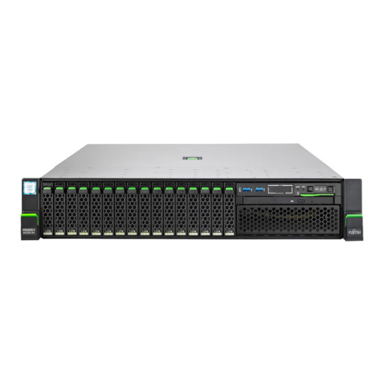
Sign In
Upload
Manuals
Brands
Fujitsu Manuals
Server
PRIMERGY RX2520 M4
Fujitsu PRIMERGY RX2520 M4 Manuals
Manuals and User Guides for Fujitsu PRIMERGY RX2520 M4. We have
2
Fujitsu PRIMERGY RX2520 M4 manuals available for free PDF download: Upgrade And Maintenance Manual, Operating Manual
Fujitsu PRIMERGY RX2520 M4 Upgrade And Maintenance Manual (456 pages)
Brand:
Fujitsu
| Category:
Server
| Size: 11.93 MB
Table of Contents
Table of Contents
7
Introduction
23
Notational Conventions
24
Before You Start
25
Classification of Procedures
27
Customer Replaceable Units (CRU)
27
Upgrade and Repair Units (URU)
28
Field Replaceable Units (FRU)
29
Average Task Duration
30
Documents You Need at Hand
31
Tools You Need at Hand
31
Important Information
33
Safety Instructions
33
Energy Star
41
CE Conformity
42
FCC Class a Compliance Statement
42
Environmental Protection
43
Locating the Defective Server
45
Basic Hardware Procedures
45
Using Diagnostics Information
45
Determining the Error Class
46
Global Error Indicator
46
Customer Self Service (CSS) Indicator
46
Locating the Defective Component
47
Local Diagnostic Indicators on the Front
47
Local Diagnostic Indicators on the System Board
47
Shutting down the Server
48
Disconnecting the Power Cord
49
Getting Access to the Component
50
Extending the Server out of the Rack
50
Removing the Server from the Rack
52
Removing the Top Cover
54
Reassembling
55
Installing the Top Cover
55
Installing the Server in the Rack
56
Sliding the Server into the Rack
58
Connecting the Power Cord
59
Switching on the Server
60
Handling the Air Duct
61
Removing the Air Duct
61
Installing the Air Duct
62
Handling the Fan Holder
63
Removing the Fan Holder
63
Installing the Fan Holder
64
Handling the Crossbar
65
Removing the Crossbar
65
Installing the Crossbar
66
Basic Software Procedures
67
Starting the Maintenance Task
67
Suspending Bitlocker Functionality
67
Disabling the Boot Watchdog (Irmc S5)
68
Removing Backup and Optical Disk Media
69
Verifying and Configuring the Backup Software Solution
70
Switching on the ID Indicator
70
Completing the Maintenance Task
72
Updating or Recovering the BIOS and Irmc S5
72
Updating or Recovering the BIOS
72
Updating or Recovering the Irmc
73
Verifying System Information Backup/Restore
74
Updating Expansion Card Firmware (Irmc S5)
76
Enabling Option ROM Scan
77
Reconfiguring the Backup Software Solution
79
Resetting the Boot Retry Counter
79
Viewing the Boot Retry Counter
79
Resetting the Boot Retry Counter
80
Resetting the Error Status after Replacing Memory Modules or Cpus
81
Memory Modules
81
Cpus
82
Enabling Replaced Components in the BIOS
84
Enabling the Boot Watchdog (Irmc S5)
84
Verifying the Memory Mode
85
Verifying the System Time Settings
86
Viewing and Clearing the System Event Log (SEL)
86
Viewing the SEL
86
Clearing the SEL
88
Updating the NIC Configuration File in a Linux and Vmware Environment
89
Resuming Bitlocker Functionality
89
Performing a RAID Array Rebuild
90
Looking up Changed MAC/WWN Addresses
91
Looking up MAC Addresses
91
Looking up WWN Addresses
92
Using the Chassis ID Prom Tool
93
Configuring LAN Teaming
94
After Replacing/Upgrading LAN Controllers
94
After Replacing a System Board
95
Switching off the ID Indicator
95
Performing a Fan Test
96
Power Supply Unit (PSU)
99
Basic Information
99
PSU Configurations
100
Assembly Rules
100
Redundant Power Supply
101
Installing a PSU
102
Preliminary Steps
102
Removing the Dummy Cover
102
Installing a PSU
103
Concluding Steps
104
Removing a PSU
104
Preliminary Steps
104
Note for Servers Using CMA (Cable Management Arm)
104
Removing a PSU
107
Installing the Dummy Cover
108
Concluding Steps
108
Note for Servers Using CMA (Cable Management Arm)
109
Replacing a PSU
109
Preliminary Steps
109
Removing the Defective PSU
110
Installing the New PSU
110
Concluding Steps
110
Power Distribution Board
111
Installing the Power Distribution Board
111
Preliminary Steps
111
Installing the Power Distribution Board
112
Concluding Steps
114
Removing the Power Distribution Board
114
Preliminary Steps
114
Removing the Power Distribution Board
115
Concluding Steps
116
Replacing the Power Distribution Board
116
Preliminary Steps
116
Concluding Steps
117
Installing the Power Distribution Board
117
Removing the Power Distribution Board
117
Hard Disk Drive (HDD) and Solid State Drive (SSD)
119
Basic Information
120
Handling the Hdds or Ssds Without Installation Frame
121
Inch HDD/SSD and 2.5-Inch Installation Frame
121
Inch HDD/SSD and 3.5-Inch Installation Frame
123
Inch HDD and 3.5-Inch Installation Frame
125
Inch HDD/SSD Configurations
127
Configuration with up to Eight HDD/SSD Modules
127
Configuration with up to 16 HDD/SSD Modules
128
Configuration with up to 24 HDD/SSD Modules
129
Configuration with Additional Pcie-Ssds
130
Installing 2.5-Inch HDD/SSD Modules
132
Preliminary Steps
132
Removing a 2.5-Inch Dummy Module
132
Installing a 2.5-Inch HDD/SSD Module
133
Concluding Steps
134
Removing 2.5-Inch HDD/SSD Modules
135
Preliminary Steps
135
Removing a 2.5-Inch HDD/SSD Module
136
Installing a 2.5-Inch Dummy Module
136
Concluding Steps
137
Replacing a 2.5-Inch HDD/SSD Module
138
Concluding Steps
139
Installing the New 2.5-Inch HDD/SSD Module
139
Removing the Defective 2.5-Inch HDD/SSD Module
139
Preliminary Steps
139
Replacing a 8X 2.5-Inch HDD Backplane
140
Preliminary Steps
140
Removing the 2.5-Inch HDD Backplane
141
Installing a 2.5-Inch HDD Backplane
142
Connecting a 2.5-Inch HDD Backplane
143
Concluding Steps
144
Installing the Second 2.5-Inch HDD Backplane
145
Preliminary Steps
145
Upgrading from 8X to 16X 2.5-Inch HDD/SSD Configuration
145
Installing Additional HDD/SSD Modules
146
Concluding Steps
146
Upgrading from 16X to 24X 2.5-Inch HDD/SSD Configuration
147
Preliminary Steps
147
Removing the Front Panel Cage
147
Installing the Front Panel on QRL
147
Installing the ID Card Holder
147
Installing the Third 2.5-Inch HDD Backplane
148
Installing Additional HDD/SSD Modules
148
Concluding Steps
148
Installing the SAS Expander Board
149
Preliminary Steps
149
Installing the SAS Expander Board Holder
150
Concluding Steps
151
Removing the SAS Expander Board Holder
152
Preliminary Steps
152
Removing the SAS Expander Board
152
Removing the SAS Expander Board
153
Concluding Steps
153
Replacing the SAS Expander Board
154
Preliminary Steps
154
Removing the Defective SAS Expander Board
154
Installing the New SAS Expander Board
154
Concluding Steps
154
Upgrading the 4X 2.5-Inch Pcie SSD Backplane
156
Preliminary Steps
156
Installing a 4X 2.5-Inch Pcie SSD Backplane
156
Connecting a 4X 2.5-Inch Pcie SSD Backplane
157
Installing Additional Pcie SSD Modules
158
Concluding Steps
158
Inch HDD/SSD Configurations
159
Configuration with up to Four HDD Modules
159
Configuration with up to Eight HDD Modules
160
Configuration with up to 12 HDD Modules
161
Installing 3.5-Inch HDD Modules
162
Preliminary Steps
162
Removing a 3.5-Inch Dummy Module
162
Installing a 3.5-Inch HDD Module
163
Concluding Steps
164
Removing 3.5-Inch HDD Modules
165
Preliminary Steps
165
Removing a 3.5-Inch HDD Module
166
Installing a 3.5-Inch Dummy Module
166
Concluding Steps
166
Replacing a 3.5-Inch HDD Module
167
Preliminary Steps
167
Removing a Defective 3.5-Inch HDD Module
168
Installing a New 3.5-Inch HDD Module
168
Concluding Steps
168
Replacing the 3.5-Inch HDD Backplanes
169
Preliminary Steps
169
Removing a 3.5-Inch HDD Backplane
170
Installing a 3.5-Inch HDD Backplane
171
Connecting a 3.5-Inch HDD Backplane
173
Concluding Steps
173
Upgrading to 8X 3.5-Inch HDD Configuration
174
Preliminary Steps
174
Installing the Second 3.5-Inch HDD Backplane
174
Installing Additional HDD/SSD Modules
175
Concluding Steps
175
Replacing the 12X 3.5-Inch HDD Backplane
176
Preliminary Steps
176
Removing the SAS Expander Board Holder
177
Removing the Defective 12X 3.5-Inch HDD Backplane
178
Installing the New 12X 3.5-Inch HDD Backplane
179
Installing the SAS Expander Board Holder
181
Concluding Steps
182
Replacing the SAS Expander Board
183
Preliminary Steps
183
Removing the Defective SAS Expander Board
183
Installing the New SAS Expander Board
185
Concluding Steps
186
Replacing the Connector Card
187
Preliminary Steps
187
Removing the Defective Connector Card
187
Installing the New Connector Card
188
Concluding Steps
188
Fans
189
Basic Information
190
Numbering of the Fan Modules
190
Replacing a Fan Module
192
Preliminary Steps
192
Removing a Defective Fan Module
192
Concluding Steps
193
Installing a New Fan Module
193
Expansion Cards and Backup Units
195
Basic Information
196
Handling Slot Brackets
198
Installing a Slot Bracket
198
Removing a Slot Bracket
200
Handling SFP+ Transceiver Modules
201
Installing the SFP+ Transceiver Modules
201
Removing the SFP+ Transceiver Modules
204
Expansion Cards
207
Installing Expansion Cards
207
Preliminary Steps
207
Removing the Slot Cover
207
Installing an Expansion Card
208
Concluding Steps
212
Removing an Expansion Card
213
Preliminary Steps
213
Removing Expansion Cards
213
Installing the Slot Cover
214
Concluding Steps
214
Replacing Expansion Cards
215
Preliminary Steps
215
Removing the Expansion Card
215
Installing the Expansion Card
216
Concluding Steps
216
Removing the TFM
217
Replacing a TFM
217
Preliminary Steps
217
Installing the TFM
219
Concluding Steps
221
Flash Backup Unit (FBU)
222
Installing an FBU
222
Preliminary Steps
222
Preparing the FBU02 (Ep4X0I)
223
Preparing the FBU345 (Ep5X0I)
224
Installing the FBU
225
Concluding Steps
226
Removing an FBU
227
Preliminary Steps
227
Removing the FBU with the Holder
228
Disconnecting the FBU Cable from the FBU
229
Removing the FBU02 (Ep4X0I) from the Holder
229
Concluding Steps
230
Replacing an FBU
230
Preliminary Steps
230
Removing the Defective FBU
230
Installing the New FBU
231
Concluding Steps
231
Main Memory
233
Basic Information
234
Population Rules
236
Modes of Operation
237
Independent Channel Mode
237
Mirrored Channel Mode
238
Rank Sparing Mode (Single-Dual Rank Modules)
240
Rank Sparing Mode (Quad Rank Modules)
241
Installing Memory Modules
242
Preliminary Steps
242
Selecting the Memory Slot
242
Installing a Memory Module
242
Concluding Steps
243
Removing Memory Modules
243
Preliminary Steps
243
Removing a Memory Module
244
Concluding Steps
244
Replacing Memory Modules
245
Preliminary Steps
245
Removing a Defective Memory Module
245
Installing a New Memory Module
245
Concluding Steps
245
Processor (CPU)
247
Basic Information
248
Upgrading to 2 Cpus Configuration
251
Preliminary Steps
251
Removing the Socket Cover
252
Installing the CPU and Heat Sink
253
Upgrading the Main Memory
256
Concluding Steps
257
Replacing a CPU or Heat Sink
258
Preliminary Steps
258
Removing the Heat Sink
259
Removing the CPU
260
Applying the Thermal Paste to the CPU Surface
262
Installing the CPU and Heat Sink
263
Concluding Steps
263
Accessible Drives
265
Basic Informations
266
Preliminary Steps
267
Optical Disk Drive (ODD) for the 2.5-Inch Version
267
Installing a ODD
267
Removing the ODD Dummy Cover
268
Installing the ODD
269
Concluding Steps
272
Removing a ODD
272
Preliminary Steps
272
Removing the ODD
273
Installing the ODD Dummy Cover
275
Concluding Steps
276
Replacing a ODD
276
Preliminary Steps
276
Removing the Defective ODD
276
Installing the New ODD
276
Concluding Steps
277
Preliminary Steps
278
Installing a ODD
278
Optical Disk Drive (ODD) for the 3.5-Inch Version
278
Removing the ODD Dummy Cover
279
Installing the ODD
280
Concluding Steps
283
Removing a ODD
283
Preliminary Steps
283
Removing the ODD
284
Installing the ODD Dummy Module
285
Concluding Steps
286
Replacing a ODD
287
Preliminary Steps
287
Removing the Defective ODD
287
Installing the New ODD
287
Concluding Steps
287
Preliminary Steps
288
Installing a LTO Drive
288
LTO Drive
288
Removing the Air Grid
289
Installing the LTO Drive
290
Concluding Steps
293
Removing a LTO Drive
294
Preliminary Steps
294
Removing the LTO Drive
294
Inserting the Air Grid
297
Concluding Steps
298
Replacing a LTO Drive
299
Preliminary Steps
299
Removing the Defective LTO Drive
299
Installing the New LTO Drive
299
Concluding Steps
299
RDX Drive
300
Installing a RDX Drive
300
Preliminary Steps
300
Removing the Air Grid
301
Preparing the RDX Drive
302
Installing the RDX Drive
303
Concluding Steps
305
Removing a RDX Drive
305
Preliminary Steps
305
Removing the RDX Drive
306
Inserting the Air Grid
308
Concluding Steps
308
Installing the New RDX Drive
309
Concluding Steps
309
Replacing a RDX Drive
309
Removing the Defective RDX Drive
309
Preliminary Steps
309
Front Panel
311
Basic Information
311
Front Panel Module (2.5-Inch Version)
312
Replacing the Front Panel Module
312
Preliminary Steps
313
Removing the Front Panel Cage
313
Removing the Front Panel Module
315
Removing Cables from the Front Panel Module
316
Installing Cables to the Front Panel Module
317
Installing the Front Panel Module
318
Installing the Front Panel Cage
319
Concluding Steps
322
Front Panel Module (3.5-Inch Version)
323
Replacing the Front Panel Module
323
Preliminary Steps
323
Removing the Front Panel Module
324
Removing Cables from the Front Panel Module
326
Installing Cables to the Front Panel Module
327
Installing the Front Panel Module
328
Concluding Steps
329
Preliminary Steps
330
Front Panel on QRL
330
Replacing the Front Panel on QRL
330
Removing the Front Panel on QRL
331
Installing the Front Panel on QRL
333
Concluding Steps
335
Replacing the ID Card Holder
335
Preliminary Steps
335
Removing the ID Card Holder
336
Concluding Steps
337
Installing the ID Card Holder
337
Serial Interface
339
Installing the Serial Interface
339
Preliminary Steps
339
Breaking out the Metal Cover
340
Installing the Serial Interface
340
Concluding Steps
342
Removing the Serial Interface
343
Preliminary Steps
343
Concluding Steps
344
Replacing the Serial Interface
345
Preliminary Steps
345
Removing the Defective Serial Interface
345
Installing the New Serial Interface
345
Concluding Steps
345
System Board and Components
347
Basic Information
348
CMOS Battery
349
Replacing the CMOS Battery
349
Preliminary Steps
349
Replacing the Defective CMOS Battery
350
Concluding Steps
350
Trusted Platform Module (TPM)
351
Installing the TPM
352
Preliminary Steps
352
Concluding Steps
354
Removing the TPM
355
Preliminary Steps
355
Removing the TPM
356
Concluding Steps
358
Replacing the TPM
359
Preliminary Steps
359
Removing the Defective TPM
360
Installing the New TPM
360
Concluding Steps
360
Installing the Irmc Microsd Card
361
Preliminary Steps
361
Irmc Microsd Card
361
Concluding Steps
362
Removing the Irmc Microsd Card
362
Preliminary Steps
362
Removing the Irmc Microsd Card
363
Concluding Steps
363
Concluding Steps
364
Replacing the Irmc Microsd Card
364
Preliminary Steps
364
Ssd
365
Installing an M.2 SSD
365
Preliminary Steps
365
Installing the M.2 SSD
366
Concluding Steps
367
Software Configuration
368
Removing the M.2 SSD
369
Preliminary Steps
369
Concluding Steps
370
Replacing the M.2 SSD
371
Preliminary Steps
371
Concluding Steps
371
Software Configuration
372
Preliminary Steps
373
Installing the Dual Microsd 64GB Enterprise
373
Dual Microsd 64GB Enterprise
373
Concluding Steps
376
Removing the Dual Microsd 64GB Enterprise
377
Preliminary Steps
377
Concluding Steps
378
Replacing the Dual Microsd 64GB Enterprise
379
Concluding Steps
379
System Board
380
Replacing the System Board
380
Preliminary Steps
382
Removing the System Board
383
Installing the New System Board
384
Concluding Steps
385
Mechanical Overview
387
Server Front
387
Inch Hdds
387
Inch Hdds
388
Server Rear
389
Server Interior
390
Connectors and Indicators
391
Connectors and Indicators on the System Board
391
Onboard Connectors
391
Onboard Indicators and Controls
393
Server Front
396
Indicators on the Front Panel
396
Indicator on the ODD
399
Indicators on the Hot-Plug HDD/SSD Module
400
Server Rear
401
Connectors on the I/O Panel
401
Indicators on the I/O Panel
402
Indicators on Psus (Slide-In Units)
405
Onboard Settings
406
Minimum Startup Configuration
408
System Cabling Overview - English
414
List of Used Cables
415
List of Used Cables (Continuation)
416
Systemboard Connectors
417
Basic Cabling
418
Basic PDB Red PSU
419
Power Cabling 4/8X3.5
420
Power Cabling 12X3.5
421
Power Cabling 8/16/24X2.5
422
Power Cabling 8X2,5" + 4X2.5" Pciessd
423
HDD Cabling 4/8X3.5" SATA
424
HDD Cabling 4/8X3.5" SAS
425
HDD Cabling 4/8X3.5" Ep5X0
426
HDD Cabling 12X3.5" SAS
427
HDD Cabling 12X3.5" Ep5X0
428
HDD Cabling 8X2.5" SATA
429
HDD Cabling 8/16X2.5" SAS W/ Exp
430
HDD Cabling 8/16X2.5" SAS W/O Exp
431
HDD Cabling 8/16X2.5" Ep5X0 W/ Exp
432
HDD Cabling 8/16X2.5" Ep5X0 W/O Exp
433
HDD Cabling 24X2.5" SAS
434
HDD Cabling 24X2.5" Ep5X0 W/ Exp
435
Pciessd Cabling 8X2,5" + 4X2.5" Retimer
436
Accdrv_Odd
437
Accdrv_Rdx
438
Accdrv_Lto
439
Dual_Micro_Sd_64Gb_Enterprise
440
Pdual_Ap200
441
Serial
442
Raid Sas - Tfm Fbu02
443
RAID Ep5X0 - TFM FBU345 - HDD Signal
444
OOB Cabling 4/8X3.5
445
OOB Cabling 12X3.5
446
OOB Cabling 8/16/24X2.5
447
OOB Cabling 8/12/16X2.5" Pciessd
448
Advertisement
Fujitsu PRIMERGY RX2520 M4 Operating Manual (92 pages)
Brand:
Fujitsu
| Category:
Server
| Size: 1.81 MB
Table of Contents
Table of Contents
5
1 Introduction
9
Concept and Target Groups for this Manual
10
Documentation Overview
10
Notational Conventions
11
2 Functional Overview
13
Features
13
Server Specification
23
3 Installation Steps, Overview
33
4 Important Information
35
Safety Instructions
35
Energy Star
44
CE Conformity
44
FCC Class a Compliance Statement
45
Environmental Protection
46
5 Hardware Installation
49
Unpacking the Server
50
Installing/Removing the Server In/From the Rack
51
Connecting Devices to the Server
53
Connecting the Server to the Mains
59
Using the Cable Clamp (AC PSU)
60
Notes on Connecting/Disconnecting Cables
61
6 Starting up and Operation
63
Controls and Indicators
63
Server Front
63
Controls on the Front Panel
63
Indicators on the Control Panel
65
Indicators on the Accessible Drives / Components
68
Indicators on the HDD/SSD Modules
68
Server Rear
70
Indicators on the I/O Panel
70
Indicators on the PSU (Slide-In Unit)
74
Indicators of the System Fans
74
ID Card
75
Switching the Server on and off
77
Configuring the Server
80
Configuring the Onboard SATA Controller
80
Configuring the SAS/SATA RAID Controller
81
Configuring the Server and Installing the Operating System with the Serverview Installation Manager
82
Configuring the Server and Installing the Operating System Without the Serverview Installation Manager
83
Cleaning the Server
84
7 Property and Data Protection
85
BIOS Setup Security Functions
85
8 Troubleshooting and Tips
87
Power-On Indicator Remains Unlit
87
Server Switches Itself off
88
Screen Remains Blank
88
Flickering Stripes on Monitor Screen
89
No Screen Display or Display Drifts
89
Incorrect Date and Time
90
System will Not Boot
90
HDD Error Messages at System Boot
90
Added Drive Reported as Defective
91
Error Message on Screen
91
Expansion Cards or Onboard Devices Not Recognized
91
Temperature Warning
92
No Effect of Keyboard or Mouse
92
ODD Cannot Read Data
92
Advertisement
Related Products
Fujitsu PRIMERGY RX2520 M1
Fujitsu PRIMERGY RX2520 M5
Fujitsu PRIMERGY RX2540 M1
Fujitsu PRIMERGY RX2530 M2
Fujitsu PRIMERGY RX2560 M2
Fujitsu PRIMERGY RX2540 M4
Fujitsu PRIMERGY RX2540 M5
Fujitsu PRIMERGY RX2530 M5
Fujitsu PRIMERGY RX2530 M4
Fujitsu PRIMERGY RX2540 M7
Fujitsu Categories
Air Conditioner
Laptop
Server
Scanner
Storage
More Fujitsu Manuals
Login
Sign In
OR
Sign in with Facebook
Sign in with Google
Upload manual
Upload from disk
Upload from URL