Sign In
Upload
Manuals
Brands
Fluke Manuals
Laboratory Equipment
TIP900
Fluke TIP900 Temperature Profiling Manuals
Manuals and User Guides for Fluke TIP900 Temperature Profiling. We have
1
Fluke TIP900 Temperature Profiling manual available for free PDF download: Operating Instructions Manual
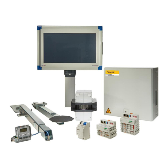
Fluke TIP900 Operating Instructions Manual (100 pages)
Wallboard Temperature Imaging & Profiling System
Brand:
Fluke
| Category:
Laboratory Equipment
| Size: 9 MB
Table of Contents
Table of Contents
4
Safety Instructions
9
Product Description
11
Figure 1: Example of Fiber Optical Link to Overcome Large Network Distances
11
System Overview and Arrangement of Components
12
Figure 2: TIP900SYS System Components, Which Have to be Integrated
12
Figure 3: Process Overview and Arrangement of TIP900 Components (Red)
12
Figure 4: Front View of the Industrial Touch-Panel PC
13
Figure 5: Rear View into the Equipped Industrial Touch-Panel PC
13
Figure 6: Options to Fix the Industrial Touch-Panel PC
14
Figure 7: Protective Housing, Equipped with Thermal Imager and Network Components
14
Figure 8: Temperature Compensation Set
15
Figure 9: Drop Gate Identification and Signaling Set
15
Technical Data
16
Specifications
16
TIP900SYS (Thermal Imager, Needs to be Mounted in Protective Housing)
16
Figure 10: Thermal Imager Mounting Locations and Dimensions
17
Figure 11: Thermal Imager Air Purge and Water Cooling Connections
17
TIP900SYS (Telescope Arms for Temperature Compensation Set)
18
Figure 12: Sensor Telescope Arm for Temperature Compensation Set
18
Figure 13: Counter Paddle Telescope Arm for Temperature Compensation Set
18
TIP900SYS (IR Temperature Sensor, Mounted Close to Kiln Discharge)
19
Figure 14: Dimensions of LTS10 Sensing Head
19
Figure 15: Spot Size Charts
19
TIP900SYS (IR Temperature Sensor Connection Box to Network)
20
Figure 16: Dimensions of RAYMI3COMME Box
21
Figure 17: Terminal Wiring for the RAYMI3COMME Box
21
TIP900SYS (Protective Housing for Thermal Imager, Network, Power
22
TIP900SYS (Option: Fiber Optic / RJ45 Ethernet Converter > 80M, 262Ft)
22
Figure 18: Protective Housing for Thermal Imager, Network Components, Power Supply
22
TIP900SYS (Touch-Panel PC with Industrial Computer Components)
23
Figure 19: Industrial Cabinet for Touch-Panel PC and Integrated Components
23
Scope of Delivery
24
Installation
25
Pre-Installation Terms and Conditions
25
Figure 20: TIP900 Definitions for Wallboard, Image Orientation and Pixel Numbering
26
Environment
27
Figure 21: TIP900 Schematic Wiring of Concerned Components
27
Installation of Protective Housing with Internal Thermal Imager
28
Mechanical Installation of the Protective Housing
28
Figure 22: Mounting of the Thermal Imager in the Protective Housing
28
Figure 23: Loose Supplied Parts for Mechanical Installation Support
29
Figure 24: Distance between Protective Housing and Wallboard Surfaces
29
Electrical Installation of the Protective Housing
30
Figure 25: Principle Diagram of Internal Wiring in Protective Housing
30
Cable Entry System
31
Figure 26: Pictures and Description of Cable Entry System
31
Installation of the Temperature Compensation Set
32
Mechanical Installation of the Temperature Compensation Set
32
Figure 27: Upper and Lower Telescope Arm Fixtures Installed after Kiln Exit
32
Figure 28: Schematic of Kiln and Deck Outfeed Arrangement
32
Electrical Installation of the Temperature Compensation Set
33
Installation of the Drop Gate Identification and Signaling Set
34
Figure 29: Drop Gate Identification and Signaling Set
34
Figure 30: Schematic of Drop Gate Wiring to Identification and Signaling Set
34
Installation of the Industrial Touch-Panel PC
35
Mechanical Installation of the Touch-Panel PC
35
Figure 31: Base Mounted Pedestal with Mounting Dimensions
35
Figure 32: Wall Mounted Swiveling Supporting Arm with Dimensions
36
Figure 33: Load Diagram for Wall Mounted Swiveling Supporting Arm
36
Figure 34: Mounting Elements for Wall Mounted Swiveling Supporting Arm with Dimensions
37
Electrical Installation of the Touch-Panel PC
38
Figure 35: Wiring Terminal Block in Touch-Panel PC
38
Operation
39
System Prerequisites, Limitations & General User Information
39
Figure 36: Created TIP900 Icons During SW Installation Process
39
Operation of Tip900 Monitoring and Defect Identification Sw
40
General Description, Assigned Screen Areas, Related Elements & Menus
40
Figure 37: Program Is Running in Supervisor Mode, 7 Domains Are Marked
40
The Program Title & Version Line and the User Mode Dependent Menu Bar Domain
41
The Program Title Line and Its Information Content
41
Figure 38: Program Is Running in Operator Mode with Restricted Rights
41
Figure 39: Program Is Running in Supervisor Mode with Administration Rights
41
The "Product Recipe" Selector in the Menu Bar
42
Figure 40: Product Recipe Selection Screen in Operator or Supervisor Mode
42
The "Edit Recipe" Selector in the Menu Bar
45
Figure 41: Edit Recipe Selection Screen in Supervisor Mode
45
The "Configuration" Selector in the Menu Bar
47
Figure 42: Application Configuration Tab Screens in Supervisor Mode
47
Figure 43: Inputs/Outputs & Temperature Compensation Tab Screens in Supervisor Mode
50
Figure 44: Scanner Tab Screen in Supervisor Mode
52
The "Maintenance" Selector in the Menu Bar
53
Figure 45: Input and Output Module Tab Screen in Supervisor Mode
53
Figure 46: Maintenance of MP150 Scanner in Supervisor Mode
54
Figure 47: Maintenance Tab of Temperature Compensation in Supervisor Mode
55
Figure 48: Dust Filter Change Confirmation, to Keep the Configured Filter Change Interval
56
The "Show Fullscreen" Selector in the Menu Bar
57
Figure 49: Process Screens: Display of Board Map
57
Figure 50: Process Screens: Display of Dryer Profile (8 Decks)
57
Figure 51: Process Screens: Boards Display of 2 Boards Per Deck
58
Figure 52: Process Screens: Temperature Curve for Min., Max., Average Temperature
58
Figure 53: Process Screens: Comparison Current Boards to Reference Boards
59
Figure 54: Process Screens: Horizontal Slice of Boards Temperature Distribution
59
Figure 55: Process Screens: Vertical Slice of Boards Temperature Distribution
60
Figure 56: Process Screens: Inspect Board Map
60
Figure 57: Process Screens: Deck Statistics of Good and Bad Boards
61
Figure 58: by Deck History of Good/Bad Boards
61
Figure 59: by Row History of Good/Bad Boards
61
The "Login Supervisor" and the "Logout Supervisor" Selectors
62
The "About" Selector in the Menu Bar
62
Figure 60: Login Mask for Supervisor Login
62
The Board Map Display Domain
63
Figure 61: Board Map Domain with Marked Sub-Domains
63
The Process Screens Display Domain
65
The Dryer Profile
65
Figure 62: the Dryer Profile of Wallboard Sets Leaving the Kiln
65
The Boards Display
66
Figure 63: the Boards Display Shows a Currently Scanned Set of Wallboards
66
The Temperature Display
67
Figure 64: Temperature Trend Display of Scanned Wallboards
67
The Reference Boards Display
68
Figure 65: the Reference Board Display Shows the Assigned References Per Dryer Deck
68
The Horizontal Slice through the Boards Map
69
Figure 66: Horizontal Slice Display Shown in the Right Display Section
69
The Vertical Slice through the Boards Map
70
Figure 67: Vertical Slice Display Shown in the Right Display Section
70
The Inspect Boards Map Display
71
Figure 68: Inspect Boards Display Shown in the Right Display Section
71
The Deck Statistics Display
72
Figure 69: Deck Statistics Display Shows the Relation of Good/Bad Produced Wallboard Sets
72
The Hardware Status Indicator Display Domain
73
The Special Function Selection Display Domain
73
Figure 70: the Hardware Status Indicators
73
Figure 71: the Special Function Selection Bar
73
The General Information Display Domain
74
The Deck History Information Display Domain
74
Figure 72: the General Info Sub-Screens
74
Figure 73: the both Deck History Sub-Screens
74
Operation in "Standard Operator" Mode
75
Figure 74: Program Is Running in Standard Operator Mode with Restricted Rights
75
Operation in "Supervisor" Mode
76
Figure 75: Program Is Running in Supervisor Mode with Administration Rights
76
Operation of Tip900_Logviewer Online/Offline Viewing SW
77
General Description of the Functionality and Assigned Screen Elements
77
Figure 76: Program Is Started, a Valid Log-File Is Opened, 6 Domains Are Marked
77
The Program Title & Version Line with the Menu Bar Domain
78
The Program Title Line and Its Information Content
78
Figure 77: TIP900 - Log Viewer Title Line and Menu Bar Selectors
78
The File Selector in the Menu Bar
79
Figure 78: TIP900 - Log Viewer File Selector in the Menu Bar
79
Figure 79: TIP900 - Log Viewer File Selector to Open a Logfile
79
Figure 80: TIP900 - Log Viewer with Selected and Opened Logfile
80
Figure 81: TIP900 - Log Viewer to Open a Logfile by Date Filtering
80
Figure 82: TIP900 - Log Viewer to Reload an Opened Logfile
81
Figure 83: TIP900 - Log Viewer to Close an Opened Logfile
81
Figure 84: TIP900 - Log Viewer with Selected and Opened Logfile
82
Figure 85: TIP900 - Log Viewer to Open a Logfile by Date Filtering
82
Figure 86: TIP900 - Log Viewer to Reload an Opened Logfile
83
Figure 87: TIP900 - Log Viewer to Close an Opened Logfile
83
Figure 88: TIP900 - Log Viewer to Export a Board Map in Binary Format
84
Figure 89: TIP900 - Log Viewer to Save the Selected Board Map in Binary Format
84
Figure 90: TIP900 - Log Viewer to Export a Reference Board Map in Binary Format
85
Figure 91: TIP900 - Log Viewer to Save the Selected Reference Board Map in Binary Format
85
Figure 92: TIP900 - Log Viewer to Export the Board Map Data Table in CSV Format
86
Figure 93: TIP900 - Log Viewer to Save the Board Map Data Table in CSV Format
86
The Color Table Selector in the Menu Bar
87
Figure 94: TIP900 - Log Viewer to Exit/Terminate the Program
87
Figure 95: TIP900 - Log Viewer Color Table Selections
87
The Map Data Selector in the Menu Bar
88
The Dryer Profile Selector in the Menu Bar
88
Figure 96: TIP900 - Log Viewer Display of Full Map Data
88
Figure 97: TIP900 - Log Viewer Display of Boards Only Map Data
88
Figure 98: TIP900 - Log Viewer Display of the Dryer Profile
88
The Settings Selector in the Menu Bar
89
The about Selector in the Menu Bar
89
Figure 99: TIP900 - Log Viewer Display to Set Temperature Unit & Language
89
Figure 100: TIP900 - Log Viewer Display about the Integrated Help Function and SW Information
89
The TIP900-Logviewer Binary Archive File Table Domain
90
The TIP900-Logviewer Board Map Inspector Domain
90
Figure 101: TIP900 - Log Viewer Binary Archive File Table Domain
90
Figure 102: TIP900 - Log Viewer Board Map Inspection of a Reference Board Map
90
Figure 103: TIP900 - Log Viewer Board Map Inspection of a Scanned Board Map
90
The TIP900-Logviewer Dryer Deck Specific Reference Board Map Display Domain
91
Figure 104: TIP900 - Log Viewer Reference Board Map Display Domain
91
The TIP900-Logviewer Dryer Deck Related Archived Board Map Display Domain
92
The TIP900-Logviewer Historical Board Map Temperature Display Domain
92
Figure 105: TIP900 - Log Viewer Archived Board Map Display Domain
92
Figure 106: TIP900 - Log Viewer of "Full Map Data" & "Boards Only Map Data
92
Configuration
93
Tip900 Hw Configuration
93
Tip900 Sw Configuration
93
Options
94
TIP900SYSPCST (Pedestal for Touch-Panel PC)
94
TIP900SYSPCAF (Swiveling Supporting Arm Touch-Panel PC)
94
Accessories
95
TIP900-PCST (Pedestal for Touch-Panel PC)
95
TIP900-PCAF (Swiveling Supporting Arm for Touch-Panel PC)
95
TIP900-HSFIC4 (High Speed Fiber Optic / RJ45 Converter Set)
95
TIP900-ETHLTCB (7.5M, 25Ft Ethernet Cable, Cat5, 70°C)
95
TIP900-ETHLTCB15 (15M, 49Ft Ethernet Cable, Cat5, 70°C)
95
TIP900-ETHLTCB30 (30M, 98Ft Ethernet Cable, Cat5, 70°C)
95
Appendix
96
Software Installation on Touch-Panel PC
96
Advertisement
Advertisement
Related Products
Fluke TiR125
Fluke Ti450SF6
Fluke Ti450 SF6
Fluke TiX500
Fluke TiS20+
Fluke Professional Ti400 PRO
Fluke TIS55+27HZ
Fluke TiX640-60HZ
Fluke Ti90-9Hz
Fluke TiX620-30HZ
Fluke Categories
Measuring Instruments
Test Equipment
Multimeter
Thermometer
Laboratory Equipment
More Fluke Manuals
Login
Sign In
OR
Sign in with Facebook
Sign in with Google
Upload manual
Upload from disk
Upload from URL