Daikin RXS35D2VMB Manuals
Manuals and User Guides for Daikin RXS35D2VMB. We have 5 Daikin RXS35D2VMB manuals available for free PDF download: Service Manual
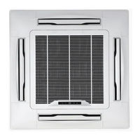
Daikin RXS35D2VMB Service Manual (381 pages)
Sky-Air Indoor
Brand: Daikin
|
Category: Air Conditioner
|
Size: 7 MB
Table of Contents
-
-
Fcq100, 125B24
-
Fcq71D26
-
Fbq35, 50B32
-
Fbq60, 71B34
-
Fbq100, 125B36
-
Fdq125B38
-
Fdq200, 250B40
-
Fhq35, 50B42
-
Fhq60, 71B44
-
Fhq100B46
-
Fhq125B48
-
Fuq71B50
-
Fuq100, 125B52
-
Faq71B54
-
Faq100B56
-
Fdeq71, 100B58
-
Fdeq125B60
-
-
-
Fbq71B90
-
Fbq100, 125B92
-
Fuq71, 100, 125B100
-
Faq71B102
-
Faq100B104
-
Fdeq71B106
-
Fdeq100B108
-
Fdeq125B110
-
-
Fcq100, 125B115
-
Fuq71, 100, 125B121
-
Faq71B122
-
Faq100B123
-
Fcq35, 50, 60B126
-
Fcq71, 100, 125B127
-
Fhq35, 50, 60B134
-
Fhq71, 100, 125B135
-
Fuq71, 100, 125B136
-
Faq71B137
-
Faq100B138
-
Restart Standby147
-
PMV Control153
-
-
Test Run Checks218
-
-
Fbq100, 125B243
-
Fbq60, 71B243
-
Fdeq125B243
-
-
Fcq100, 125B246
-
Fbq35, 50B250
-
Fbq60, 71B252
-
Fbq100, 125B254
-
Fdeq71, 100B258
-
Fdeq125B260
-
Ffq25, 50, 60B282
-
Fuq71, 100, 125B334
-
Removal of Fan338
-
Faq71B351
-
Faq100B362
Advertisement

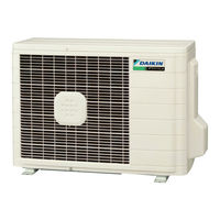
Daikin RXS35D2VMB Service Manual (228 pages)
Brand: Daikin
|
Category: Air Conditioner
|
Size: 14 MB
Table of Contents
-
-
Cooling Only17
-
Heat Pump30
-
-
-
Indoor Unit49
-
Outdoor Unit51
-
-
-
Fan Control77
-
Malfunctions82
-
Instruction88
-
ECONO Operation102
-
TIMER Operation105
-
-
Air Filter108
-
-
Troubleshooting110
-
Troubleshooting120
-
Compressor Lock131
-
DC Fan Lock132
-
Insufficient Gas150
-
Check153
-
How to Check153
-
-
Indoor Unit161
-
Outdoor Unit192
-
Part 8 Others212
-
Others213
-
Part 9 Appendix216
-
Piping Diagrams217
-
Indoor Units217
-
Outdoor Units218
-
-
Wiring Diagrams220
-
Indoor Units220
-
Outdoor Units220
-
-
Index222
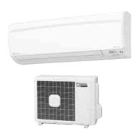
Daikin RXS35D2VMB Service Manual (205 pages)
Inverter Pair Wall Mounted Type, Cooling Only, Heat Pump
Brand: Daikin
|
Category: Air Conditioner
|
Size: 3 MB
Table of Contents
-
-
Cooling Only16
-
Heat Pump19
-
-
-
Indoor Unit26
-
Outdoor Unit28
-
-
-
Fan Control54
-
Malfunctions59
-
Instruction65
-
-
Compressor Lock108
-
DC Fan Lock109
-
Insufficient Gas127
-
Check130
-
How to Check130
-
-
Indoor Unit138
-
Outdoor Unit169
-
Part 8 Others189
-
Others190
-
Part 9 Appendix193
-
Piping Diagrams194
-
Indoor Units194
-
Outdoor Units195
-
-
Wiring Diagrams197
-
Indoor Units197
-
Outdoor Units197
-
-
Index199
Advertisement
Daikin RXS35D2VMB Service Manual (184 pages)
Inverter Pair Floor / Ceiling Suspended Dual Type B-Series
Brand: Daikin
|
Category: Air Conditioner
|
Size: 6 MB
Table of Contents
-
-
Cooling Only15
-
Heat Pump17
-
-
-
Indoor Unit21
-
Outdoor Unit23
-
-
-
Fan Control47
-
Malfunctions52
-
Instruction58
-
-
Compressor Lock100
-
DC Fan Lock101
-
Insufficient Gas119
-
Check122
-
Indoor Unit131
-
Outdoor Unit147
-
Part 8 Others168
-
Others169
-
Part 9 Appendix172
-
Piping Diagrams173
-
Indoor Units173
-
Outdoor Units174
-
-
Wiring Diagrams176
-
Indoor Units176
-
Outdoor Units176
-
-
Index178
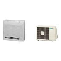
Daikin RXS35D2VMB Service Manual (184 pages)
Inverter Pair Floor Standing Type B-Series
Brand: Daikin
|
Category: Air Conditioner
|
Size: 6 MB
Table of Contents
-
-
Cooling Only15
-
Heat Pump17
-
-
-
Indoor Unit21
-
Outdoor Unit23
-
-
-
Fan Control49
-
Malfunctions54
-
Instruction60
-
-
Compressor Lock104
-
DC Fan Lock105
-
Insufficient Gas123
-
Check126
-
Indoor Unit135
-
Outdoor Unit148
-
Part 8 Others168
-
Others169
-
Part 9 Appendix172
-
Piping Diagrams173
-
Indoor Units173
-
Outdoor Units174
-
-
Wiring Diagrams176
-
Indoor Units176
-
Outdoor Units176
-
-
Index178
Advertisement