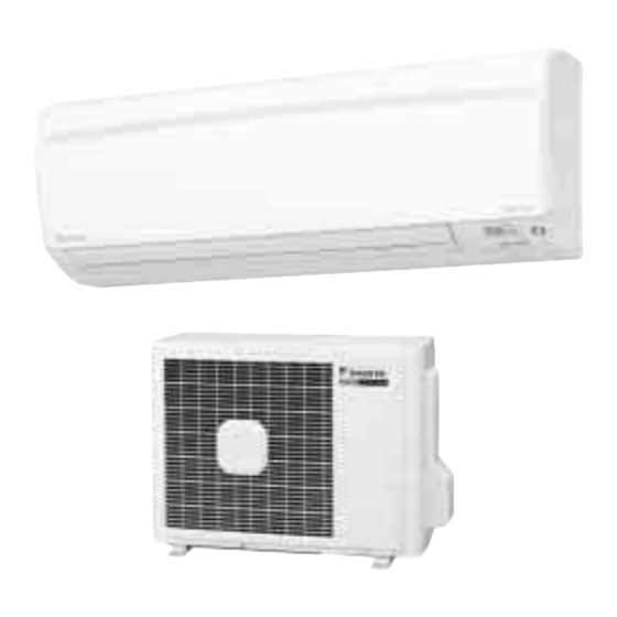
Daikin D Series Service Manual
Inverter pair wall mounted type, cooling only, heat pump
Hide thumbs
Also See for D Series:
- Service manual (479 pages) ,
- Installation manual (29 pages) ,
- Service manual (352 pages)
Table of Contents
Advertisement
Quick Links
Advertisement
Table of Contents
Troubleshooting


Need help?
Do you have a question about the D Series and is the answer not in the manual?
Questions and answers