Sign In
Upload
Manuals
Brands
Daikin Manuals
Air Conditioner
F-Series
Daikin F-Series Manuals
Manuals and User Guides for Daikin F-Series. We have
10
Daikin F-Series manuals available for free PDF download: Service Manual, Technical Manual, Instruction Manual, Installation Manual
Daikin F-Series Service Manual (355 pages)
Brand:
Daikin
| Category:
Inverter
| Size: 13 MB
Table of Contents
Table of Contents
3
Introduction
6
Safety Cautions
6
Used Icons
10
Part 1 List of Functions
12
List of Functions
13
Cooling Only Models
13
Heat Pump Models
18
Part 2 Specifications
25
Indoor Units - Cooling Only
25
Outdoor Units - Cooling Only
34
Indoor Units - Heat Pump
35
Outdoor Units - Heat Pump
46
Part 3 Printed Circuit Board Connector Wiring Diagram
48
Printed Circuit Board Connector Wiring Diagram
49
Wall Mounted Type
49
Duct Connected Type
58
Floor / Ceiling Suspended Dual Type
60
Floor Standing Type
63
Ceiling Suspended Type
65
Outdoor Units
67
Part 4 Function and Control
70
Main Functions
71
Frequency Principle
71
Power-Airflow Dual Flaps, Wide Angle Louvers and Auto-Swing
73
Operation Starting Control
75
Fan Speed Control for Indoor Units
76
Programme Dry Function
77
Automatic Operation
78
Thermostat Control
79
Night Set Mode
80
ECONO Mode
81
INTELLIGENT EYE (Wall Mounted Type Only)
82
HOME LEAVE Operation
84
Inverter POWERFUL Operation
85
Other Functions
86
Function of Main Structural Parts
88
Main Structural Parts
88
Function of Thermistor
89
Control Specification
93
Mode Hierarchy
93
Frequency Control
94
Controls at Mode Changing / Start-Up
97
Discharge Pipe Control
99
Input Current Control
99
Freeze-Up Protection Control
100
Heating Peak-Cut Control
100
Fan Control
101
Liquid Compression Protection Function 2
101
Defrost Control
102
Electronic Expansion Valve Control
103
Malfunctions
107
Forced Operation Mode
108
Wiring-Error Check
109
Additional Function
111
Part 5 Operation Manual
114
System Configuration
115
Operation Instructions
115
Instruction
116
FTK(X)S, FTXG, CTXG, FDK(X)S, FLK(X)S Series
116
FVXS Series
192
FHQ Series
223
Operation Range
226
Part 6 Service Diagnosis
236
Caution for Diagnosis
237
Troubleshooting with Operation Lamp
237
Problem Symptoms and Measures
239
Service Check Function
240
Check Method 1
240
Check Method 2
242
Code Indication on the Remote Controller
244
Error Codes and Description of Fault
244
Troubleshooting
245
Indoor Units
245
Outdoor Units
246
Indoor Unit PCB Abnormality
247
Freeze-Up Protection Control or High Pressure Control
248
Fan Motor or Related Abnormality
250
Thermistor or Related Abnormality (Indoor Unit)
253
Front Panel Open / Close Fault
254
Signal Transmission Error (between Indoor and Outdoor Unit)
255
Unspecified Voltage (between Indoor and Outdoor Units)
257
Freeze-Up Protection Control
258
Outdoor Unit PCB Abnormality
260
OL Activation (Compressor Overload)
261
Compressor Lock
262
DC Fan Lock
263
Input over Current Detection
264
Discharge Pipe Temperature Control
266
High Pressure Control in Cooling
267
Compressor Sensor System Abnormality
269
Position Sensor Abnormality
271
CT or Related Abnormality
272
Thermistor or Related Abnormality (Outdoor Unit)
274
Sibe12
275
Electrical Box Temperature Rise
276
Radiation Fin Temperature Rise
278
Output over Current Detection
280
Insufficient Gas
282
Low-Voltage Detection or Over-Voltage Detection
284
Signal Transmission Error (on Outdoor Unit PCB)
285
Anti-Icing Function in Other Rooms / Unspecified Voltage
286
(Between Indoor and Outdoor Units)
286
Anti-Icing Function in Other Rooms / Unspecified Voltage (between Indoor and Outdoor Units)
286
Check
287
How to Check
287
Electronic Expansion Valve Check
288
Installation Condition Check
291
Discharge Pressure Check
292
Power Transistor Check
294
Main Circuit Electrolytic Capacitor Check
295
Part 7 Removal Procedure
298
Outdoor Unit
299
Removal of the Panels and Plates
299
Removal of the Electrical Box
303
Removal of the PCB
311
Removal of the Propeller Fan / Fan Motor
317
Removal of the Sound Blanket
319
Removal of Electronic Expansion Valve Coil, Four Way Valve Coil and Thermistor
323
Removal of the Distributor
326
Removal of the Four Way Valve
327
Removal of the Compressor
328
Part 8 Others
331
Others
331
Test Run from the Remote Controller
331
Jumper Settings
332
Part 9 Appendix
334
Piping Diagrams
335
Indoor Units
335
Outdoor Units
341
Wiring Diagrams
342
Indoor Units
342
Outdoor Units
347
Index
348
Advertisement
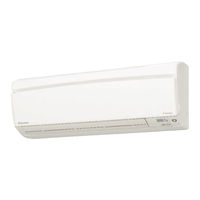
Daikin F-Series Service Manual (300 pages)
Wall Mounted Type
Brand:
Daikin
| Category:
Air Conditioner
| Size: 21 MB
Table of Contents
Table of Contents
3
Introduction
6
Safety Cautions
6
Used Icons
10
Part 1 List of Functions
12
List of Functions
13
Part 2 Specifications
18
Specifications
19
Cooling Only
19
Heat Pump
23
Part 3 Printed Circuit Board Connector Wiring Diagram
28
Printed Circuit Board Connector Wiring Diagram
29
Indoor Units
29
Display Pcb
32
Outdoor Units
33
Part 4 Function and Control
36
Main Functions
37
Frequency Principle
37
Power-Airflow Dual Flaps, Wide Angle Louvers and Auto-Swing
39
Fan Speed Control for Indoor Units
40
Programme Dry Function
41
Automatic Operation
42
Thermostat Control
43
Night Set Mode
44
ECONO Mode
45
Intelligent Eye
46
Home Leave Operation
48
Inverter Powerful Operation
49
Other Functions
50
Function of Thermistor
52
Heat Pump Model
52
Cooling Only Model
53
Control Specification
54
Mode Hierarchy
54
Frequency Control
55
Controls at Mode Changing / Start-Up
57
Discharge Pipe Temperature Control
58
Compressor Protection Function
58
Input Current Control
59
Freeze-Up Protection Control
60
Heating Peak-Cut Control
60
Fan Control
61
Liquid Compression Protection Function 2
61
Defrost Control
62
Electronic Expansion Valve Control
63
Target Discharge Pipe Temperature Control
65
Malfunctions
66
Forced Operation Mode
67
Additional Function
67
Facility Setting Switch (Cooling at Low Outdoor Temperature)
68
Part 5 Operation Manual
70
System Configuration
71
Instruction
72
Safety Precautions
72
Installation Site
73
Electrical Work
73
Ftk(X)S 50 D
74
Remote Controller
76
Preparation before Operation
77
Adjusting the Air Flow Direction
82
Powerful Operation
84
Outdoor Unit Quiet Operation
85
Econo Operation
86
Intelligent Eye Operation
87
Timer Operation
89
Care and Cleaning
91
Front Panel
91
Air Filter
92
Before a Long Idle Period
93
Trouble Shooting
94
Disposal Requirements
96
Fault Diagnosis
97
Ftk(X)S 50/60/71 F, Ft(Y) 50/60 F
98
Part 6 Service Diagnosis
124
Caution for Diagnosis
125
Problem Symptoms and Measures
126
Service Check Function
127
Troubleshooting
128
Error Codes and Description
128
Indoor Unit PCB Abnormality
129
Freeze-Up Protection Control or High Pressure Control
130
Fan Motor (DC Motor) or Related Abnormality
132
Thermistor or Related Abnormality (Indoor Unit)
134
Signal Transmission Error (between Indoor and Outdoor Unit)
135
Outdoor Unit PCB Abnormality
137
OL Activation (Compressor Overload)
138
Compressor Lock
139
DC Fan Lock
140
Input over Current Detection
141
Four Way Valve Abnormality
143
Discharge Pipe Temperature Control
145
High Pressure Control in Cooling
146
Compressor Sensor System Abnormality
148
Position Sensor Abnormality
150
CT or Related Abnormality
151
Thermistor or Related Abnormality (Outdoor Unit)
153
Electrical Box Temperature Rise
155
Radiation Fin Temperature Rise
157
Output over Current Detection
159
Insufficient Gas
161
Low-Voltage Detection or Over-Voltage Detection
163
Signal Transmission Error on Outdoor Unit PCB
164
Check
165
How to Check
165
Four Way Valve Performance Check
166
Thermistor Resistance Check
167
Installation Condition Check
168
Discharge Pressure Check
169
Outdoor Unit Fan System Check
169
Power Supply Waveforms Check
170
Inverter Units Refrigerant System Check
170
Capacitor Voltage Check
171
Power Transistor Check
171
Main Circuit Electrolytic Capacitor Check
172
Part 7 Removal Procedure
174
Indoor Unit
175
Ftk(X)S 50 D
175
Removal of Front Panel
177
Removal of Front Grille
179
Removal of Electrical Box
185
Removal of Pcb
188
Removal of Drain Pan Unit
194
Removal of Fan Motor
198
Removal of Heat Exchanger
200
Removal of Fan Rotor
203
Ftk(X)S 50/60/71 F, Ft(Y)N 50/60 F
206
Fan Motor
222
Outdoor Unit
224
Rk(X)S 50/60 F, R(Y)N 50/60 E
224
Removal of the Electrical Box
232
Removal of the Pcb
236
Removal of the Sound Blanket
239
Removal of the Four Way Valve
241
Removal of the Electronic Expansion Valve
242
Removal of the Compressor
244
Rk(X)S 71 F
247
Removal of Outer Panels
247
Removal of Sound Blanket
273
Removal of Compressor
276
Part 8 Others
278
Others
279
Test Run from the Remote Controller
279
Jumper Settings
280
Part 9 Appendix
282
Piping Diagrams
283
Indoor Units
283
Outdoor Units
285
Wiring Diagrams
287
Indoor Units
287
Outdoor Units
289
Index
294
Daikin F-Series Service Manual (316 pages)
Inverter Multi for 2 Rooms
Brand:
Daikin
| Category:
Inverter
| Size: 9 MB
Table of Contents
Table of Contents
4
Introduction
7
Safety Cautions
7
Used Icons
11
Part 1 List of Functions
12
List of Functions
13
Cooling Only
13
Heat Pump
19
Part 2 Specifications
28
Cooling Only
29
Heat Pump
42
Part 3 Printed Circuit Board Connector Wiring Diagram
62
Printed Circuit Board Connector Wiring Diagram
63
Wall Mounted Type
63
Duct Connected Type
69
Floor / Ceiling Suspended Dual Type
71
Floor Standing Type
74
Outdoor Unit
76
Part 4 Function and Control
78
Main Functions
79
Frequency Principle
79
Power-Airflow Dual Flaps, Wide Angle Louvers and Auto-Swing
81
Operation Starting Control
83
Fan Speed Control for Indoor Units
84
Programme Dry Function
85
Automatic Operation
86
Thermostat Control
87
Night Set Mode
88
ECONO Mode
89
Intelligent Eye
90
HOME LEAVE Operation
92
Inverter POWERFUL Operation
93
Other Functions
94
Function of Thermistor
96
Control Specification
99
Mode Hierarchy
99
Frequency Control
100
Controls at Mode Changing / Start-Up
103
Discharge Pipe Temperature Control
105
Input Current Control
105
Freeze-Up Protection Control
106
Heating Peak-Cut Control
106
Fan Control
107
Liquid Compression Protection Function 2
107
Defrost Control
108
Electronic Expansion Valve Control
109
Malfunctions
113
Forced Operation Mode
114
Additional Function
115
Part 5 Operation Manual
116
System Configuration
117
Operation Instructions
117
Instruction
118
FTK(X)S, ATK(X)S, F(C)(A)TXG, FLK(X)S Series
118
Installation Site
120
FVXS Series
181
Part 6 Service Diagnosis
210
Caution for Diagnosis
211
Problem Symptoms and Measures
213
Service Check Function
214
Check Method 1
214
Check Method 2
216
Troubleshooting
218
Error Codes and Description
218
Indoor Unit PCB Abnormality
219
Freeze-Up Protection Control or High Pressure Control
220
Fan Motor or Related Abnormality
222
Thermistor or Related Abnormality (Indoor Unit)
225
Front Panel Open / Close Fault
226
Freeze-Up Protection Control
227
OL Activation (Compressor Overload)
229
Compressor Lock
230
DC Fan Lock
231
Input over Current Detection
232
Discharge Pipe Temperature Control
234
High Pressure Control in Cooling
235
Compressor Sensor System Abnormality
237
Position Sensor Abnormality
238
DC Voltage / DC Current Sensor Abnormality
240
Thermistor or Related Abnormality (Outdoor Unit)
241
Electrical Box Temperature Rise
243
Radiation Fin Temperature Rise
245
Output over Current Detection
247
Insufficient Gas
249
Over-Voltage Detection / Low-Voltage Detection
251
Anti-Icing Function in Other Rooms / Unspecified Voltage (between Indoor and Outdoor Units)
252
Outdoor Unit PCB Abnormality or Signal Transmission Circuit Abnormality
253
Check
256
How to Check
256
Thermistor Resistance Check
259
Installation Condition Check
260
Discharge Pressure Check
261
Power Transistor Check
263
Main Circuit Electrolytic Capacitor Check
263
Part 7 Removal Procedure
266
Outdoor Unit
267
Removal of the Panels and Plates
267
Removal of the Electrical Box
269
Removal of the PCB
274
Removal of the Sound Blanket
279
Removal of the Propeller Fan / Fan Motor
281
Removal of the Thermistors
284
Removal of the Compressor
286
Removal of the Four Way Valve / Electronic Expansion Valve
288
Part 8 Others
290
Others
291
Test Run from the Remote Controller
291
Jumper Settings
292
Application of Silicon Grease to a Power Transistor and a Diode Bridge
294
Part 9 Appendix
296
Piping Diagrams
297
Indoor Units
297
Outdoor Units
301
Wiring Diagrams
303
Indoor Units
303
Outdoor Units
307
Index
310
Advertisement
Daikin F-Series Service Manual (280 pages)
Inverter Multi for 2 Rooms
Brand:
Daikin
| Category:
Inverter
| Size: 15 MB
Table of Contents
Table of Contents
3
Introduction
6
Safety Cautions
6
Used Icons
10
Part 1 List of Functions
12
Cooling Only
13
Heat Pump
19
Part 2 Specifications
26
Cooling Only
27
Indoor Units
27
Outdoor Units
35
Heat Pump
37
Indoor Units
37
Outdoor Units
47
Part 3 Printed Circuit Board Connector Wiring Diagram
50
Printed Circuit Board Connector Wiring Diagram
51
Wall Mounted Type
51
Duct Connected Type
57
Floor / Ceiling Suspended Dual Type
59
Floor Standing Type
62
Outdoor Unit
64
Part 4 Function and Control
66
Main Functions
67
Frequency Principle
67
Power-Airflow Dual Flaps, Wide Angle Louvers and Auto-Swing
69
Operation Starting Control
71
Fan Speed Control for Indoor Units
72
Programme Dry Function
73
Automatic Operation
74
Thermostat Control
75
Night Set Mode
76
ECONO Mode
77
Intelligent Eye
78
HOME LEAVE Operation
80
Inverter POWERFUL Operation
81
Other Functions
82
Function of Thermistor
84
Control Specification
87
Mode Hierarchy
87
Frequency Control
88
Controls at Mode Changing / Start-Up
91
Discharge Pipe Temperature Control
92
Input Current Control
92
Freeze-Up Protection Control
93
Heating Peak-Cut Control
93
Fan Control
94
Liquid Compression Protection Function 2
94
Defrost Control
95
Electronic Expansion Valve Control
96
2.12 Malfunctions
100
Forced Operation Mode
101
2.14 Additional Function
102
Part 5 Operation Manual
104
System Configuration
105
Operation Instructions
105
Instruction
106
FTK(X)S, ATK(X)S, FTXG, ATXG, FDK(X)S, FLK(X)S Series
106
Installation Site
108
FVK(X)S Series
170
Part 6 Service Diagnosis
202
Caution for Diagnosis
203
Problem Symptoms and Measures
205
Service Check Function
206
Check Method 1
206
Check Method 2
208
Troubleshooting
210
Error Codes and Description
210
Indoor Unit PCB Abnormality
211
Freeze-Up Protection Control or High Pressure Control
212
Fan Motor or Related Abnormality
214
Thermistor or Related Abnormality (Indoor Unit)
217
Front Panel Open / Close Fault
218
Freeze-Up Protection Control
219
OL Activation (Compressor Overload)
221
Compressor Lock
222
DC Fan Lock
223
Input over Current Detection
224
Discharge Pipe Temperature Control
226
High Pressure Control in Cooling
227
Compressor Sensor System Abnormality
229
Position Sensor Abnormality
230
DC Voltage / DC Current Sensor Fault
232
Thermistor or Related Abnormality (Outdoor Unit)
233
Electrical Box Temperature Rise
235
Radiation Fin Temperature Rise
237
Output over Current Detection
239
Insufficient Gas
241
Over-Voltage Detection / Low-Voltage Detection
243
Anti-Icing Function in Other Rooms / Unspecified Voltage
244
(Between Indoor and Outdoor Units)
244
Anti-Icing Function in Other Rooms / Unspecified Voltage (between Indoor and Outdoor Units)
244
Outdoor Unit PCB Abnormality or Signal Transmission Circuit Abnormality
245
Check
248
How to Check
248
Sibe12
249
Thermistor Resistance Check
251
Installation Condition Check
252
Discharge Pressure Check
253
Power Transistor Check
255
Main Circuit Electrolytic Capacitor Check
255
Part 7 Others
259
Others
259
Test Run from the Remote Controller
259
Jumper Settings
260
Part 8 Appendix
262
Piping Diagrams
263
Indoor Units
263
Outdoor Units
267
Wiring Diagrams
268
Indoor Units
268
Outdoor Units
272
Sibe12
273
Index
274
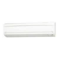
Daikin F-Series Service Manual (244 pages)
F-Series Inverter Pair Wall Mounted Type
Brand:
Daikin
| Category:
Air Conditioner
| Size: 15 MB
Table of Contents
Table of Contents
3
Introduction
6
Safety Cautions
6
Used Icons
10
Part 1 List of Functions
12
List of Functions
13
Cooling Only
13
Heat Pump
16
Part 2 Specifications
20
Specifications
21
Cooling Only
21
Heat Pump
26
Part 3 Printed Circuit Board Connector Wiring Diagram
32
Printed Circuit Board Connector Wiring Diagram
33
Indoor Units
33
Signal Receiver Pcb
34
Display Pcb
34
Outdoor Units
35
Part 4 Function and Control
38
Main Functions
39
Frequency Principle
39
Power-Airflow Dual Flaps, Wide Angle Louvers and Auto-Swing
41
Fan Speed Control for Indoor Units
42
Programme Dry Function
43
Automatic Operation
44
Thermostat Control
45
Night Set Mode
46
Intelligent Eye
47
HOME LEAVE Operation
49
Inverter POWERFUL Operation
50
Other Functions
51
Function of Thermistor
53
Heat Pump Model
53
Cooling Only Model
54
Control Specification
55
Mode Hierarchy
55
Frequency Control
56
Controls at Mode Changing / Start-Up
58
Discharge Pipe Temperature Control
59
Input Current Control
60
Freeze-Up Protection Control
61
Heating Peak-Cut Control
61
Fan Control
62
Liquid Compression Protection Function 2
62
Defrost Control
63
Electronic Expansion Valve Control
64
Target Discharge Pipe Temperature Control
66
Malfunctions
67
Forced Operation Mode
68
Additional Function
68
Part 5 Operation Manual
70
System Configuration
71
Instruction
72
Safety Precautions
72
Installation Site
73
Electrical Work
73
Names of Parts
74
Outdoor Unit
75
Remote Controller
76
Preparation before Operation
77
AUTO · DRY · COOL · HEAT · FAN Operation
80
To Change the Airflow Rate Setting
81
Adjusting the Airflow Direction
82
POWERFUL Operation
84
OUTDOOR UNIT QUIET Operation
85
HOME LEAVE Operation
86
INTELLIGENT EYE Operation
88
TIMER Operation
90
To Use on Timer Operation
91
To Combine on Timer and off Timer
91
Care and Cleaning
92
Air Filter
93
Before a Long Idle Period
94
Troubleshooting
95
Disposal Requirements
97
Part 6 Service Diagnosis
98
Caution for Diagnosis
99
Problem Symptoms and Measures
100
Service Check Function
101
Troubleshooting
104
Error Codes and Description
104
Indoor Unit PCB Abnormality
105
Freeze-Up Protection Control or High Pressure Control
106
Fan Motor (DC Motor) or Related Abnormality
108
Thermistor or Related Abnormality (Indoor Unit)
110
Signal Transmission Error (between Indoor and Outdoor Unit)
111
Outdoor Unit PCB Abnormality
113
OL Activation (Compressor Overload)
114
Compressor Lock
115
DC Fan Lock
116
Input over Current Detection
117
Four Way Valve Abnormality
119
Discharge Pipe Temperature Control
121
High Pressure Control in Cooling
122
Compressor Sensor System Abnormality
124
Position Sensor Abnormality
126
CT or Related Abnormality
127
Thermistor or Related Abnormality (Outdoor Unit)
129
Electrical Box Temperature Rise
131
Radiation Fin Temperature Rise
133
Output over Current Detection
135
Insufficient Gas
137
Low-Voltage Detection or Over-Voltage Detection
139
Signal Transmission Error on Outdoor Unit PCB
140
Check
141
How to Check
141
Four Way Valve Performance Check
142
Thermistor Resistance Check
143
Installation Condition Check
144
Discharge Pressure Check
145
Outdoor Unit Fan System Check
145
Power Supply Waveforms Check
146
Inverter Units Refrigerant System Check
146
Capacitor Voltage Check
147
Power Transistor Check
147
Main Circuit Electrolytic Capacitor Check
148
Part 7 Removal Procedure
150
Indoor Unit
151
Removal of Air Filter / Front Panel
151
Removal of Front Grille
154
Removal of Horizontal Blades / Vertical Blades
156
Removal of Electrical Box / PCB / Swing Motor
158
Removal of Heat Exchanger
164
Removal of Fan Rotor / Fan Motor
167
Outdoor Unit
169
Rks 50-71 Fvm, Rks 71 Gvmg, Rk(X)S 50/60 Fvma, Rk(X)S 50-71 Fvlt
169
Removal of the Pcb
181
Removal of the Sound Blanket
184
Removal of the Four Way Valve
186
Removal of the Electronic Expansion Valve
187
Rks 71 Fvma, Rxs 71/80/90 Fvma
192
Removal of the Electrical Box
207
Removal of Fan Motor
214
Removal of Sound Blanket
218
Removal of Compressor
221
Part 8 Others
222
Others
223
Test Run from the Remote Controller
223
Jumper Settings
224
Application of Silicon Grease to a Power Transistor and a Diode Bridge
225
Part 9 Appendix
226
Piping Diagrams
227
Indoor Units
227
Outdoor Units
228
Wiring Diagrams
232
Indoor Units
232
Outdoor Units
233
Index
238
Daikin F-Series Service Manual (206 pages)
Inverter Multi F-Series
Brand:
Daikin
| Category:
Air Conditioner
| Size: 11 MB
Table of Contents
Table of Contents
3
Introduction
6
Safety Cautions
6
Used Icons
10
Part 1 List of Functions
12
Cooling Only
13
Heat Pump
15
Part 2 Specifications
18
Cooling Only
19
Indoor Units
19
Specifications
20
Outdoor Units
21
Heat Pump
22
Indoor Units
22
Outdoor Units
24
Part 3 Printed Circuit Board Connector Wiring Diagram
26
Printed Circuit Board Connector Wiring Diagram
27
Wall Mounted Type
27
Duct Connected Type
29
Outdoor Unit
31
Part 4 Function and Control
34
Main Functions
35
Frequency Principle
35
Power-Airflow Dual Flaps, Wide-Angle Louvers and Auto-Swing
37
Fan Speed Control for Indoor Units
38
Programme Dry Function
39
Automatic Operation
40
Thermostat Control
41
Night Set Mode
42
ECONO Mode
43
Intelligent Eye
44
HOME LEAVE Operation
46
Inverter POWERFUL Operation
47
Other Functions
48
Function of Thermistor
50
Heat Pump Model
50
Cooling Only Model
52
Control Specification
53
Mode Hierarchy
53
Frequency Control
54
Controls at Mode Changing / Start-Up
57
Compressor Protection Function
58
Discharge Pipe Temperature Control
59
Input Current Control
59
Freeze-Up Protection Control
60
Heating Peak-Cut Control
60
Fan Control
61
Liquid Compression Protection Function 2
61
Defrost Control
62
Electronic Expansion Valve Control
63
Malfunctions
67
Forced Operation Mode
68
Additional Function
69
Part 5 Operation Manual
70
System Configuration
71
Operation Instructions
71
Instruction
72
Manual Contents and Reference Page
72
Safety Precautions
73
Installation Site
74
Electrical Work
74
Names of Parts
75
Remote Control
77
Preparation before Operation
81
To Set the Clock
83
AUTO·DRY·COOL·HEAT·FAN Operation
84
To Change the Air Flow Rate Setting
85
Adjusting the Air Flow Direction
86
POWERFUL Operation
88
OUTDOOR UNIT QUIET Operation
89
ECONO Operation
90
HOME LEAVE Operation
91
MOLD PROOF Operation
93
INTELLIGENT EYE Operation
94
TIMER Operation
96
To Use on Timer Operation
97
To Combine on Timer and off Timer
97
Note for Multi System
98
Priority Room Setting
99
Care and Cleaning
100
Air Filter
101
Before a Long Idle Period
102
Cleaning the Air Filter
103
Troubleshooting
107
Check Again
108
Fault Diagnosis
110
Part 6 Service Diagnosis
112
Caution for Diagnosis
113
Problem Symptoms and Measures
115
Service Check Function
116
Check Method 1
116
Check Method 2
117
Troubleshooting
119
Error Codes and Description
119
Indoor Unit PCB Abnormality
120
Freeze-Up Protection Control or High Pressure Control
121
Fan Motor or Related Abnormality
123
Ac Motor
123
DC Motor
124
Thermistor or Related Abnormality (Indoor Unit)
126
Front Panel Open / Close Fault
127
Freeze-Up Protection Control
128
OL Activation (Compressor Overload)
130
Compressor Lock
131
DC Fan Lock
132
Input over Current Detection
133
Discharge Pipe Temperature Control
135
High Pressure Control in Cooling
136
Compressor Sensor System Abnormality
138
Position Sensor Abnormality
139
DC Voltage / DC Current Sensor Abnormality
141
Thermistor or Related Abnormality (Outdoor Unit)
142
Electrical Box Temperature Rise
144
Radiation Fin Temperature Rise
146
Output over Current Detection
148
Insufficient Gas
150
Over-Voltage Detection / Low-Voltage Detection
152
Anti-Icing Function in Other Rooms / Unspecified Voltage (between Indoor and Outdoor Units)
153
Voltage (between Indoor and Outdoor Units)
153
Outdoor Unit PCB Abnormality or Signal Transmission Circuit Abnormality
154
Check
157
How to Check
157
Four Way Valve Performance Check
159
Thermistor Resistance Check
160
Installation Condition Check
161
Discharge Pressure Check
162
Power Supply Waveforms Check
162
Capacitor Voltage Check
163
Inverter Units Refrigerant System Check
163
Power Transistor Check
164
Main Circuit Electrolytic Capacitor Check
164
Hall IC Check
165
Part 7 Removal Procedure
166
Outdoor Unit
167
Removal of the Panels and Plates
167
Removal of the Electrical Box
169
Removal of the PCB
174
Removal of the Sound Blanket
179
Removal of the Propeller Fan / Fan Motor
181
Removal of the Thermistors
184
Removal of the Compressor
186
Removal of the Four Way Valve • Electronic Expansion Valve
188
Part 8 Others
190
Others
191
Test Run from the Remote Control
191
Jumper Settings
192
Application of Silicon Grease to a Power Transistor and a Diode Bridge
193
Part 9 Appendix
194
Piping Diagrams
195
Indoor Units
195
Outdoor Units
196
Wiring Diagrams
197
Indoor Units
197
Outdoor Units
198
Index
200
Drawings & Flow Charts
204
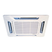
Daikin F-Series Technical Manual (51 pages)
Split Unit Air Conditioner Ceiling Cassette Cooling only 50Hz
Brand:
Daikin
| Category:
Air Conditioner
| Size: 5 MB
Table of Contents
Technical Manual
2
Table of Contents
2
Nomenclature
3
Indoor
3
Outdoor
3
Panel
4
Product Line-Up
5
Application Information
7
Operating Range
7
Refrigerant Circuit Diagrams
8
Installation Guideline
10
Sound Data
17
Sound Pressure Level
17
NC Curve
18
Engineering & Physical Data
22
Performance Data
26
Calculation Steps
26
Performance Tables
29
Outline & Dimension
38
Wiring Diagram
41
High
42
High
43
Service & Maintenance
45
Troubleshooting
47
High
49
High
50
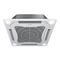
Daikin F-Series Technical Manual (44 pages)
Split Unit Air Conditioner Ceiling Cassette
Brand:
Daikin
| Category:
Air Conditioner
| Size: 3 MB
Table of Contents
Table of Contents
3
Nomenclature
5
Indoor
5
Outdoor
5
Product Line-Up
7
Application Information
9
Operating Range
9
Refrigerant Circuit Diagrams
9
Installation Guideline
11
Sound Data
16
Sound Pressure Level
16
NC Curve
17
Engineering & Physical Data
20
Performance Data
23
Calculation Steps
23
Performance Tables
25
Outline & Dimension
31
Wiring Diagram
33
Service & Maintenance
36
Troubleshooting
38
Daikin F-Series Instruction Manual (13 pages)
Chilled Water Fan Coil Unit
Brand:
Daikin
| Category:
Fan
| Size: 1 MB
Table of Contents
Outline and Dimensions
3
Safety Precautions
4
Installation of the Indoor Unit
5
Important Notice
6
Water Piping Connection
6
Electrical Wiring Connection
7
Operating Range
8
Overall Checking
8
Service and Maintenance
10
Troubleshooting
10
Daikin F-Series Installation Manual (12 pages)
Brand:
Daikin
| Category:
Fan
| Size: 1 MB
Table of Contents
Safety Precautions
3
Installation of the Indoor Unit
4
Important Notice
5
Water Piping Connection
5
Electrical Wiring Connection
6
Operating Range
7
Overall Checking
7
Service and Maintenance
9
Troubleshooting
9
Advertisement
Related Products
Daikin FCQ100PV4A
Daikin FA100FVEK
Daikin SkyAir FAQ18PVJU
Daikin FXMQ48PVJU
Daikin FXMQ80MVE
Daikin FTXS71JVMA
Daikin FDXS50F2VEB9
Daikin FXSQ63P7VEB
Daikin FXLQ20MAVE
Daikin FXHQ100AVEB
Daikin Categories
Air Conditioner
Heat Pump
Chiller
Remote Control
Air Handlers
More Daikin Manuals
Login
Sign In
OR
Sign in with Facebook
Sign in with Google
Upload manual
Upload from disk
Upload from URL