Sign In
Upload
Manuals
Brands
Control Techniques Manuals
Inverter
Commander SK
Control Techniques Commander SK Manuals
Manuals and User Guides for Control Techniques Commander SK. We have
2
Control Techniques Commander SK manuals available for free PDF download: Advanced User's Manual, Getting Started Manual
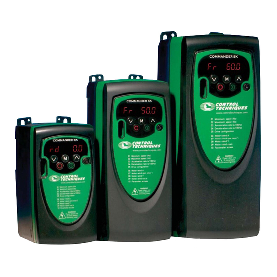
Control Techniques Commander SK Advanced User's Manual (169 pages)
AC variable speed drive for 3 phase induction motors from 0.25kW to 4kW, 0.33hp to 5hp
Brand:
Control Techniques
| Category:
Inverter
| Size: 4 MB
Table of Contents
Drive Software Version
2
Environmental Statement
2
General Information
2
Table of Contents
3
Saving Parameters
5
Loading Default Parameters
5
EUR/USA Parameter Set Differences
5
3 Parameter Description Format
6
Software Variable Maximum Term Definitions
6
Parameter Information
6
Key to Parameter Codes
7
Parameter Types
7
32 Bit Parameters
7
Drive Reset
7
Coding
8
Term Definitions
8
Sources and Destinations
8
Sample/Update Times
9
Task Routine Times
9
4 Keypad and Display
10
Selecting and Changing Parameters
10
Programming Keys
10
Control Keys
10
Status Modes
11
Speed Indications
11
Load Indications
11
5 CT Modbus RTU
12
CT Modbu RTU
12
6 User Programming (PLC Ladder Logic Programming)
13
Menu 0 Logic Diagram
18
9 Advanced Parameter Descriptions
19
Key to Parameter Coding
19
Menu Descriptions
19
Overview
19
Menu 1: Speed Reference Selection, Limits and Filters
20
Menu 1A Logic Diagram
21
Menu 1B Logic Diagram
22
Menu 1C Logic Diagram
23
Menu 1D Logic Diagram
23
Allow Negative References
25
Minimum Set Speed
25
Reference Offset Select
25
Keypad Reference
27
Precision Reference Coarse
27
Preset Selector
27
Precision Reference Fine
28
Precision Reference Update Disable
28
Percentage Trim
29
Reference in Rejection Zone
29
Power-Up Keypad Reference
30
Preset Reference Selected Indicator
30
Reference Selected Indicator
30
Menu 2: Ramps
31
Menu 2A Logic Diagram
32
Menu 2B Logic Diagram
32
Menu 2C Logic Diagram
33
Post Ramp Reference
34
Ramp Hold
34
Ramp Mode Select
34
S Ramp Acceleration Limit
35
S Ramp Enable
35
Acceleration Rate Selector
36
Standard Ramp Voltage
36
Deceleration Rate Selector
37
Jog Acceleration Rate
37
Deceleration Selected Indicator
39
Ramp Rate Units
39
Menu 3: Speed Sensing Thresholds and Frequency Input and Output
40
Menu 3A Logic Diagram
41
Menu 3B Logic Diagram
41
At Speed Window
42
Frequency Input and Output
42
Frequency Output or PWM Output Scaling
42
Zero Speed Threshold
42
Hard Frequency Reference
43
Hard Frequency Reference Selector
43
Position
43
Position Counter Reset
43
Frequency Reference
44
Frequency Reference Scaling
44
Maximum Reference Frequency
44
Position Scaling Denominator
44
Menu 4: Current Control
45
Menu 4 Logic Diagram
46
Current Magnitude (Motor Current)
48
Motor Active Current
48
Current Demand
49
Symmetrical Current Limit
49
Torque Reference
49
Current Controller Ki Gain
50
Current Controller Kp Gain
50
Torque Mode Selector
50
Thermal Protection Mode
51
Thermal Time Constant
51
Overriding Accumulator
53
Overriding Current Limit
53
Percentage Load
53
Reactive Current (Motor Magnetising Current)
53
Load Display Units
54
Low Speed Thermal Protection Mode
54
Percentage Torque
54
User Current Maximum Scaling
54
Menu 5: Machine Control
55
Menu 5 Logic Diagram
56
Motor Rpm
57
Output Frequency
57
Output Power
57
Output Voltage
57
Motor Rated Current
58
Motor Rated Frequency
58
Motor Rated Full Load Rpm
58
Motor Rated Voltage
59
Autotune
60
Motor Rated Power Factor
60
Number of Motor Poles
60
Variable Torque Select
61
Low Frequency Voltage Boost
62
Stator Resistance
62
Voltage Mode Select
62
High Stability Space Vector Modulation
63
Maximum Switching Frequency
63
Over Modulation Enable
63
Enable Slip Compensation
64
Transient Inductance
64
Voltage Offset
64
Actual Switching Frequency
65
Disable Auto-Switching Frequency Change
65
Security Unlock
65
Speed Display Units
65
Menu 6: Drive Sequencer and Clock
66
Menu 6A Logic Diagram
67
Menu 6B Logic Diagram
68
Mains Loss Mode
69
Stop Mode
69
Injection Braking Level
70
Injection Braking Time
70
Start/Stop Logic Select
70
Catch a Spinning Motor
71
Low DC Bus Operation
71
Permanently Enable Stop Key
72
Remote LED Keypad Function Key Status
72
Disable Auto-Reset on Enable
73
Drive Enable
73
Electricity Cost Per Kwh
73
Function Key Mode
73
Energy Meter: Kwh
74
Energy Meter: Mwh
74
Reset Energy Meter
74
Run Time Log: Years.days
74
Permanent Hardware Enable
75
Sequencing Bit: Jog Reverse
75
Sequencing Bit: Not Stop
75
Control Word
78
Control Word Enable
78
Enable Sequencer Latching
78
Force Cooling Fan to Run at Full Speed
79
Menu 7: Analog Inputs and Outputs
80
Menu 7 Logic Diagram
81
Analog Input 1 Mode (Terminal T2)
82
Analog Input 1 Monitor (Terminal T2)
82
Analog Input 2 Monitor (Terminal T4)
82
Heatsink Temperature
82
Analog Input 1 Destination
83
Analog Input 1 Invert
83
Analog Input 1 Scaling
83
Analog Input 2 Mode (Terminal T4)
83
Analog Input 2 Destination
84
Analog Input 2 Invert
84
DAC Output Scaling
84
DAC Output Source
84
Analog Output Control (Terminal B1)
85
Current Loop Loss Indicator
85
Drive Thermal Protection Accumulator
86
IGBT Junction Temperature
86
Menu 8: Digital Inputs and Outputs
87
Menu 8A Logic Diagram
88
Menu 8B Logic Diagram
88
Menu 8C Logic Diagram
89
Menu 8D Logic Diagram
89
Status Relay State (Terminals T5 and T6)
90
Terminal B7 Digital Input Invert
90
Digital I/O Read Word
91
Status Relay Invert
91
Status Relay Source
92
Terminal B3 Function Select
92
Terminal B7 Function Select
92
Digital Output Control (Terminal B3)
93
Menu 9: Programmable Logic, Motorised Pot and Binary Sum
94
Menu 9A Logic Diagram
95
Menu 9B Logic Diagram
96
Logic Function 1 Source 1
97
Logic Function 1 Source 1 Invert
97
Logic Function 1 Source 2
97
Motorised Pot Output
97
Logic Function 1 Delay
98
Logic Function 1 Destination
98
Logic Function 1 Output Invert
98
Logic Function 1 Source 2 Invert
98
Logic Function 2 Source 1
99
Logic Function 2 Source 1 Invert
99
Logic Function 2 Source 2
99
Logic Function 2 Source 2 Invert
99
Logic Function 2 Destination
100
Motorised Pot Bipolar Select
100
Motorised Pot Mode
100
Motorised Pot Destination
101
Motorised Pot Rate
101
Motorised Pot Scale Factor
101
Binary Sum Destination
102
Binary Sum Offset
102
Binary Sum Output
102
Menu 10: Status Logic and Diagnostic Information
104
Drive Active
105
Drive Healthy
105
Running at or below Minimum Speed
105
Zero Speed
105
Brake Resistor Alarm
106
Drive Output Is at Current Limit
106
Dynamic Brake Active
106
Regenerating
106
Drive Temperature Alarm
107
General Drive Alarm
107
Overload Alarm
107
Trip Indications
108
HF Trips
109
Under Voltage Trip and Restart Levels
109
Alarm Warnings
110
Full Power Braking Period
110
Full Power Braking Time
110
Auto-Reset Delay
111
External Trip
111
No. of Auto-Reset Attempts
111
Action on Trip Detection
112
Braking Energy Overload Accumulator
112
Hold ‘Drive Healthy’ until Last Attempt
112
User Trip
112
Status Word
113
Menu 11: General Drive Set-Up
114
Parameter Displayed at Power-Up
115
Parameter Scaling
115
Serial Address
115
Baud Rate
116
Drive Configuration
116
Modbus RTU / User Serial Mode
116
Silent Period Extension
116
Key to Switches
117
Pr 11.27 = AI.AV
117
Pr 11.27 = Ai.pr
118
Pr 11.27 = Av.pr
118
Pr 11.27 = Pad
119
Pr 11.27 = Pr
119
Pr 11.27 = E.pot
120
Pr 11.27 = Tor
120
PID Logic Diagram
121
Pr 11.27 = Pid
121
Maximum Heavy Duty Drive Current Rating
122
Pr 11.27 = HUAC
122
Software Version
122
User Security Code
122
DSP Software Version
123
Software Sub-Version
123
Status Mode Timeout
123
Voltage Rating
123
Load Defaults
124
Security Status
124
Defaults Previously Loaded
125
Select Motor 2 Parameters
125
Drive User Program Enable
126
Drive User Program Status
126
User Program Maximum Scan Time
126
Menu 12: Programmable Threshold and Variable Selector
127
Menu 12A Logic Diagram
128
Menu 12B Logic Diagram
128
Menu 12C Logic Diagram
129
Menu 12D Logic Diagram
129
Threshold Detector 1 Hysteresis
130
Threshold Detector 1 Level
130
Threshold Detector 1 Output Invert
130
Threshold Detector 1 Source
130
Variable Selector 1 Destination
131
Variable Selector 1 Mode
131
Variable Selector 1 Output
131
Threshold Detector 2 Source
132
Variable Selector 1 Control
132
Variable Selector 1 Source 1 Scaling
132
Variable Selector 1 Source 2 Scaling
132
Threshold Detector 2 Destination
133
Threshold Detector 2 Output Invert
133
Variable Selector 2 Mode
133
Variable Selector 2 Destination
134
Variable Selector 2 Output
134
Variable Selector 2 Source 1 Scaling
134
Variable Selector 2 Source 2 Scaling
134
Brake Control Function
135
Brake Release Indicator
135
Brake Function Diagram
136
Brake Sequence
136
Brake Apply Current Threshold
137
Brake Apply Frequency
137
Brake Release Current Threshold
137
Brake Release Frequency
137
Post-Brake Release Delay
138
Menu 14: PID Controller
139
Menu 14 Logic Diagram
140
PID Output
141
PID Reference Slew Rate Limit
141
Optional PID Enable Source
142
PID Enable
142
PID Integral Gain
142
PID Proportional Gain
142
Hold Integrator
143
PID Low Limit
143
PID Output Destination
143
PID Scaling
143
PID Error
144
PID Feedback
144
PID Reference
144
Menu 15: I/O Option Parameters
145
Menu 15A Logic Diagram
146
Menu 15B Logic Diagram
147
Menu 15C Logic Diagram
147
Menu 15D Logic Diagram
148
Encoder Input
149
Relay State (Terminals T21 and T23)
149
Sample Time/Update Rate
149
Real Time Clock Day Light Saving Mode
150
Relay Invert
150
Drive Encoder Lines Per Revolution
151
Drive Encoder Speed Feedback
151
Real Time Clock Update Mode
151
Terminal T21/T23 Relay Source
151
Drive Encoder Position
152
Drive Encoder Revolution Counter
152
Real Time Clock Days/Hours
152
Real Time Clock Minutes/Seconds
152
Analog Input 1 Scaling (Terminal T2)
153
Analog Output 1 Mode (Terminal T3)
153
Analog Input 1 Destination (Terminal T2)
154
Analog Input 1 Invert (Terminal T2)
154
Drive Encoder Reference Scaling
154
Maximum Drive Encoder Reference
154
Analog Output 1 Scaling (Terminal T3)
155
Analog Output 1 Source (Terminal T3)
155
Menu 18: Application Menu 1
156
Application Menu 1 Power-Down Saved Integer
157
Application Menu 1 Read-Only Integer
157
Application Menu 1 Read-Write Bit
157
Application Menu 1 Read-Write Integer
157
Application Menu 2 Read-Write Long Integer
158
Menu 20: Application Menu 2
158
Menu 21: Second Motor Map
159
Motor 2 Maximum Set Speed
160
Motor 2 Minimum Set Speed
160
Motor 2 Reference Selector
160
Motor 2 Acceleration Rate
161
Motor 2 Deceleration Rate
161
Motor 2 Motor Rated Frequency
161
Motor 2 Motor Rated Current
162
Motor 2 Motor Rated Full Load Rpm
162
Motor 2 Motor Rated Voltage
162
Fixed Boost Mode: Fd
163
Motor 2 Motor Rated Power Factor
163
Square Law Mode: Sre
163
Motor 2 Number of Motor Poles
164
Motor 2 Stator Resistance
164
Motor 2 Transient Inductance
164
Motor 2 Voltage Offset
164
Motor 2 Active
165
Motor 2 Symmetrical Current Limit
165
Motor 2 Thermal Time Constant
165
Advertisement
Control Techniques Commander SK Getting Started Manual (46 pages)
AC variable speed drive for 3 phase induction motors from 0.25kW to 4kW, 0.33hp to 5hp
Brand:
Control Techniques
| Category:
DC Drives
| Size: 1 MB
Table of Contents
Table of Contents
3
Safety Information
4
Warnings, Cautions and Notes
4
Electrical Safety - General Warning
4
System Design and Safety of Personnel
4
Environmental Limits
4
Compliance and Regulations
5
Motor
5
Adjusting Parameters
5
Electrical Installation
5
Rating Data
7
Mechanical Installation
8
Electrical Installation
10
Power Terminal Connections
10
Ground Leakage
11
Internal EMC Filter
12
I/O Specification
13
Keypad and Display
15
Programming Keys
15
Control Keys
15
Selecting and Changing Parameters
16
Saving Parameters
17
Parameter Access
17
Security Codes
18
Parameters
20
Parameter Descriptions - Level 1
20
Parameter Descriptions - Level 2
25
Parameter Descriptions - Level 3
33
Diagnostic Parameters
34
Quick Start Commissioning
35
Terminal Control
35
Keypad Control
37
Diagnostics and Protective Features
39
Options
41
Smartstick: Parameter Cloning Module
42
Documentation
42
Parameter List
43
UL Listing Information
45
Advertisement
Related Products
Control Techniques Commander SE Series
Control Techniques COMMANDER SE
Control Techniques Commander SK Series
Control Techniques Commander SE SE11200025
Control Techniques Commander SE SE11200037
Control Techniques Commander SE SE11200055
Control Techniques Commander SE SE11200075
Control Techniques Commander SE SE23200400
Control Techniques Commander SE SE23400075
Control Techniques Commander SE SE23400110
Control Techniques Categories
Control Unit
DC Drives
Controller
Inverter
Servo Drives
More Control Techniques Manuals
Login
Sign In
OR
Sign in with Facebook
Sign in with Google
Upload manual
Upload from disk
Upload from URL