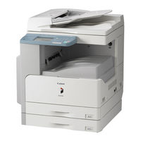
Sign In
Upload
Manuals
Brands
Canon Manuals
Printer
iR2022N
Canon iR2022N Manuals
Manuals and User Guides for Canon iR2022N. We have
2
Canon iR2022N manuals available for free PDF download: Service Manual
Canon iR2022N Service Manual (418 pages)
iR2030/2025/2022/2018 Series
Brand:
Canon
| Category:
Printer
| Size: 13.97 MB
Table of Contents
1
Service Manual
4
Symbols Used
7
Table of Contents
21
Chapter 1 Introduction
23
System Construction ..................................................................................................................................1
24
Printing Speed (Ir2025/Ir2025I) ........................................................................................................................................... 1
25
System Construction
25
Pickup/Delivery/Original Handling Accessories System Configuration (Ir2018)
26
Pickup/Delivery/Original Handling Accessories System Configuration (Ir2018I)
27
Pickup/ Delivery /Original Handling Accessories System Configuration (Ir2022/Ir2022N/Ir2025/Ir2030)
28
Pickup/Delivery/Original Handling Accessories System Configuration (Ir2022I/Ir2022K/Ir2025I/Ir2030I)
29
Reader Heater/Cassette Heater System Configuration (Ir2018/Ir2022/Ir2022N)
30
Reader Heater/Cassette Heater System Configuration (Ir2018I)
31
Reader Heater/Cassette Heater System Configuration (Ir2022K/Ir2022I/Ir2025/Ir2025I/Ir2030/Ir2030I)
32
Printing/Transmitting Accessories System Configuration (Ir2018/Ir2022/Ir2022N)
33
Printing/Transmitting Accessories System Configuration (Ir2018I/Ir2022I/Ir2022K/Ir2025/Ir2025I/Ir2030/Ir2030I)
34
Functions of the Printing/Transmission Functions (Ir2018/Ir2022/Ir2022N)
34
Functions of the Printing/Transmission Functions (Ir2018I/Ir2022I/Ir2022K/Ir2025/Ir2025I/Ir2030/Ir2030I)
34
Product Specifications
34
Names of Parts
34
External View (Ir2030I/Ir2025I/Ir2022I)
35
External View (Ir2020/Ir2020N/Ir2030/Ir2025)
35
External View (Ir2018I)
36
External View (Ir2018)
36
Cross-Section
37
Using the Machine
37
Turning On the Power Switch (Ir2018/Ir2022/Ir2022N)
38
Turning On the Power Switch (Ir2018I/Ir2020I/Ir2020K/Ir2025/Ir2025I/Ir2030/Ir2030I)
39
When Turning Off the Main Power Switch (Ir2018/Ir2022/Ir2022N)
41
When Turning Off the Main Power Switch (Ir2018I/Ir2022I/Ir2022K/Ir2025/Ir2025I/Ir2030/Ir2030I)
42
Control Panel
42
User Mode Items
42
Common Settings (Ir2030I/Ir2030/Ir2025I/Ir2025/Ir2022I/Ir2018I)
43
Timer Settings (Ir2030I/Ir2030/Ir2025I/Ir2025/Ir2022I/Ir2018I)
43
Adjustment/Cleaning (Ir2030I/Ir2030/Ir2025I/Ir2025/Ir2022I/Ir2018I)
43
Report Settings (Ir2030I/Ir2030/Ir2025I/Ir2025/Ir2022I/Ir2018I)
44
System Settings (Ir2030I/Ir2030/Ir2025I/Ir2025/Ir2022I/Ir2018I)
45
Copy Settings (Ir2030I/Ir2030/Ir2025I/Ir2025/Ir2022I/Ir2018I)
45
Communication Settings (Ir2030I/Ir2030/Ir2025I/Ir2025/Ir2022I/Ir2018I)
46
Printer Settings (Ir2030I/Ir2030/Ir2025I/Ir2025/Ir2022I/Ir2018I)
47
Address Book Settings (Ir2030I/Ir2030/Ir2025I/Ir2025/Ir2022I/Ir2018I)
47
Recommended Setting of System Management Information
47
The Reference Information of the Department ID Management
47
Maintenance By the User
47
User Maintenance Items
48
Cleaning (LCD Type)
49
Cleaning (Touch Panel Type)
50
Safety
50
Safety of the Laser Light
50
CDRH Regulations
51
Handling the Laser Unit
52
Safety of Toner
52
Point to Note about Fire
52
Cautions As to the Replacement and Disposal of Lithium Battery
53
Product Specifications
54
Function List
54
Printing Speed (Ir2030/Ir2030I)
56
Printing Speed (Ir2025/Ir2025I)
59
Printing Speed (Ir2022/Ir2022I/Ir2022K/Ir2022N))
63
Printing Speed (Ir2018/Ir2018I/Ir2018N)
67
Types of Paper
69
Chapter 2 Installation
71
Before Starting the Work (230V CENV)...................................................................................................................2
73
Making Pre-Checks
73
Selecting the Site of Installation
76
Before Starting the Work (230V CENV)
78
Unpacking and Installation
78
Unpacking and Removing the Packaging Materials
78
Installing the Drum Unit
80
Installing the Toner Bottle
82
Setting the Cassettes
83
Attaching the Ferrite Core
83
Checking the Image Quality
83
Setting the Country/Region
84
Setting the Date and Time
86
Attaching Other Parts
87
Checking the Connection to the Network
87
Checking the Network Connection
88
Checking the Network Connection
89
Flow of Accessory Installation
89
Flow of Accessary Installation (230V CENV)
90
Flow of Accessary Installation (230V CENV)
91
Installing the Card Reader
91
Points to Note
91
Checking the Contents
93
Installation Procedure
98
Registering the Card Ids
101
Installing the Heater PCB
101
Preparing the Parts
101
Preparing the Host Machine
104
Installing the Heater PCB
107
Installing the Reader Heater
107
Preparing the Parts
108
Installing the Reader Heater Harness
113
Removing Reader Components
113
Removing Parts at the Left of the Reader
115
Installing the Reader Heater
119
Installing the Cassette Heater
119
Preparing the Parts
120
Installing the Cassette Heater
123
Installing the Control Card Cable
123
Preparing the Parts
124
Installing the Control Card Cable
127
Chapter 3 Main Controller
129
Construction ...............................................................................................................................................3
131
Construction and Mechanisms
131
Construction of the Electrical Circuitry
131
Image Processor PCB
132
Image Processing
132
Overview of the Image Flow
133
Construction of the Image Processing Module
133
Reader Unit Input Image Processing
134
Compressio/ Extesion/ Editing Block
134
Printer Unit Output Image Processing
135
Flow of Image Data
135
Flow of Image Data According to Copy Functions
135
Flow of Image Data for the SEND Function
136
Flow of Image Data for the Fax Transmission
136
Flow of Image Data for the Fax Reception Function
137
Flow of Image Data for the PDL Function
138
Parts Replacement Procedure
138
Main Controller PCB
138
Preparation for Removing the Image Processor PCB
138
Removing the Image Processor PCB
140
Procedure After Replacing the Image Processor PCB
140
Sdram
140
Preparation for Removing the SDRAM
141
Removing the SDRAM
143
Chapter 4 Original Exposure System
145
Specifications, Control Methods, and Functions (Ir2030I/Ir2030/Ir2025I/Ir2025/Ir2022I/Ir2022) ...................... 4
146
Contact Sensor HP Sensor....................................................................................................................................4
147
Construction
147
Specifications, Control Methods, and Functions (Ir2030I/Ir2030/Ir2025I/Ir2025/Ir2022I/Ir2022)
147
Specifications, Control Methods, and Functions (Ir2018I/Ir2018)
148
Major Components (Ir2030I/Ir2030/Ir2025I/Ir2025/Ir2022I/Ir2022)
149
Major Components (Ir2018I/Ir2018)
149
Control System Configuration (Ir2030I/Ir2030/Ir2025I/Ir2025/Ir2022I/Ir2022)
150
Control System Configuration (Ir2018I/Ir2018)
151
Reader Controller PCB (Ir2030I/Ir2030/Ir2025I/Ir2025/Ir2022I/Ir2022)
151
Reader Controller PCB (Ir2018I/Ir2018)
152
Basic Sequence
152
Basic Sequence at Power-On
153
Basic Sequence After Depression of Start Key (Book Mode, One Sheet of Original)
153
Basic Sequence After Depression of Start Key (ADF Mode, One Sheet of Original)
154
Various Control
154
Controlling the Scanner Drive System
154
Outline
155
Reader Motor Control
155
Contact Image Sensor (CIS)
155
Outline
156
Analog Control Performed By the CIS (Ir2022I/Ir2022/Ir2018I/Ir2018)
157
Analog Control Performed By the CIS (Ir2030I/Ir2030/Ir2025I/Ir2025/Ir2022I/Ir2022)
157
Enlargement/Reduction
157
Magnification Change in Vertical Scan Direction
157
Magnification Change in Horizontal Scan Direction
157
Detecting the Size of Originals
157
Outline
158
Outline of Original Size Detection
160
Dirt Sensor Control
160
Outline
161
Image Processing
161
Outline
162
CMOS Sensor Drive
162
CMOS Sensor Output Gain Correction and Offset Correction
162
CMOS Sensor Output A/D Conversion
162
Shading Correction (Outline)
163
Shading Adjustment
163
Shading Correction
164
Parts Replacement Procedure
164
Copyboard Glass
164
Removing the Copyboard Glass
164
Procedure After Replacing the Copyboard Glass (Model Equipped with ADF)
164
Removing the ADF Reading Glass
164
Reader Controller PCB
165
Reader Controller PCB
166
Scanner Motor
166
Removing the Scanner Motor
166
Contact Sensor
166
Removing the Contact Image Sensor (CIS)
166
Procedure After Replacing the Cis(Touch Panel Type)
166
Copyboard Cover Open/Close Sensor
167
Original Size Sensor
167
Contact Sensor Hp Sensor
167
Removing the Original Sensor (Vertical Scan Direction)
168
Removing the Original Sensor (Horizontal Scan Direction)
168
Reader Heater (Option)
168
Removing the Reader Heater (Right)
168
Removing the Reader Heater (Left)
171
Chapter 5 Laser Exposure
173
Overview ..................................................................................................................................................................5
175
Construction
175
Specifications and Control Mechanism
175
Main Components
176
Control System Configuration
176
Various Controls
176
Controlling the Laser Activation Timing
176
Laser Emission ON/OFF Control
177
Horizontal Synchronization Control
177
Controlling the Intensity of Laser Light
177
Automatic Photocurrent Control (APC)
177
Controlling the Laser Scanner Motor
177
Laser Scanner Motor Control
178
Controlling the Laser Shutter
178
Laser Shutter Control
180
Parts Replacement Procedure
180
Laser Scanner Unit
180
Removing the Laser Scanner Unit
181
Chapter 6 Image Formation
183
Major Components of Image Formation System .....................................................................................................6
185
Construction
185
Specifications of Image Formation System
185
Major Components of Image Formation System
187
Image Formation Process
187
Basic Sequence
187
Basic Sequence of Operation
189
Driving and Controlling the High-Voltage System
189
Outline
189
Drum Unit
189
Outline of the Drum Unit
190
Charging Mechanism
190
Primary Charging Bias Control
190
Developing Unit
190
Outline
190
Developing Bias Control
191
Toner Container
191
Outline
191
Transfer Unit
191
Outline of the Transfer Unit
192
Controlling the Transfer Bias
192
Transfer Roller Bias Control
192
Separation Mechanism
192
Static Eliminator Bias Control
193
Photosensitive Drum Cleaning
193
Outline
193
Waste Toner Full Detection
194
Parts Replacement Procedure
194
Drum Unit
194
Removing the Drum Unit
194
Developing Assembly
194
Removing the Developing Assembly
194
Precautions about Installation of Developing Assembly
195
Transfer Charging Roller
195
Removing the Transfer Charging Roller
197
Chapter 7 Pickup/Feeding System
199
Specifications/Configuration/Operation Methods .................................................................................................... 7
200
Registration Clutch...............................................................................................................................................7
201
Construction
201
Specifications/Configuration/Operation Methods
202
Locations of Main Units
202
Roller Layout Drawing
203
Paper Path Drawing (Printer On Its Own)
203
Paper Path Drawing (Finisher-U2)
204
Paper Path Drawing (Duplex Unit-B1/Finisher-U2)
204
Paper Path Drawing (Duplex Unit-B1)
204
Paper Path Drawing (Duplex-B1/Inner 2Way Tray-E2)
205
Paper Path Drawing(Inner 2Way Tray-E2)
205
Sensor Layout Drawing
206
Detecting Jams
206
Delay Jams
206
Delay Jam in Pickup Assembly
206
Delay Jam in Delivery Assembly (Paper Leading Edge Jam at First Delivery Sensor/Wound Paper Jam at Fixing Assembly)
207
Stationary Jams
207
Stationary Jam in Pickup Assembly
207
Stationary Jam in Delivery Assembly
207
Delivery Sensor)
207
Other Jams
207
Door Open Jam
208
Cassette Pickup Operation
209
Cassette Paper Size Detection
210
Manual Feed Pickup Unit
210
Overview
210
Post-Pickup Control After Multi Manual Feed Pickup
211
Parts Replacement Procedure
211
Pickup Roller
211
Removing the Cassette Paper Pickup Roller
211
Cassette
211
Removing the Cassette Unit
212
Cassette Pickup Assembly
212
Removing the Cassette Pickup Assembly
212
Cassette Size Sensor
212
Removing the Paper Size Detection Switches
212
Cassette Retry Paper Sensor
212
Removing the Retry Sensor
213
Cassette Paper Sensor
213
Removing the Cassette Paper Presence/Absence Sensor
213
Cassette Pickup Solenoid
213
Removing the Cassette Pickup Solenoid
213
Manual Pickup Roller
213
Removing the Multifeeder Pickup Roller
214
Manual Feed Tray Paper Sensor
214
Removing the Multifeeder Paper Presence/Absence Sensor
214
Manual Feed Pickup Solenoid
214
Removing the Multifeeder Pickup Solenoid
215
Registration Roller
215
Removing the Registration Roller
215
Removing the Registration Clutch
216
Separation Roller
216
Removing the Feed and Separation Rollers
216
Separation Pad
216
Removing the Separation Pad
217
Chapter 8 Fixing System
219
Specifications, Control Mechanisms and Functions ................................................................................................8
221
Construction
221
Specifications, Control Mechanisms and Functions
221
Major Components
222
Various Control Mechanisms
222
Controlling the Speed of the Fixing Film
222
Controlling the Fixing Film Speed
222
Controlling the Fixing Film Temperature
222
Outline
223
Controlling the Fixing Film Temperature
223
Target Temperatures By Mode (Ir2030/Ir2030I)
223
Target Temperatures By Mode (Ir2025/Ir2025I)
224
Target Temperatures By Mode (Ir2022/Ir2022I/Ir2022K/Ir2022N)
225
Target Temperatures By Mode (Ir2018/Ir2018I/Ir2018N)
225
Detecting the Passage of Paper
225
Protective Functions
228
Parts Replacement Procedure
228
Fixing Unit
228
Removing the Fixing Unit
229
Pressure Roller
229
Removing the Pressure Roller
229
Fixing Film
229
Removing the Fixing Film Unit
232
Fixing Delivery Sensor
232
Removing the Fixing Delivery Sensor
233
Fixing Film Sensor
233
Removing the Fixing Film Sensor
235
Chapter 9 External and Controls
237
Overview (Ir2022/Ir2022N/Ir2018/Ir2018N) ........................................................................................................ 9
239
Control Panel
239
Overview (Ir2030I/Ir2030/Ir2025I/Ir2025/Ir2022K/Ir2022I/Ir2018I)
240
Overview (Ir2022/Ir2022N/Ir2018/Ir2018N)
240
Overview (Ir2030I/Ir2030/Ir2025I/Ir2025/Ir2022K/Ir2022I/Ir2018I)
240
Fan Control
241
Power Supply System
241
Power Supply
241
Outline
242
Rated Output of the Power Supply PCB
242
Protection Function
242
Protective Mechanisms
243
Parts Replacement Procedure
243
External Covers
243
Delivery Tray
243
Right Cover (Lower)
243
Right Cover (Upper)
243
Rear Cover
244
Reader
244
Reader Rear Cover
244
Main Drive Assembly
244
Removing the Main Drive Unit
246
Fixing Drive Assembly
246
Removing the Fixing Drive Unit
246
Power Supply Unit
246
Removing the Main Power Supply PCB
247
Control Panel
247
Removing the Operation Panel Unit (LCD Type)
247
Removing the Operation Panel Unit (Touch Panel Type)
248
DC Controller PCB
248
Removing the DC Controller PCB
248
Option Power Supply PCB
248
Removing the Option Power Supply PCB
248
Hvt Pcb
248
Removing the HVT PCB
249
Removing the Fixing Heat Discharge Fan (With Duplex Unit Type)
250
Fan Filter
250
Removing the Fan Filter (Non Duplex Unit)
251
Removing the Fan Filter (With Duplex Unit Type)
252
Motor of Main Drive Assembly
252
Removing the Main Motor
252
Fixing Driver Motor
252
Removing the Fixing Unit Drive Motor
252
Left Door
252
Removing the Left Door (Non Duplex Unit Type)
253
Removing the Left Door (With Duplex Unit Type)
255
Chapter 10 RDS
255
Rds
259
Overview
259
Application Operation Mode
259
Communication Test
259
Communication Log
259
Detail of Communication Log
259
Initialization of E-Rds
260
SOAP Communication Function
261
Retransmission at the Time of SOAP Transmission Error
261
E-Rds Setting Screen
262
Report Output of Communication Error Log
262
Sleep Operation
263
Alarm Filtering, Alert Filtering
263
CA Certificate
263
Settings of Network Connection (Installation/Maintenance)
263
Settings of E-Rds (Installation/Maintenance)
264
Troubleshooting
264
Error Message List
269
Chapter 11 Maintenance and Inspection
273
Periodically Replaced Parts
273
Overview
273
Reader Unit
273
Printer Unit
273
Durables and Consumables
274
Scheduled Servicing Basic Procedure
274
Scheduled Servicing
275
Chapter 12 Standards and Adjustments
279
Scanning System
279
Procedure After Replacing the CIS (LCD Type)
279
Procedure After Replacing the CIS (Touch Panel Type)
279
Procedure After Replacing the Copyboard Glass (With ADF)
279
Image Formation System
279
Procedure After Replacing the Developing Assembly
280
Procedure After Replacing the USB Memory (Touch Panel Type)
280
Actions to Take before All Clearing (Backing Up the User Data)
283
Chapter 13 Correcting Faulty Images
285
Fans............................................................................................................................................................9
287
Making Lnitial Checks
287
Site Environment
287
Checking the Paper
287
Checking the Placement of Paper
287
Checking the Durables
287
Checking the Units and Functional Systems
288
Others
288
Outline of Electrical Components
288
Clutch/Solenoid
288
List of Clutches/Solenoids
289
Motor
289
List of Motors
290
Fan
290
List of Fans
291
Sensor
291
List of Sensors
294
Switch
294
List of Switches
295
Lamps, Heaters, and Others
295
List of Lamps, Heaters, and Others
297
Pcbs
297
List of Pcbs
301
Chapter 14 Self Diagnosis
305
Error Code Table
305
List of Error Codes
306
Error Code Details
309
Jam Code
309
Jam Codes (Related to Printer Unit)
309
Jam Codes (Related to Finisher)
309
Jam Codes (Related to ADF)
309
Jam Codes (Related to Duplex Unit)
310
Jam Codes (Related to Inner 2-Way Tray)
311
Finisher Error Codes
311
Error Code Details
314
FAX Error Codes
314
Outline
314
Error Code Outline
314
User Error Code
314
Service Error Code
Advertisement
Canon iR2022N Service Manual (348 pages)
iR2030/2025/2022/2018 Series
Brand:
Canon
| Category:
Printer
| Size: 16.87 MB
Table of Contents
1
Service Manual
4
Symbols Used
7
Table of Contents
19
Chapter 1 Introduction
23
System Construction
23
Pickup/ Delivery /Original Handling Accessories System Configuration (Ir2022/Ir2022N/Ir2025/Ir2030)
24
Pickup/Delivery/Original Handling Accessories System Configuration (Ir2022I/Ir2022K/Ir2025I/Ir2030I)
25
Reader Heater/Cassette Heater System Configuration (Ir2022K/Ir2022I/Ir2025/Ir2025I/Ir2030/Ir2030I)
26
Printing/Transmitting Accessories System Configuration (Ir2018I/Ir2022I/Ir2022K/Ir2025/Ir2025I/Ir2030/Ir2030I)
27
Functions of the Printing/Transmission Functions (Ir2018I/Ir2022I/Ir2022K/Ir2025/Ir2025I/Ir2030/Ir2030I)
27
Product Specifications
27
Names of Parts
27
External View (Ir2020/Ir2020N/Ir2030/Ir2025)
28
Cross-Section
29
Using the Machine
29
Turning On the Power Switch (Ir2018I/Ir2020I/Ir2020K/Ir2025/Ir2025I/Ir2030/Ir2030I)
30
When Turning Off the Main Power Switch (Ir2018I/Ir2022I/Ir2022K/Ir2025/Ir2025I/Ir2030/Ir2030I)
31
Control Panel
31
User Mode Items
31
Common Settings (Ir2030I/Ir2030/Ir2025I/Ir2025/Ir2022I/Ir2018I)
32
Timer Settings (Ir2030I/Ir2030/Ir2025I/Ir2025/Ir2022I/Ir2018I)
32
Adjustment/Cleaning (Ir2030I/Ir2030/Ir2025I/Ir2025/Ir2022I/Ir2018I)
32
Report Settings (Ir2030I/Ir2030/Ir2025I/Ir2025/Ir2022I/Ir2018I)
33
System Settings (Ir2030I/Ir2030/Ir2025I/Ir2025/Ir2022I/Ir2018I)
34
Copy Settings (Ir2030I/Ir2030/Ir2025I/Ir2025/Ir2022I/Ir2018I)
34
Communication Settings (Ir2030I/Ir2030/Ir2025I/Ir2025/Ir2022I/Ir2018I)
35
Printer Settings (Ir2030I/Ir2030/Ir2025I/Ir2025/Ir2022I/Ir2018I)
35
Address Book Settings (Ir2030I/Ir2030/Ir2025I/Ir2025/Ir2022I/Ir2018I)
36
Recommended Setting of System Management Information
36
The Reference Information of the Department ID Management
36
Maintenance By the User
36
User Maintenance Items
36
Cleaning (Touch Panel Type)
37
Safety
37
Safety of the Laser Light
38
CDRH Regulations
38
Handling the Laser Unit
38
Safety of Toner
39
Point to Note about Fire
39
Cautions As to the Replacement and Disposal of Lithium Battery
40
Product Specifications
42
Function List
42
Printing Speed (Ir2030/Ir2030I)
45
Types of Paper
47
Chapter 2 Installation
51
Making Pre-Checks
51
Selecting the Site of Installation
51
Before Starting the Work (230V CLA_CHK_CSPL)
53
Unpacking and Installation
53
Unpacking and Removing the Packaging Materials
53
Installing the Drum Unit
54
Installing the Toner Bottle
55
Setting the Cassettes
56
Attaching the Ferrite Core
57
Checking the Image Quality
57
Setting the Country/Region
57
Setting the Date and Time
58
Checking the Connection to the Network
58
Checking the Network Connection
59
Flow of Accessory Installation
59
Flow of Accessary Installation (230V CLA/CHK/CSPL)
60
Installing the Card Reader
60
Points to Note
60
Checking the Contents
61
Installation Procedure
63
Registering the Card Ids
65
Installing the Heater PCB
65
Preparing the Parts
65
Preparing the Host Machine
66
Installing the Heater PCB
68
Installing the Reader Heater
68
Preparing the Parts
69
Installing the Reader Heater Harness
72
Removing Reader Components
72
Removing Parts at the Left of the Reader
73
Installing the Reader Heater
75
Installing the Cassette Heater
75
Preparing the Parts
76
Installing the Cassette Heater
78
Installing the Control Card Cable
78
Preparing the Parts
79
Installing the Control Card Cable
81
Chapter 3 Main Controller
85
Construction
85
Construction and Mechanisms
85
Construction of the Electrical Circuitry
85
Image Processor PCB
86
Image Processing
86
Overview of the Image Flow
87
Construction of the Image Processing Module
87
Reader Unit Input Image Processing
88
Compressio/ Extesion/ Editing Block
88
Printer Unit Output Image Processing
89
Flow of Image Data
89
Flow of Image Data According to Copy Functions
89
Flow of Image Data for the SEND Function
90
Flow of Image Data for the Fax Transmission
90
Flow of Image Data for the Fax Reception Function
91
Flow of Image Data for the PDL Function
92
Parts Replacement Procedure
92
Main Controller PCB
92
Preparation for Removing the Image Processor PCB
92
Removing the Image Processor PCB
94
Procedure After Replacing the Image Processor PCB
94
Sdram
94
Preparation for Removing the SDRAM
95
Removing the SDRAM
97
Chapter 4 Original Exposure System
101
Construction
101
Specifications, Control Methods, and Functions (Ir2030I/Ir2030/Ir2025I/Ir2025/Ir2022I/Ir2022N/Ir2022)
101
Major Components (Ir2030I/Ir2030/Ir2025I/Ir2025/Ir2022I/Ir2022N/Ir2022)
102
Control System Configuration (Ir2030I/Ir2030/Ir2025I/Ir2025/Ir2022I/Ir2022N/Ir2022)
103
Reader Controller PCB (Ir2030I/Ir2030/Ir2025I/Ir2025/Ir2022I/Ir2022N/Ir2022)
104
Basic Sequence
104
Basic Sequence at Power-On
105
Basic Sequence After Depression of Start Key (Book Mode, One Sheet of Original)
105
Basic Sequence After Depression of Start Key (ADF Mode, One Sheet of Original)
106
Various Control
106
Controlling the Scanner Drive System
106
Outline
106
Reader Motor Control
107
Contact Image Sensor (CIS)
107
Outline
108
Analog Control Performed By the CIS (Ir2030I/Ir2030/Ir2025I/Ir2025/Ir2022I/Ir2022K/Ir2018I)
109
Enlargement/Reduction
109
Magnification Change in Vertical Scan Direction
109
Magnification Change in Horizontal Scan Direction
109
Detecting the Size of Originals
109
Outline
109
Outline of Original Size Detection
111
Dirt Sensor Control
111
Outline
113
Image Processing
113
Outline
114
CMOS Sensor Drive
114
CMOS Sensor Output Gain Correction and Offset Correction
114
CMOS Sensor Output A/D Conversion
114
Shading Correction (Outline)
115
Shading Adjustment
115
Shading Correction
116
Parts Replacement Procedure
116
Copyboard Glass
116
Removing the Copyboard Glass
116
Procedure After Replacing the Copyboard Glass (Model Equipped with ADF)
116
Removing the ADF Reading Glass
116
Reader Controller PCB
117
Scanner Motor
117
Removing the Scanner Motor
118
Contact Sensor
118
Removing the Contact Image Sensor (CIS)
118
Procedure After Replacing the Cis(Touch Panel Type)
118
Copyboard Cover Open/Close Sensor
118
Removing the Copyboard Cover Open/Close Sensor (Front/Rear)
118
Contact Sensor HP Sensor
119
Original Size Sensor
119
Removing the Original Sensor (Vertical Scan Direction)
119
Removing the Original Sensor (Horizontal Scan Direction)
120
Reader Heater (Option)
120
Removing the Reader Heater (Right)
120
Removing the Reader Heater (Left)
123
Chapter 5 Laser Exposure
127
Construction
127
Overview
127
Specifications and Control Mechanism
127
Main Components
128
Control System Configuration
128
Various Controls
128
Controlling the Laser Activation Timing
128
Laser Emission ON/OFF Control
129
Horizontal Synchronization Control
129
Controlling the Intensity of Laser Light
129
Automatic Photocurrent Control (APC)
130
Controlling the Laser Scanner Motor
130
Laser Scanner Motor Control
131
Controlling the Laser Shutter
131
Laser Shutter Control
132
Parts Replacement Procedure
132
Laser Scanner Unit
132
Removing the Laser Scanner Unit
133
Chapter 6 Image Formation
137
Construction
137
Specifications of Image Formation System
137
Major Components of Image Formation System
139
Image Formation Process
139
Basic Sequence
139
Basic Sequence of Operation
141
Driving and Controlling the High-Voltage System
141
Outline
141
Drum Unit
141
Outline of the Drum Unit
142
Charging Mechanism
142
Primary Charging Bias Control
142
Developing Unit
142
Outline
143
Developing Bias Control
143
Toner Container
143
Outline
144
Transfer Unit
144
Outline of the Transfer Unit
144
Outline
144
Controlling the Transfer Bias
144
Transfer Roller Bias Control
145
Separation Mechanism
145
Static Eliminator Bias Control
145
Photosensitive Drum Cleaning
145
Outline
145
Waste Toner Full Detection
146
Parts Replacement Procedure
146
Drum Unit
146
Removing the Drum Unit
146
Developing Assembly
146
Removing the Developing Assembly
146
Precautions about Installation of Developing Assembly
147
Transfer Charging Roller
147
Removing the Transfer Charging Roller
149
Chapter 7 Pickup/Feeding System
153
Construction
153
Specifications/Configuration/Operation Methods
154
Locations of Main Units
154
Roller Layout Drawing
155
Paper Path Drawing (Printer On Its Own)
155
Paper Path Drawing (Finisher-U2)
156
Paper Path Drawing (Duplex Unit-B1/Finisher-U2)
156
Paper Path Drawing (Duplex Unit-B1)
157
Paper Path Drawing (Duplex-B1/Inner 2Way Tray-E2)
157
Paper Path Drawing(Inner 2Way Tray-E2)
157
Sensor Layout Drawing
158
Detecting Jams
158
Delay Jams
158
Delay Jam in Pickup Assembly
158
Delay Jam in Delivery Assembly (Paper Leading Edge Jam at First Delivery Sensor/Wound Paper Jam at Fixing Assembly)
159
Stationary Jams
159
Stationary Jam in Pickup Assembly
159
Stationary Jam in Delivery Assembly (Paper Trailing Edge Stationary Jam at First Delivery Sensor/Stationary Jam at First Delivery Sensor)
159
Other Jams
159
Door Open Jam
159
Cassette Pick-Up Unit
160
Cassette Paper Size Detection
161
Manual Feed Pickup Unit
161
Overview
162
Post-Pickup Control After Multi Manual Feed Pickup
163
Parts Replacement Procedure
163
Pickup Roller
163
Removing the Cassette Paper Pickup Roller
163
Cassette
163
Removing the Cassette Unit
164
Cassette Pickup Assembly
164
Removing the Cassette Pickup Assembly
164
Cassette Size Sensor
164
Removing the Paper Size Detection Switches
164
Cassette Retry Paper Sensor
164
Removing the Retry Sensor
165
Cassette Pickup Solenoid
165
Removing the Cassette Pickup Solenoid
165
Manual Pickup Roller
165
Removing the Multifeeder Pickup Roller
165
Manual Feed Tray Paper Sensor
165
Removing the Multifeeder Paper Presence/Absence Sensor
166
Manual Feed Pickup Solenoid
166
Removing the Multifeeder Pickup Solenoid
166
Removing the Multifeeder Paper Presence/Absence Sensor
167
Registration Roller
167
Removing the Registration Roller
167
Registration Clutch
167
Removing the Registration Clutch
167
Separation Roller
167
Removing the Feed and Separation Rollers
168
Separation Pad
168
Removing the Separation Pad
169
Chapter 8 Fixing System
173
Construction
173
Specifications, Control Mechanisms and Functions
173
Major Components
174
Various Control Mechanisms
174
Controlling the Speed of the Fixing Film
174
Controlling the Fixing Film Speed
174
Controlling the Fixing Film Temperature
174
Outline
175
Controlling the Fixing Film Temperature
175
Target Temperatures By Mode (Ir2030/Ir2030I)
176
Detecting the Passage of Paper
178
Parts Replacement Procedure
178
Fixing Unit
178
Removing the Fixing Unit
179
Pressure Roller
179
Removing the Pressure Roller
179
Fixing Film
179
Removing the Fixing Film Unit
182
Fixing Delivery Sensor
182
Removing the Fixing Delivery Sensor
183
Fixing Film Sensor
183
Removing the Fixing Film Sensor
185
Chapter 9 External and Controls
189
Control Panel
189
Overview (Ir2030I/Ir2030/Ir2025I/Ir2025/Ir2022K/Ir2022I/Ir2018I)
189
Fans
189
Fan Control
190
Power Supply System
190
Power Supply
190
Outline
190
Fan Control
191
Rated Output of the Power Supply PCB
191
Protection Function
191
Protective Mechanisms
192
Parts Replacement Procedure
192
External Covers
192
Delivery Tray
192
Right Cover (Lower)
192
Right Cover (Upper)
192
Rear Cover
193
Reader Rear Cover
193
Reader Front Cover
193
Main Drive Assembly
193
Removing the Main Drive Unit
194
Fixing Drive Assembly
194
Removing the Fixing Drive Unit
195
Power Supply Unit
195
Removing the Main Power Supply PCB
195
Control Panel
195
Removing the Operation Panel Unit (LCD Type)
196
Removing the Operation Panel Unit (Touch Panel Type)
196
DC Controller PCB
196
Removing the DC Controller PCB
196
Option Power Supply PCB
196
Removing the Option Power Supply PCB
197
Hvt Pcb
197
Removing the HVT PCB
197
Fixing Heat Discharge Fan
197
Removing the Fixing Heat Discharge Fan (Non Duplex Unit Type)
198
Removing the Fixing Heat Discharge Fan (With Duplex Unit Type)
199
Fan Filter
199
Removing the Fan Filter (Non Duplex Unit)
199
Removing the Fan Filter (With Duplex Unit Type)
200
Removing the Main Motor
200
Fixing Driver Motor
200
Removing the Fixing Unit Drive Motor
200
Left Door
200
Removing the Left Door (Non Duplex Unit Type)
200
Motor of Main Drive Assembly
201
Removing the Left Door (With Duplex Unit Type)
203
Chapter 10 RDS
203
Rds
207
Overview
207
Application Operation Mode
207
Communication Test
207
Communication Log
207
Detail of Communication Log
207
Initialization of E-Rds
209
Retransmission at the Time of SOAP Transmission Error
209
E-Rds Setting Screen
210
Report Output of Communication Error Log
210
Sleep Operation
210
Alarm Filtering, Alert Filtering
210
CA Certificate
211
Settings of Network Connection (Installation/Maintenance)
211
Settings of E-Rds (Installation/Maintenance)
211
Troubleshooting
211
Error Message List
215
Chapter 11 Maintenance and Inspection
219
Periodically Replaced Parts
219
Overview
219
Reader Unit
219
Printer Unit
219
Durables and Consumables
220
Printer Unit
220
Scheduled Servicing Basic Procedure
220
Scheduled Servicing
221
Chapter 12 Standards and Adjustments
225
Scanning System
225
Procedure After Replacing the CIS (Touch Panel Type)
225
Procedure After Replacing the Copyboard Glass (With ADF)
225
Image Formation System
225
Procedure After Replacing the Developing Assembly
225
Electrical Components
229
Chapter 13 Correcting Faulty Images
233
Making Lnitial Checks
233
Site Environment
233
Checking the Paper
233
Checking the Placement of Paper
233
Checking the Durables
233
Checking the Units and Functional Systems
234
Outline of Electrical Components
234
Clutch/Solenoid
234
List of Clutches/Solenoids
235
Motor
235
List of Motors
236
Fan
236
List of Fans
237
Sensor
237
List of Sensors
240
Switch
240
List of Switches
241
Lamps, Heaters, and Others
241
List of Lamps, Heaters, and Others
242
Pcbs
242
List of Pcbs
245
Chapter 14 Self Diagnosis
249
Error Code Table
249
List of Error Codes
250
Error Code Details
253
Jam Code
253
Jam Codes (Related to Printer Unit)
253
Jam Codes (Related to Finisher)
253
Jam Codes (Related to ADF)
254
Jam Codes (Related to Inner 2-Way Tray)
255
Finisher Error Codes
255
Error Code Details
258
FAX Error Codes
258
Outline
258
Error Code Outline
258
User Error Code
258
Service Error Code
Share and save
Advertisement
Related Products
Canon iR2020 Series
Canon iR2025i
Canon iR2030i
Canon iR2022K
Canon iR2016i
Canon iR2020i
Canon iR2270 Series
Canon iR2870 Series
Canon iR2200 Series
Canon iR2800 Series
Canon Categories
Printer
Digital Camera
All in One Printer
Camcorder
Scanner
More Canon Manuals
×
Login
Sign In
OR
Sign in with Facebook
Sign in with Google
×
Upload manual
Upload from disk
Upload from URL