Sign In
Upload
Manuals
Brands
Brother Manuals
Sewing Machine
RH-981A
Brother RH-981A Manuals
Manuals and User Guides for Brother RH-981A. We have
5
Brother RH-981A manuals available for free PDF download: Service Manual, Parts Manual, Instruction Manual, Specifications
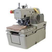
Brother RH-981A Service Manual (138 pages)
ELECTRONIC EYELET BUTTON HOLER
Brand:
Brother
| Category:
Sewing Machine
| Size: 2.2 MB
Table of Contents
Table of Contents
6
1 Mechanical Descriptions
9
Upper and Lower Shaft Mechanisms
9
Needle Bar Mechanism
10
Thread Take-Up Mechanism
10
Zigzag Mechanism
11
Needle Bar Rocking Mechanism
11
Feed Mechanism
12
Work Clamp Mechanism
13
Cloth Opener Mechanism
14
Cutter Mechanism
15
1-10.Looper Mechanism
15
1-11.Spreader Mechanism
16
1-12.Double Chain Stitch Looper Mechanism
17
2 Disassembly
18
Covers and Work Clamp Mechanism
18
Feed Mechanism
19
Lubrication Mechanism
19
Looper and Spreader Mechanisms
20
Needle Bar Rotating Mechanism
21
Looper Base Mechanism
22
Needle Bar, Thread Take-Up, and Zigzag Mechanisms
23
Knife Pipe Assembly
25
Lower Shaft Mechanism
25
2-10.Synchronizer Mechanism
26
2-11.Upper Shaft Mechanism
26
2-12.Cutter Mechanism
27
2-13.Zigzag Fork Mechanism
27
3 Assembly
28
Zigzag Fork Mechanism
28
Cutter Mechanism
29
Upper Shaft Mechanism
30
Lower Shaft Mechanism
31
Adjusting the Timing Belt
31
Upper Thread Trimmer Mechanism
32
Adjusting the Thread Trimmer Lever Hammer Stroke
32
Knife Pipe and the Knife Bracket
33
Driving Gear Shaft Mechanism
34
Needle Bar, Thread Take-Up, and Zigzag Mechanisms
35
Eliminating End Play of the Thread Take-Up on the Arm
35
Applying Grease to the Ends of the Thread Take-Up Spring
35
3-8-3.Eliminating End Play of the Needle Bar Driving Lever
35
3-8-4.Eliminating End Play of the Driving Rod
36
Of Ball Bearing 25/20
36
3-8-6.Eliminating End Play of the Zigzag Rock Shaft
36
3-8-7.Eliminating End Play of the Zigzag Lever
37
The Needle Bar Level Feed Link
37
3-8-9.Attaching the Needle Bar Bush U and the Needle Bar
38
Eliminating End Play of the Needle Bar Block
39
Adjusting the Needle Bar in the Radial Direction
39
Attaching the Needle Bar Block Assembly
40
Adjusting the Height of the Needle Bar
40
Looper Base
41
3-10.Needle Bar Rocking Mechanism
42
Driving Looper Shaft
42
Needle Bar Rocking Mechanism
43
3-11.Looper and Spreader Machanisms
45
3-12.Lubrication Mechanism
48
Machine Head
48
Driving Gear Shaft
49
3-13.Feed Mechanism
50
Direction
50
Y Direction
51
Attaching the X-Feed Guide Shaft
53
3-14.Synchronizer
54
3-15.Covers and Work Clamp Mechanism
55
3-16.Safety Switch
55
4 Adjustment
56
Adjusting the Work Clamp Lift Height
56
Adjusting the Position of the Work Clamp Plate
57
Adjusting the Cloth Opening Amount
58
Adjusting the Position of the Work Clamp
59
Adjusting the X-Axis Home Position
60
Adjusting the Y-Axis Home Position
60
Adjusting 0 Position (Reference Line) of the Needle
61
Adjusting the Home Position of the Looper Base
61
Fine Adjustment of Knife Position
62
4-10.Adjusting the Sideways Movement of the Cutter Lever
63
4-11.Adjusting the Height of the Throat Plate
63
4-12.Adjusting the Height of the Spreader and Looper
64
4-13.Adjusting the Needle and Looper Timing
65
4-14.Adjusting the Loop Stroke
66
4-15.Adjusting the Height of the Needle Bar
67
4-16.Adjusting the Clearance between the Looper and Needle
67
4-17.Adjusting the Needle Guard
68
4-18.Adjusting the Spreader Mounting Positions
68
4-19.Adjusting the Spreader Timing
69
4-20.Adjusting the Amount to Pull the Upper Thread and Tension Release
69
4-21.Adjusting Upper Thread Trimming
70
Adjusting the Upper Movable Knife Mounting Position
70
Adjusting the Position of the Thread Trimmer Lever Bracket
71
4-22.Adjusting the Lower Thread Trimmer (-01 Specification)
71
4-22-1.Adjusting the Knife Pressure
71
Thread Trimmer Arm
72
And Thread Clamp Opener
73
4-22-4.Adjusting the Thread Handler
74
4-22-5.Adjusting the Thread Guide Plate
75
Thread Required for Thread Trimming
75
Thread for Safety Stitching
76
4-22-8.Adjusting the Amount to Pull the Gimp
76
4-23.Adjusting the Lower Thread Trimmer (-02, -52 Specifications)
77
Adjusting the Knife Engagement
77
Adjusting the Knife Pressure
78
Adjusting the Gimp Pull Force
78
Adjusting the Gimp Tension
79
Using Gimp Thread Work Clamp
80
Adjusting the Auxiliary Clamp Arm
81
Adjusting the Length of the Lower Thread to be Pulled for a Safe Sewing Start
82
4-24.Adjusting the Position of the Lower Thread Presser (-02, -52 Specifications)
83
4-25.Adjusting the Rotating Centers of the Needle Bar and the Looper Base
84
4-26.Adjusting the Needle Bar Stop Position
85
5 Power Supply Equipment
86
Components Inside the Control Box
86
Fuse Explanation
88
5-2-1.Before Replacing a Fuse
89
Connectors
90
5-3-1.Connector Positions
90
5-3-2.Signal Names for Connectors and Probable Symptoms Due to Poor Contact
94
Specification Harness Connections
105
Summary of DIP Switches
106
5-5-1.Panel DIP Switches
106
Circuit Board DIP Switches
107
Changing Functions Using the Memory Switches
109
Memory Switch Table
110
Sensors Positions and Funstions
111
6 Air Pressure Mechanism
115
Solenoid Valves and Air Tubes
115
6-1-1.Adjusting the Solenoid Valve Speed Controllers
115
6-1-2.Air Tubes
116
Air Tube Layout
117
7 Software
120
Motion Flowchart
120
Input Check List
121
Output Check List
124
List of Error Codes
126
Troubleshooting
129
Control Circuit Block Diagram (1)
136
Control Circuit Block Diagram (2)
137
Advertisement
Brother RH-981A Instruction Manual (89 pages)
ELECTRONIC EYELET BUTTON HOLER
Brand:
Brother
| Category:
Sewing Machine
| Size: 1.8 MB
Table of Contents
Safety Instructions
2
Notes on Safety
3
Maintenance and Inspection
4
Warning Labels
5
Table of Contents
6
1 Names of each Part
8
2 Specifications
9
Sewing Shape
10
Optional Parts
10
PD-9810, Programmer
10
Replacement Parts List for Specification Changes
11
3 Installation
12
Table Processing Diagram
12
Installing the Motor
13
Installing the Motor Pulley
14
Installing the Control Box
14
Installing the Machine Head
15
Installing the Oil Container
17
Installing the Operation Panel
17
Tightening the V-Belt
18
Installing the Spool Stand
19
3-10.Installing the Hand Switch
19
3-11.Installing the Air Unit and the Valve Unit
19
Connecting the Wiring
20
Connections Inside the Control Box
21
Connecting the Motor Cables
22
Connecting the Air Tubes
22
Securing the Cables
23
3-13.Connecting the Air Tubes
24
Adjusting the Air Pressure
24
3-14.Connecting the Power Cord
25
3-15.Installing the Programmer (Sold Separately)
26
3-16.Installing the Foot Switch (Option)
26
3-17.Installing the Indexer (Option)
27
Installing the Indexer Main Unit
27
Installing the Upper Thread Presser
28
Replacing the Plate Presser and Presser Plate
28
Installing the Valve Unit
28
Connecting the Connectors
29
Connecting the Air Tubes
30
Securing the Air Tubes and Cables
30
Installing the Hand Switch
31
4 Lubrication
32
Adding Oil
32
5 Correct Use
34
Data Initialization
34
Changing the Lower Thread and Gimp Trimming
34
Installing the Needle
35
Threading the Upper Thread
35
Threading the Lower Thread
36
Threading the Gimp
37
Setting the Material
38
Setting the Installation Position for Cloth Feed Plate (L) (-52 Specifications)
40
Replacing the Proms
41
6 Operation
42
Name and Function of each Operation Panel Item
42
Starting up
43
Program Setting Method
44
Parameter Table ( Taper Bar )
44
Parameter Table ( Straight Bar Tacking )
47
Cycle Program
50
Production Counter
51
Using the Program Memos
51
7 Sewing
52
Automatic Sewing
52
Using the EMERGENCY STOP Switch
53
Adjusting the Thread Tension
54
Needle and Knife Position
55
Setting the Feed Bracket to the Front Position
56
Switching between Single-Pedal and Dual-Pedal Operation
56
Using Test Feed Mode
57
Using Manual Mode
58
Changing the Mode During an Operation
59
7-10.Moving the Cloth Feed Bar (-52 Specifications)
59
8 Cleaning and Maintenance
60
Cleaning
60
Draining the Oil
61
Checking the Air Filter
61
9 Standard Adjustments
62
Adjusting the Height of the Spreader and Looper
62
Adjusting the Needle and Looper Timing
63
Adjusting the Loop Stroke
64
Adjusting the Height of the Needle Bar
65
Adjusting the Clearance between the Looper and Needle
65
Adjusting the Needle Guard
66
Adjusting the Spreader Mounting Positions
66
Adjusting the Spreader Timing
67
Adjusting the Needle Racking Width (Stitch Width)
67
9-10.Changing the Knife Cutting Length (Replacing the Hammer)
68
9-11.Adjusting the Contact between the Knife and the Hammer
69
9-12.Replacing the Knife
70
Adjusting the Cutting Pressure
70
Adjusting the Position of the Work Clamp Plate
71
Adjusting the Cloth Opening Amount
72
Adjusting the Trimming of the Upper Thread
73
Adjusting the Trimming of the Lower Thread and Gimp
73
9-18.Adjusting the Gimp Length after Trimming
74
(-02, -52 Specifications)
74
9-19.Lower Thread Presser (-02, -52 Specifications)
74
9-20.Auxiliary Clamp Arm (-02, -52 Specifications)
75
9-21.Adjusting the Cloth Feeding Speed (-52 Specifications)
75
9-22.Adjusting the Cloth Feed Bar Home Position (-52 Specifications)
76
9-23.Adjusting the Indexer Hole Spacing (-52 Specifications)
77
9-24.Adjusting the Position of Limit Switch L (-52 Specifications)
78
9-25.Adjusting the Position of Limit Switch R (-52 Specifications)
78
10 Changing Functions Using the Memory Switches
79
10-1.Memory Switch Table
80
11 Changing Functions Using the Dip Switches
81
Panel DIP Switches
81
Circuit Board DIP Switches
82
12 List of Error Codes
84
13 Troubleshooting
87
Instruction Manual
89
Brother RH-981A Parts Manual (109 pages)
Electronic eyelet button holder
Brand:
Brother
| Category:
Sewing Machine
| Size: 5.39 MB
Table of Contents
Notes for Using this Parts Book
4
Contents
4
Machine Body
5
Needle Bar and Thread Take-Up Mechanism
9
Upper Shaft Mechanism
13
Zigzag Mechanism
13
Needle Bar Rocking Mechanism
15
Presser Foot Mechanism
17
Presser Foot Mechanism (Jeans Specification)
21
Feed Mechanism
25
Cutter Mechanism
29
Tension Pulley Mechanism
31
Lower Shaft Mechanism
31
Double Chain Stitch Looper Mechanism
33
Upper Thread Trimmer
37
Jeans Specification
37
Upper and Lower Thread Trimmer
37
Option Parts
37
Looper Mechanism
39
Spreader Mechanism
39
Lubrication
41
Threading Mechanism
43
Thread Trimmer Mechanism
47
Thread Trimmer Mechanism (Jeans Specification)
49
Upper Thread Trimmer Mechanism
51
Synchronizer
51
Control Box Mechanism
53
Air Pressure Mechanism
61
Power Supply Equipment Mechanism
69
Cloth Control System Mechanism
71
Foot Switch Pedal Mechanism
75
Attachment Set
77
Accessories
89
Different Parts List
93
Work Clamp
95
Needle Plate
96
Hammer
96
Knife
97
Harness
97
Warning Labels
98
Index
99
Advertisement
Brother RH-981A Instruction Manual (65 pages)
Industrial Sewing Machine Programmer
Brand:
Brother
| Category:
Sewing Machine
| Size: 0.56 MB
Table of Contents
Table of Contents
5
Chapter 1 INTRODUCTION
7
Name of Parts and Function
8
Illustration on the Screen Shows
10
Menu Screen
10
Program No. Selection Screen
11
Parameter Setting Screen
12
Screen Directory
13
Chapter 2 PREPARATION
15
Connecting the Programmer to the Machine
16
Power ON/OFF
17
Set the Power to on
17
Set the Power to off
17
Putting the Programmer in Store
18
Chapter 3 EXAMPLE of the PROGRAM CHANGE PROCEDURE
19
Parameter Changing of the Program
20
Chapter 4 PARAMETER
23
Parameter Table
24
When the Programmer Is Connected to the Machine with the Taper Tack Specifications
24
When the Programmer Is Connected to the Machine with the Straight Bar Tack Specifications
27
Parameter Selection
30
Selection with the [SHORT CUT] Key
30
Selection with the [ ] Key
30
Changing the Parameter
31
Chapter 5 PROGRAM READING and WRITING
33
Program Reading from the Machine
34
Program Writing to the Machine
35
Program Reading from the File
36
Program Writing to the File
37
Chapter 6 HANDY FUNCTIONS
39
Auto Read/Write Setting
40
When the Auto Read/Write Setting Is on
40
When the Auto Read/Write Setting Is off
40
When the [MENU] Key and the [P] Key Are Concurrently Pressed
40
File Saving Function
41
Chapter 7 OTHER FUNCTIONS
43
Data Saving to Another Machine
44
Saving Area
44
Saving Method
44
Cycle Program Setting
46
Display of the Program Nos. for the Machine at Cycle Program Writing
48
Initializing the Program in the Work Area
49
Initializing All of the Program
49
Initializing One of any Programs
49
Initializing All of the Program in the Environment Setting Area and Work Area
50
Environment Setting
51
Language Used
51
Setting Numbers of the Program to Read and Write
52
Enable/Disable for Auto Read/Write
52
Display/Non-Display of the Check Message
53
PROM Version Display
54
Comparing the Program
55
Comparing with the Data in the Machine
55
Comparing with the Data in the Programmer
56
Copying the Program
57
PROM Exchange Procedures
58
Change to Factory Settings
61
Chapter 8 ERROR MESSAGE
63
List of Messages
64
Data Version Unmatch Error
64
Received Data Error
64
Commnunication Error
64
Data Lost Error
64
Instruction Manual
65
Brother RH-981A Specifications (8 pages)
Electronic Eyelet Button Holer
Brand:
Brother
| Category:
Sewing Machine
| Size: 0.47 MB
Table of Contents
Specifications
1
Replacement Parts List for Specification Changes
2
Needle Plate
7
Throat Plate
8
Advertisement
Related Products
Brother RH-9820
Brother RH-9800
Brother RH-9800-52
Brother RH-9800-55
Brother RH-981A-00
Brother RH-981A-01
Brother RH-981A-02
Brother RH-981A-52
Brother RH-9820-00
Brother RH-9820-01
Brother Categories
Sewing Machine
All in One Printer
Printer
Label Maker
Fax Machine
More Brother Manuals
Login
Sign In
OR
Sign in with Facebook
Sign in with Google
Upload manual
Upload from disk
Upload from URL