Brother RH-981A Instruction Manual
Electronic eyelet button holer
Hide thumbs
Also See for RH-981A:
- Service manual (138 pages) ,
- Parts manual (109 pages) ,
- Instruction manual (65 pages)
Table of Contents
Advertisement
Advertisement
Table of Contents

Related Manuals for Brother RH-981A


Summary of Contents for Brother RH-981A
- Page 1 RH-981A ELECTRONIC EYELET BUTTON HOLER...
-
Page 2: Safety Instructions
........This symbol ( ) indicates something that you must do. The picture inside the circle indicates the nature of the thing that must be done. (For example, the symbol at left means “you must make the ground connection”.) RH-981A... -
Page 3: Notes On Safety
Furthermore, do not drink the oil or eat the grease with correct operation may also occur. under any circumstances, as they can cause vomiting and diarrhoea. Keep the oil out of the reach of children. RH-981A... -
Page 4: Maintenance And Inspection
Disconnect the air hoses from the air supply and wait for the needle on the pressure gauge to drop to “0” before carrying out inspection, adjustment and repair of any parts which use the pneumatic equipment. RH-981A... -
Page 5: Warning Labels
Be sure to connect the ground. If the ground connection is not secure, you run a high risk of receiving a serious electric shock, and problems with correct operation may also occur. Needle bar guard Direction of operation Eye guard Belt cover (Rear) Finger guard Belt cover 3122Q RH-981A... -
Page 6: Table Of Contents
......... 55 4. LUBRICATION ............25 9-2. Adjusting the needle and looper timing... 56 4-1. Adding oil ............25 9-3. Adjusting the loop stroke........57 4-2. Lubrication ............25 9-4. Adjusting the height of the needle bar..... 58 RH-981A... - Page 7 ......72 10-1.Memory switch table ........73 11. CHANGING FUNCTIONS USING THE DIP SWITCHES ........74 11-1. Panel DIP switches ........74 11-2. Circuit board DIP switches......75 12. LIST OF ERROR CODES ......77 13. TROUBLESHOOTING ........80 RH-981A...
-
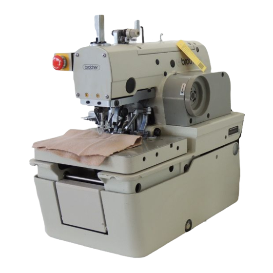
Page 8: Names Of Each Part
(3) Cloth presser switch (4) Start switch (5) EMERGENCY STOP switch (6) Upper shaft pulley (7) Feed bracket (8) Spool stand (9) Power switch (10) Motor (11) Operation panel (12) Control box Fly indexer (-52 specifications) Fly indexer 2380Q RH-981A... -
Page 9: Specifications
* -02 and -52 specifications are further divided into L1 - L7 specifications in accordance with the stitch length. Please be sure to specify the stitch length when ordering. Specification RH-981A-00 RH-981A-01 RH-981A-02, RH-981A-52 Application Men’s clothes and ladies’ clothes Jeans and work clothes Sewing speed 1,000 - 2,200rpm (100-rpm steps) -
Page 10: Sewing Shape
You can use the icon keys to retrieve parameters at a single touch, and to display them as icons on the LED screen so that the settings can be changed easily. It allows you to easily transfer data between different sewing machines. 2381Q RH-981A... -
Page 11: Replacement Parts List For Specification Changes
S37201-001 (34) S41474-101 S37201-001 (34) S43366-000 S42139-101 (36 - 40 mm) S41475-101 S35093-001 (38) Note: There is 10 mm of difference in the knife cutting position between L1 - L4 and L5 - L7 specifications. (Refer to page 63.) RH-981A... -
Page 12: Installation
The top of the table should be 50 mm in thickness and should be strong enough to hold the weight and withstand the vibration of the sewing machine. Drill holes in the table as shown in the diagram below. 0800Q * There is the special table indicated below. Model code Table/legs assembly 127-981-04902 RH-981A... -
Page 13: Installing The Motor
(8) onto the motor base plate (9), and then install the motor as shown in the illustration. Note: The vibration of the motor may cause the bolts to come loose. Make sure that the bolts are securely tightened. 3125Q RH-981A... -
Page 14: Installing The Motor Pulley
3. Align the control box (2) with the nuts (1), and then install it with the four flat washers (3), spring washers (4) and bolts (5). Note: Be careful not to drop any small parts such as washers onto the circuit board when installing the bolts. 3128Q RH-981A... -
Page 15: Installing The Machine Head
Make sure that steps 2. to 4. above have been completed before raising the machine head. 2982Q 6. Install the bed base cover (9) to the rear of the bed (10) with the four screws (11). Note: Be careful not to injure yourself on the spring hinge. RH-981A... - Page 16 Pull the machine head down toward you gently, remove the head support lever (2) from the hinge lever support shaft (3), and then gently lower the machine head. Note: Do not hold the machine head by the feed bracket (4) or X feed shaft A (5) when it is being raised and lowered. RH-981A...
-
Page 17: Installing The Oil Container
(5) can be opened and closed. 3. Insert the connector cord (6) into the control box Table through the hole at the side of the box. Bottom of work table Table 2988Q RH-981A... -
Page 18: Tightening The V-Belt
5. Install the motor cover (5) with the three screws (6). Note: After a long period of use, the V-belt will become run in and will loosen around the motor pulley. When this happens, turn off the power and adjust by the procedure given in step 4. above. RH-981A... -
Page 19: Installing The Spool Stand
3. Connect air tube No. 15 to the intermediate joint (5) of the air unit (1) and to the joint (6) of the valve unit (3), and connect air tube No. 16 to joints (7) and (8). Connecting the valve cables Insert the cable (9) which is coming out of the valve unit to the 2-pin connector (10) of the valve cable assembly. RH-981A... -
Page 20: Connecting The Wiring
3. Connect the hand switch connector (8) to the control box connector. 4. Install the power switch (9) to the underside of the work table with the two screws (10). 5. Secure the cables using staples (11) (in four locations). 3131Q RH-981A... -
Page 21: Connections Inside The Control Box
PMD circuit circuit board or the heat sink. Furthermore, Board adjust the lengths of the cables from outside the control box so that there is no looseness in the cables inside the control box. 2999Q RH-981A... -
Page 22: Connecting The Motor Cables
(Auxiliary clamp arm *2) Work clamp If the lower thread trimmer is not installed, solenoid valve [3] is not used. The auxiliary clamp arm can only be used machines with specification. Plug 4 0826Q < -02 > 0828Q 0829Q RH-981A... -
Page 23: Securing The Cables
Right/left work clamp No. Label No. Specification Right/left movable knife No. of harness Thread handler No. -00, -01 * There is 10 mm of difference in the knife installation positions between L1 - L4 and L5 - L7. 3004Q RH-981A... -
Page 24: 3-13.Connecting The Air Tubes
(0.3Mpa) 4. To reduce the air pressure, gently lift knob (2) or (0.5Mpa) knob (4) and turn it counterclockwise. 5. Open the cock (5). Air will enter the reservoir and the needle will move To loosen To tighten 3007Q RH-981A... -
Page 25: 3-14.Connecting The Power Cord
2. Insert the plug into properly-grounded AC power supply. Note: Do not use extension cords, otherwise machine operation problems may result. Single phase Green and yellow wire (ground wire) 3133Q Three phase Green and yellow wire (ground wire) 3134Q RH-981A... -
Page 26: 3-15.Installing The Programmer (Sold Separately)
1. Install the programmer support (2) to the work table with the two screws (1). 2. Insert the programmer connector (4) securely into the left side of the operation panel (3). 3-16. Installing the foot switch (option) Insert the connector (3) of the foot switch (2) into the control box connector (1). 3135Q RH-981A... -
Page 27: 3-17.Installing The Indexer (Option)
* Push down the chuck pin (16) and check that it goes smoothly into all of the holes in the cloth feed bar (13). If it does not go in smoothly, re-adjust the installation positions of feed base (L) (9) and feed base (R) (12). 3018Q RH-981A... -
Page 28: Installing The Upper Thread Presser
1. Install the valve unit (1) with the screw (2). 2. Remove the stopper plug (with the P mark) (4) from the valve unit (3), and then install the joint (5). 3. Connect the 6mm-diameter air tube (7) to joints (5) and (6). RH-981A... -
Page 29: Connecting The Connectors
3024Q Switch pin Cable color 15-pin Connector Limit switch White (R) (6) Black Limit switch White (L) (7) Black Brown (Red) Cylinder Black (White) sensor (8) Blue (Black) 8. Secure the cable with the cable clamp (9). 3025Q RH-981A... -
Page 30: Connecting The Air Tubes
2. Secure the air tube (2) and cable (3) with the cord holder (4), screw (length 16 mm) (5) and washer (6). * Leave enough slack in the air tube (2) and cable (3) at this time to allow for the movement of the feed bracket (7). RH-981A... -
Page 31: Installing The Hand Switch
1. Install the hand switch support plate (1) with the two screws (2) in the position shown in the illustration. 2. Install the hand switch (3) to the hand switch support plate (1) with the two screws (4). 3027Q RH-981A... -
Page 32: Lubrication
When oiling, some oil will get onto the thread. Carry out a test sewing to ensure that your material does not get stained with oil. Oiling the needle bar and cam Add 2-3 drops of oil in the places indicated by the arrows. 0861Q RH-981A... - Page 33 10. Add 5 - 6 drops of oil to the felt (18) which is attached to the sliding surfaces of the looper base and the bed. 11. Close the front cover. 12. Install the work clamp plates by carrying out the steps 5., 4. and 3. in that order. RH-981A...
-
Page 34: Correct Use
3. Open the rear plate (2) of the control box. 4. Set DIP switch C (3) No. 6 on the circuit board to OFF. 5. Close the rear plate (2) and tighten the six screws (1). No trimming 3037Q RH-981A... -
Page 35: Installing The Needle
Turn off the power switch before threading the thread, otherwise the machine may operate if the start switch is pressed by mistake, which could result in injury. Thread the upper thread as shown in the illustration below. * Use the accessory needle threader (1). 0876Q 0875Q <-52 specifications> 2403Q 0878Q 0874Q RH-981A... -
Page 36: Threading The Lower Thread
Remove the work clamp plates (refer to page 26), and then thread the lower thread as shown in the illustration below. For upper thread trimming specifications (-00) 0880Q 0881Q 0879Q For upper and lower thread trimming specifications (-01, -02 and -52) 0883Q 0882Q 0881Q RH-981A... -
Page 37: Threading The Gimp
Remove the work clamp plates (refer to page 26), and then thread the gimp as shown in the illustration below. Once threading is complete, replace the work clamp plates. 0885Q <-00,-01> 0884Q <-02,-52> Pass the gimp through the hole of the thread tension stud (1). Refer to “9-18. Adjusting the gimp length after trimming” (Page 67). 3041Q RH-981A... -
Page 38: Setting The Material
Loosen the four screws (5), and then move horizontal cloth set guide (L) (2) and horizontal cloth set guide (R) (3) forward or back to adjust. 3. The horizontal sewing margin can be adjusted between 30 - 40 mm. Loosen the two screws (6), and move the vertical cloth set guide (4) to the left or right to adjust. RH-981A... - Page 39 * After the last buttonhole is sewn, the cloth feed bar returns to the left setting position. Horizontal setting position The cloth is set to both the left setting position and right setting position. * The next piece of cloth is set at the position that the last buttonhole was sewn. RH-981A...
-
Page 40: Setting The Installation Position For Cloth Feed Plate (L) (-52 Specifications)
(C) 167.5 - 177.5 mm (G) 279.5 - 289.5 mm (D) 142.5 - 152.5 mm (H) 270.5 - 280.5 mm (I) 234.5 - 244.5 mm (J) 209.5 - 219.5 mm (K) 195 - 205 mm 0897Q (L) 184.5 - 194.5 mm RH-981A... -
Page 41: Replacing The Proms
This PROM is mounted in position (2). 3047Q <Panel circuit board> The PROM which is marked “PL” is the panel PROM. This PROM is mounted in position (3). * The figure inside the box indicates the version number. 2430Q 3048Q RH-981A... -
Page 42: Operation
Illuminates when cutting after sewing has been set. (9) AFTER key Press to set cutting after sewing. (10) Automatic mode indicator Illuminates during automatic mode. (11) Test feed mode indicator Illuminates during test feed mode. (12) Manual mode indicator Illuminates during manual mode. RH-981A... -
Page 43: Starting Up
2. Press the start switch (24). * The feed bracket will move to the cloth setting position. * The panel displays will return to the same displays as when sewing last finished. 3137Q RH-981A... -
Page 44: Program Setting Method
(L6): 32 - 36 mm (L6): 34 mm (L7): 36 - 40 mm (L7): 38 mm Tacking length 0 - 20 mm *1 The Button hole length setting value and the default value vary depending on the machine sub-class. RH-981A... - Page 45 Cutting space -0.3 - 0.5 mm Knife X position compensation -0.5 - 0.5 mm Knife Y position compensation -0.7 - 0.7 mm Start tying stitches 0 - 2 End tying stitches 0 - 2 X alignment -1 - 6 RH-981A...
- Page 46 *2 The standard eyelet machine speed is the value that has been set by parameter 00 (sewing speed). *3 If the sewing speed is set to a speed that is slower than the slow start speed, the slow start speed used for sewing will be the same as the normal sewing speed. RH-981A...
-
Page 47: Parameter Table ( Straight Bar Tacking )
5 - 18 stitches Stitch pitch 0.5 - 2.0 mm Number of eyelet stitches 4 - 20 stitches Cutting space -0.3 - 0.5 mm *1 The Button hole length setting value and the default value vary depending on the machine sub-class. RH-981A... - Page 48 -1 - 6 θ1 alignment -3 - 3 θ2 alignment -3 - 3 Eyelet machine speed (*2) -600 - 0 rpm *2 The standard eyelet machine speed is the value that has been set by parameter 00 (sewing speed). RH-981A...
- Page 49 OFF, 1 - 9 (Specify copy source) *3 If the sewing speed is set to a speed that is slower than the slow start speed, the slow start speed used for sewing will be the same as the normal sewing speed. RH-981A...
-
Page 50: Cycle Program
10. Press the OFF key (6) so that the "." disappears, and then press the ENTER key (5) to accept the "3" setting. 11. Press the SELECT key (1). Cycle program mode will end and the mode will change to automatic mode. 2411Q RH-981A... -
Page 51: Production Counter
If you do so, additions can be removed using an eraser and the space can be re-used. The program notes are useful for recording what patterns have been entered into which programs. 3054Q RH-981A... -
Page 52: Sewing
6. Press the start switch (9). Sewing will then start. 7. When sewing is finished, the work clamp will be raised. * The production counter value in the detail display (3) will increase by 1. 8. To repeat this operation, repeat steps 5 and 6 above. RH-981A... -
Page 53: Using The Emergency Stop Switch
• To stop sewing, press the RESET key (5). (The feed bracket will return to the cloth setting position.) In test feed mode or in manual mode: • Press the RESET key (5). (The feed bracket will return to the cloth setting position.) RH-981A... -
Page 54: Adjusting The Thread Tension
(5). Stroke adjustment Loosen the screw (6) and turn the thread take-up spring guide (7) in the direction indicated by the arrow to increase the stroke of the spring (5). 3061Q RH-981A... -
Page 55: Needle And Knife Position
When cutting after sewing, set the cutting space to an 0938Q appropriate value so that the seam is not cut by the knife. * The cutting space should generally be set to around 0.2. (Refer to “6-3 Program setting method.”) Cutting space RH-981A... -
Page 56: Setting The Feed Bracket To The Front Position
4. Sewing can then be carried out as normal. (Refer to “7-1. Automatic sewing”.) Note: During single pedal operation, when the start switch is pressed, the work clamp is lowered and sewing starts straight away. If you would like to reset the material, set to dual-pedal operation. RH-981A... -
Page 57: Using Test Feed Mode
* The number of stitches in the detail display (3) will increase by 2. 8. When the final stitch is reached, the buzzer will sound. 9. After releasing the start switch (6), press it once more. * The feed bracket (7) will return to the cloth setting position. RH-981A... -
Page 58: Using Manual Mode
When the needle up position is reached, press the start switch (6). * Thread trimming will be carried out, and then the machine will return to the cloth setting position. Note: If cutting after sewing has been selected, the hammer will operate. RH-981A... -
Page 59: Changing The Mode During An Operation
While pressing the RESET key (1), press the or the key. The cloth feed bar will then move in the right direction or the left direction. * This operation is only possible when the cloth feed plate is in the left setting position (home condition). 3068Q RH-981A... -
Page 60: Cleaning And Maintenance
4. Check the oil level by looking at the sight glass. If the oil level is low, replenish the oil supply. <-52 specifications> 0931Q 0940Q 5. Remove any thread scraps and dust which have collected in the holes of the cloth feed bar. 6. Wipe away any thread scraps and dust which are adhering to the feed guide shaft. RH-981A... -
Page 61: Draining The Oil
Note: Clean up any oil that may have been spilt onto the floor. 3145Q 8-3. Checking the air filter 1. Close the air cock (1). 2. Turn the screw (2) to release any air and water in the drain. 3070Q RH-981A... -
Page 62: Standard Adjustments
2. The clearance between the right looper (9) and the right spreader (1) should be as small as possible. 3. If adjustment is necessary, loosen the screw (10) and then move the eye looper (8) and right looper (9) up or down. RH-981A... -
Page 63: Adjusting The Needle And Looper Timing
5. If adjustment is necessary, turn the looper base (6) in the direction indicated by the arrow in the illustration, loosen the screw (7), and then move the looper link clamp (8) up or down to tilt the LS-holder bracket (9) to the left or right (in the direction of the arrow). RH-981A... -
Page 64: Adjusting The Loop Stroke
(6). Once they are aligned, tighten the two screws (3). After adjusting, check that the screws have been adequately tightened. Once this adjustment has been carried out, repeat the procedure given in "9-2. Adjusting the needle and looper timing". RH-981A... -
Page 65: Adjusting The Height Of The Needle Bar
If the clearance is not uniform, adjust the turning center for the needle bar. (This adjustment is made at the time of shipment from the factory.) * After making the adjustment in step 1. above, carry out the adjustment procedure given in "9-7. Adjusting the spreader mounting positions". RH-981A... -
Page 66: Adjusting The Needle Guard
(5) is aligned with the tip of the right looper (6). Note: Both the left spreader (1) and right spreader (5) should be installed so that they do not project past the tips of the eye looper (2) and right looper (6) respectively. RH-981A... -
Page 67: Adjusting The Spreader Timing
The stitch width becomes smaller as the adjustment screw (2) is moved upward. Note: If the needle racking width is changed greatly, you should re-adjust the timing between the needle and the loopers. (Refer to "9-2. Adjusting the needle and looper timing".) RH-981A... -
Page 68: 9-10.Changing The Knife Cutting Length (Replacing The Hammer)
3. When installing the hammer, push in the pin (3) and then tighten the screw (1). * Do not use knives with different numbers on the same hammer. If knives with different numbers are used, accurate cutting will not be possible and the knife will be damaged. RH-981A... -
Page 69: 9-11.Adjusting The Contact Between The Knife And The Hammer
2. Filing the cutting surface of the hammer in which knife incision is deep 2-1. Grip the hammer in a vise. 2-2. File the surface of the hammer smoothly until a single knife incision can still be seen faintly. RH-981A... -
Page 70: 9-12.Replacing The Knife
* If the material cannot be cut cleanly, do not increase the cutting pressure over the maximum limit. Check the contact between the knife and the hammer, while referring to "9-11. Adjusting the contact between the knife and the hammer". 3093Q RH-981A... -
Page 71: Adjusting The Position Of The Work Clamp Plate
Note: Adjust the clearance between the throat plate (1) and the needle plate L in the same manner. * If the maximum stitch width correction amount is set to 2.0 mm, adjust the distance between the throat plate and the needle plate to more than 2.0 mm. RH-981A... -
Page 72: Adjusting The Cloth Opening Amount
3. Press the start switch. The feed bracket will move and then the left and right work clamp plates will open. 4. Use calipers to measure the distance b. 5. The difference between a and b is the opening amount. (Opening amount = a - b) RH-981A... -
Page 73: Adjusting The Trimming Of The Upper Thread
The gimp is held between thread nipper M (2) and thread nipper U (4) on the plate spring. 3. Adjust so that the edge of the fixed knife (6) and the index mark (8) on the movable knife (7) are aligned when the thread trimmer arm (5) is at the maximum stroke. RH-981A... -
Page 74: 9-18.Adjusting The Gimp Length After Trimming
9-19. Lower thread presser (-02, -52 specifications) The lower thread presser (1) operates at the same time as upper thread trimming is carried out. The end of the lower thread is securely held between the lower thread presser (1) and the throat plate (2). 3106Q RH-981A... -
Page 75: 9-20.Auxiliary Clamp Arm (-02, -52 Specifications)
B- side needle valve At a height of approximately 9.1 mm from the surface of the valve body (turned 7 full rotations from Maximum height the maximum height) (approx. 11.6 mm) Approx. Approx. 9.1 mm 9.6 mm 3109Q RH-981A... -
Page 76: 9-22.Adjusting The Cloth Feed Bar Home Position (-52 Specifications)
6. Check that the pin (5) fits smoothly into the home position hole (7) when the cloth feed bar (6) is touching the bolt (2). * If the pin (5) is not fitting smoothly, repeat the procedure in steps 1. to 5. 3111Q RH-981A... -
Page 77: 9-23.Adjusting The Indexer Hole Spacing (-52 Specifications)
44.45 mm (1-3/4”), move the stopper block (2) so that it is against the left-hand set screw collar (4) and secure it in this position. Use the same setting method if using other combinations of different hole intervals. 3115Q RH-981A... -
Page 78: 9-24.Adjusting The Position Of Limit Switch L (-52 Specifications)
3. Adjust the position of feed bar guide R (7) so that limit switch R (3) turns on when the roller (4) is pressed by the dog (6) of cloth feed plate R (5). 4. Tighten the two screws (1). RH-981A... -
Page 79: Changing Functions Using The Memory Switches
* The memory switch setting will stop flashing. 6. Repeat steps 3 to 5 to change other memory switch settings. 7. Press the SELECT key (1) to change the mode to automatic mode. * The memory switch settings will be memorized. RH-981A... -
Page 80: 10-1.Memory Switch Table
Accordingly it is recommended that you set home position starting to be carried out each time (setting "1"). (Note 2) If a program number has been set for memory switch No. 13, it will be ignored if a program number has been set for memory switch No. 14. RH-981A... -
Page 81: Changing Functions Using The Dip Switches
If this adjustment is not carried out, the throat plate and needle plate may interfere with each other. If the stitch width correction amount is set to more than 1.0 mm, the sewing speed will be limited in accordance with the value set. RH-981A... -
Page 82: Circuit Board Dip Switches
* If the maximum straight bar tacking length is set to 9.0 mm, it will be necessary to process the work clamp plate. Consult with your local Brother sales office for further details. If the work clamp plate is not processed, the throat plate may interfere with the needle plate and work clamp plate. RH-981A... - Page 83 11. CHANGING FUNCTIONS USING THE DIP SWICHES Circuit board DIP switch D 1001Q ON/OFF Setting items Default RH-981A...
-
Page 84: List Of Error Codes
2. Check that connector P18 on the control circuit board is properly connected. E-28 Panel communication start error 3. Check that connector P1 on the panel circuit board is properly connected. E-29 Machine motor communication start error Turn off the power. RH-981A... - Page 85 3. Check that connectors P9 and P21 on the control circuit board are properly connected. Needle up sensor is not activated within a Turn off the power and check that connector P2 on the control E-70 specified time. circuit board is properly connected. RH-981A...
- Page 86 Turn off the power and check that connector P20 on the control E-98 Power supply relay error circuit board is properly connected. Turn off the power and check that connectors P12 and P13 on the E-99 Power supply circuit board overcurrent error control circuit board are properly connected. RH-981A...
-
Page 87: Troubleshooting
Looper tip is blunt. one. Needle breaks. Needle is bent. Replace with a new needle. Needle and looper adjustment is Adjust the needle bar height or incorrect. the looper and spreader height. Needle needle guard Adjust correctly. adjustment is incorrect. RH-981A... - Page 88 Material is not being cut Adjust the cutting pressure so Cutting pressure is too weak. cleanly. that it is strong enough. Knife and hammer are not Grind the hammer surface. contacting properly. Knife is blunt. Replace with a new knife. RH-981A...
-
Page 89: Instruction Manual
INSTRUCTION MANUAL Printed in Japan 118-981 SA0279-101 2003.01.H (1)
Need help?
Do you have a question about the RH-981A and is the answer not in the manual?
Questions and answers
Error code 91
E 00 arızası nedir