Sign In
Upload
Manuals
Brands
AUMA Manuals
Controller
SAR 16.2
AUMA SAR 16.2 Manuals
Manuals and User Guides for AUMA SAR 16.2. We have
13
AUMA SAR 16.2 manuals available for free PDF download: Operation Manual, Operating Instructions Manual, Operation Instructions Manual, Manual
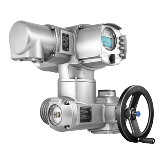
AUMA SAR 16.2 Operating Instructions Manual (104 pages)
Multi-turn actuators
Brand:
AUMA
| Category:
Controller
| Size: 2.94 MB
Table of Contents
Table of Contents
2
1 Safety Instructions
5
Prerequisites for the Safe Handling of the Product
5
Range of Application
5
Applications in Ex Zone 22 (Option)
6
Warnings and Notes
7
References and Symbols
7
2 Identification
8
Name Plate
8
Short Description
11
3 Transport and Storage
12
Transport
12
Storage
14
4 Assembly
16
Mounting Position
16
Valve Attachments
16
Design of Output Drive Type a
16
Design of Output Drive Types B and E
16
Handwheel Fitting
17
Multi-Turn Actuator: Mount to Valve/Gearbox
18
Stem Nut for Output Drive Type A: Finish Machining
18
Multi-Turn Actuator with Output Drive Type A: Mount
19
Multi-Turn Actuator with Output Drive Type B: Mount
20
Accessories for Assembly
21
Stem Protection Tube for Rising Valve Stem
21
Mounting Positions of Local Controls
22
Mounting Positions: Modify
22
5 Electrical Connection
23
Basic Information
23
Overview of AUMA Electrical Connections
25
SJ Electrical Connection (AUMA Plug/Socket Connector)
26
Terminal Compartment (for Mains Connection): Open
27
Cable Connection
28
Terminal Compartment (for Mains Connection): Close
29
Fieldbus Terminal Compartment: Open
30
Industrial Ethernet Cable: Connect
30
Fieldbus Terminal Compartment: Close
31
Compact Version SF Electrical Connection for Ethernet/Ip
32
Terminal Compartment (for Mains Connection): Open
33
Cable Connection
34
Terminal Compartment (for Mains Connection): Close
35
Industrial Ethernet Cable: Connect
36
Accessories for Electrical Connection
36
Actuator Controls on Wall Bracket
36
Parking Frame
37
External Earth Connection
38
Operation
39
Manual Operation
39
Manual Valve Operation
39
Motor Operation
40
Local Actuator Operation
40
Actuator Operation from Remote
41
Menu Navigation Via Push Buttons (for Settings and Indications)
41
Menu Layout and Navigation
42
User Level, Password
43
Password Entry
44
Password Change
44
Language in the Display
45
Language Change
45
Indications
47
Indications During Commissioning
47
Indications in the Display
47
Feedback Indications from Actuator and Valve
48
Status Indications According to AUMA Classification
50
Status Indications According to NAMUR Recommendation
51
Indication Lights of Local Controls
53
Optional Indications
54
Mechanical Position Indication (Self-Adjusting)
54
Mechanical Position Indication Via Indicator Mark (Not Self-Adjusting)
54
Signals (Output Signals)
55
Status Signals Via Output Contacts (Digital Outputs)
55
Assignment of Outputs
55
Coding the Outputs
55
Analogue Signals (Analogue Outputs)
55
Commissioning (Basic Settings)
56
Type of Seating: Set
56
Torque Switching: Set
57
Limit Switching: Set
58
Connection between Ethernet/Ip Module and Computer: Check
60
Ethernet/Ip Module Configuration
61
Test Run
63
Direction of Rotation at Mechanical Position Indicator: Check
63
Direction of Rotation at Hollow Shaft/Stem: Check
65
Limit Switching: Check
65
Advertisement
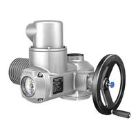
AUMA SAR 16.2 Operation Manual (108 pages)
Multi-turn actuators
Brand:
AUMA
| Category:
Controller
| Size: 6.51 MB
Table of Contents
Table of Contents
2
Safety Instructions
5
Prerequisites for the Safe Handling of the Product
5
Range of Application
5
Warnings and Notes
6
References and Symbols
6
Short Description
7
Name Plate
9
Transport and Storage
13
Transport
13
Storage
15
Assembly
17
Mounting Position
17
Handwheel Fitting
17
Mount Actuator to Valve
17
Overview of Output Drive Types
18
Output Drive Type a
18
5.3.2.1. Multi-Turn Actuator with Output Drive Type A: Mount
19
5.3.2.2. Stem Nut for Output Drive Type A: Finish Machining
21
Output Drive Types B/C/D and E
22
5.3.3.1. Multi-Turn Actuator with Output Drive Type B: Mount
23
Accessories for Assembly
24
Stem Protection Tube for Rising Valve Stem
24
Mounting Positions of Local Controls
25
Mounting Positions: Modify
25
Electrical Connection
26
Overview of AUMA Electrical Connections
26
Basic Information
26
SJ Electrical Connection (AUMA Plug/Socket Connector)
29
Terminal Compartment (for Mains Connection): Open
30
Cable Connection
31
Terminal Compartment (for Mains Connection): Close
32
Fieldbus Terminal Compartment: Open
33
Devicenet Cable: Connect
33
Fieldbus Terminal Compartment: Close
34
Accessories for Electrical Connection
35
Actuator Controls on Wall Bracket
35
Parking Frame
36
DS Intermediate Frame for Double Sealing
36
External Earth Connection
37
Operation
38
Manual Operation
38
Manual Valve Operation
38
Motor Operation
39
Operating the Actuator from Local Controls
39
Actuator Operation from Remote
40
Menu Navigation Via Push Buttons (for Settings and Indications)
40
Menu Layout and Navigation
41
User Level, Password
42
Password Entry
43
Password Change
43
Timeout for Incorrect Password Entry
44
Language in the Display
44
Language Change
44
Indications
46
Indications During Commissioning
46
Indications in the Display
46
Feedback Signals from Actuator and Valve
47
Status Indications According to AUMA Classification
49
Status Indications According to NAMUR Recommendation
50
Indication Lights of Local Controls
52
Optional Indications
53
Mechanical Position Indication Via Indicator Mark (Not Self-Adjusting)
53
Mechanical Position Indication (Self-Adjusting)
53
Signals (Output Signals)
54
Signals Via Devicenet
54
Status Signals Via Output Contacts (Digital Outputs)
54
Assignment of Outputs
54
Coding the Outputs
54
Analogue Signals (Analogue Outputs)
54
Commissioning (Basic Settings)
56
Type of Seating: Set
56
Torque Switching: Set
57
Limit Switching: Set
59
Settings at the Devicenet Gateway
61
Fieldbus Address and Baud Rate Setting
61
Termination
61
Input and Output Data
61
Led
70
Test Run
71
Direction of Rotation at Mechanical Position Indicator: Check
71
Direction of Rotation at Hollow Shaft/Stem: Check
73
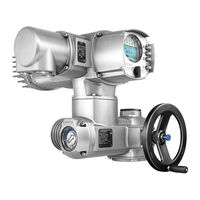
AUMA SAR 16.2 Operation Instructions Manual (96 pages)
Multi-turn actuators Control unit - electromechanical with actuator controls
Brand:
AUMA
| Category:
Controller
| Size: 2.6 MB
Table of Contents
Table of Contents
2
1 Safety Instructions
5
Prerequisites for the Safe Handling of the Product
5
Range of Application
5
Warnings and Notes
6
References and Symbols
6
2 Short Description
7
3 Name Plate
9
4 Transport and Storage
13
Transport
13
Storage
15
5 Assembly
16
Mounting Position
16
Handwheel Fitting
16
Mount Actuator to Valve
16
Overview of Output Drive Types
17
Output Drive Type a
17
5.3.2.1. Multi-Turn Actuator with Output Drive Type A: Mount
18
5.3.2.2. Stem Nut for Output Drive Type A: Finish Machining
20
Output Drive Types B/C/D and E
21
5.3.3.1. Multi-Turn Actuator with Output Drive Type B: Mount
22
Accessories for Assembly
23
Stem Protection Tube for Rising Valve Stem
23
Mounting Positions of Local Controls
24
Mounting Positions: Modify
24
6 Electrical Connection
25
Basic Information
25
SD Electrical Connection (AUMA Plug/Socket Connector)
28
Terminal Compartment (for Mains Connection): Open
29
Cable Connection
30
Terminal Compartment (for Mains Connection): Close
31
Fieldbus Terminal Compartment: Open
32
Fieldbus Cables: Connect
33
Fieldbus Terminal Compartment: Close
34
Accessories for Electrical Connection
35
Actuator Controls on Wall Bracket
35
Parking Frame
36
DS Intermediate Frame for Double Sealing
36
External Earth Connection
37
Operation
38
Manual Operation
38
Manual Valve Operation
38
Motor Operation
39
Operating the Actuator from Local Controls
39
Actuator Operation from Remote
40
Menu Navigation Via Push Buttons (for Settings and Indications)
40
Menu Layout and Navigation
41
User Level, Password
42
Password Entry
43
Password Change
43
Timeout for Incorrect Password Entry
44
Language in the Display
44
Language Change
44
Indications
46
Indications During Commissioning
46
Indications in the Display
46
Feedback Signals from Actuator and Valve
47
Status Indications According to AUMA Classification
49
Status Indications According to NAMUR Recommendation
50
Indication Lights of Local Controls
51
Optional Indications
52
Mechanical Position Indication Via Indicator Mark
52
Signals (Output Signals)
53
Status Signals Via Output Contacts (Digital Outputs)
53
Assignment of Outputs
53
Coding the Outputs
53
Analogue Signals (Analogue Outputs)
53
Commissioning (Basic Settings)
54
Type of Seating: Set
54
Fieldbus Address (Slave Address), Baud Rate, Parity and Monitoring Time: Set
55
Open Switch Compartment
55
Torque Switching: Set
56
Limit Switching: Set
57
End Position CLOSED (Black Section): Set
57
End Position OPEN (White Section): Set
57
Intermediate Positions: Set
58
Running Direction CLOSE (Black Section): Set
58
Running Direction OPEN (White Section): Set
59
Test Run
59
Direction of Rotation at Mechanical Position Indicator: Check
59
Direction of Rotation at Hollow Shaft/Stem: Check
60
Limit Switching: Check
61
Reference Operation Position Feedback: Perform
61
Close Switch Compartment
61
Advertisement
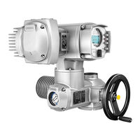
AUMA SAR 16.2 Operation Instructions Manual (100 pages)
Multi-turn actuators
Brand:
AUMA
| Category:
Controller
| Size: 2.74 MB
Table of Contents
Table of Contents
2
1 Safety Instructions
5
Basic Information on Safety
5
Range of Application
5
Applications in Ex Zone 22 (Option)
6
Warnings and Notes
6
References and Symbols
7
2 Identification
8
Name Plate
8
Short Description
11
3 Transport, Storage and Packaging
12
Transport
12
Storage
14
Packaging
14
4 Assembly
15
Mounting Position
15
Handwheel Fitting
15
Multi-Turn Actuator: Mount to Valve/Gearbox
15
Output Drive Type a
15
4.3.1.1. Stem Nut: Finish Machining
16
4.3.1.2. Multi-Turn Actuator (with Output Drive Type A): Mount to Valve
17
Output Drive Types B
18
4.3.2.1. Multi-Turn Actuator with Output Drive Types B: Mount to Valve/Gearbox
19
Accessories for Assembly
20
Stem Protection Tube for Rising Valve Stem
20
Mounting Positions of Local Controls
21
Mounting Positions: Modify
21
5 Electrical Connection
22
Basic Information
22
S/SH/SD Electrical Connection (AUMA Plug/Socket Connector)
24
Terminal Compartment (for Mains Connection): Open
26
Cable Connection
27
Terminal Compartment (for Mains Connection): Close
29
HART Terminal Compartment: Open (Version with HART Connection Board)
30
HART Cables: Connect
31
HART Terminal Compartment: Close (Version with HART Connection Board)
33
Accessories for Electrical Connection
34
Controls Mounted on Wall Bracket
34
Parking Frame
35
DS Intermediate Frame for Double Sealing
35
External Earth Connection
36
Operation
37
Manual Operation
37
Engage Manual Operation
37
Manual Operation: Disengage
37
Motor Operation
38
Local Actuator Operation
38
Actuator Operation from Remote
39
Menu Navigation Via Push Buttons (for Settings and Indications)
39
Menu Layout and Navigation
40
User Level, Password
41
Password Entry
41
Password Change
42
Language in the Display
42
Language Change
43
Indications
44
Indications During Commissioning
44
Indications in the Display
44
Feedback Indications from Actuator and Valve
45
Status Indications According to AUMA Classification
48
Status Indications According to NAMUR Recommendation
48
Indication Lights of Local Controls
50
Optional Indications
51
Mechanical Position Indication (Self-Adjusting)
51
Mechanical Position Indication Via Indicator Mark
51
Signals (Output Signals)
52
Signals Via HART
52
Status Signals Via Output Contacts (Digital Outputs)
52
Assignment of Outputs
52
Coding the Outputs
52
Analogue Signals (Analogue Outputs)
52
Commissioning (Basic Settings)
53
Type of Seating: Set
53
Torque Switching: Set
54
Limit Switching: Set
55
HART Address (Slave Address): Set
57
Test Run
58
Direction of Rotation at Mechanical Position Indicator: Check
58
Direction of Rotation at Hollow Shaft/Stem: Check
59
Limit Switching: Check
60
AUMA SAR 16.2 Operation Instructions Manual (92 pages)
Multi-turn actuators Control unit - electromechanical with actuator controls AC 01.2 Intrusive
Brand:
AUMA
| Category:
Controller
| Size: 2.29 MB
Table of Contents
Table of Contents
2
1 Safety Instructions
5
Basic Information on Safety
5
Range of Application
5
Applications in Ex Zone 22 (Option)
6
Warnings and Notes
6
References and Symbols
7
2 Identification
8
Name Plate
8
Short Description
11
3 Transport, Storage and Packaging
12
Transport
12
Storage
14
Packaging
14
4 Assembly
16
Mounting Position
16
Handwheel Fitting
16
Multi-Turn Actuator: Mount to Valve/Gearbox
16
Output Drive Type a
16
4.3.1.1. Stem Nut: Finish Machining
17
4.3.1.2. Multi-Turn Actuator (with Output Drive Type A): Mount to Valve
18
Output Drive Types B and E
19
4.3.2.1. Multi-Turn Actuator with Output Drive Types B: Mount to Valve/Gearbox
20
Accessories for Assembly
21
Stem Protection Tube for Rising Valve Stem
21
Mounting Positions of Local Controls
22
Mounting Positions: Modify
22
5 Electrical Connection
23
Basic Information
23
Electrical Connection S/SH (AUMA Plug/Socket Connector)
25
Terminal Compartment : Open
26
Cable Connection
27
Terminal Compartment : Close
28
Accessories for Electrical Connection
29
Actuator Controls on Wall Bracket
29
Parking Frame
30
DS Intermediate Frame for Double Sealing
30
External Earth Connection
31
Operation
32
Manual Operation
32
Engage Manual Operation
32
Manual Operation: Disengage
32
Motor Operation
33
Local Actuator Operation
33
Actuator Operation from Remote
34
Menu Navigation Via Push Buttons (for Settings and Indications)
34
Menu Layout and Navigation
35
User Level, Password
36
Password Entry
36
Password Change
37
Language in the Display
37
Language Change
37
Indications
39
Indications During Commissioning
39
Indications in the Display
39
Feedback Indications from Actuator and Valve
40
Status Indications According to AUMA Classification
42
Status Indications According to NAMUR Recommendation
43
Indication Lights of Local Controls
45
Optional Indications
46
Mechanical Position Indication Via Indicator Mark
46
Signals (Output Signals)
47
Status Signals Via Output Contacts (Digital Outputs)
47
Assignment of Outputs
47
Coding the Outputs
47
Analogue Signals (Analogue Outputs)
47
Commissioning (Basic Settings)
48
Type of Seating: Set
48
Switch Compartment: Open
49
Torque Switching: Set
50
Limit Switching: Set
50
End Position CLOSED (Black Section): Set
51
End Position OPEN (White Section): Set
51
Intermediate Positions: Set
52
Running Direction CLOSE (Black Section): Set
52
Running Direction OPEN (White Section): Set
52
Test Run
53
Direction of Rotation at Mechanical Position Indicator: Check
53
Direction of Rotation at Hollow Shaft/Stem: Check
54
Limit Switching: Check
54
Reference Operation Position Feedback: Perform
55
Switch Compartment: Close
55
AUMA SAR 16.2 Operation Instructions Manual (84 pages)
Multi-turn actuators with actuator controls
Brand:
AUMA
| Category:
Controller
| Size: 2.29 MB
Table of Contents
Table of Contents
2
1 Safety Instructions
5
Basic Information on Safety
5
Range of Application
5
Applications in Ex Zone 22 (Option)
6
Warnings and Notes
6
References and Symbols
7
2 Identification
8
Name Plate
8
Sar 07.2 Sar
10
Short Description
11
3 Transport, Storage and Packaging
12
Transport
12
Storage
14
Packaging
15
4 Assembly
16
Mounting Position
16
Handwheel Fitting
16
Multi-Turn Actuator: Mount to Valve/Gearbox
16
Output Drive Type a
16
4.3.1.1. Stem Nut: Finish Machining
17
4.3.1.2. Multi-Turn Actuator (with Output Drive Type A): Mount to Valve
18
Output Drive Types B and E
19
Multi-Turn Actuator with Output Drive Types B: Mount to Valve/Gearbox
20
Accessories for Assembly
21
Stem Protection Tube for Rising Valve Stem
21
Mounting Positions of Local Controls
22
Mounting Positions: Modify
23
5 Electrical Connection
24
Basic Information
24
Electrical Connection S/SH (AUMA Plug/Socket Connector)
26
Terminal Compartment : Open
27
Cable Connection
28
Terminal Compartment : Close
29
Accessories for Electrical Connection
30
Actuator Controls on Wall Bracket
30
Parking Frame
31
DS Intermediate Frame for Double Sealing
31
External Earth Connection
32
Operation
33
Manual Operation
33
Engage Manual Operation
33
Manual Operation: Disengage
33
Motor Operation
34
Local Operation
34
Actuator Operation from Remote
35
Indications
36
Indication Lights
36
Optional Indications
36
Mechanical Position Indication Via Indicator Mark
36
Signals (Output Signals)
38
Status Signals Via Output Contacts (Digital Outputs)
38
Optional Signals
38
Analogue Signals (Analogue Outputs)
38
Commissioning (Basic Settings)
39
Heat-Up Time for Low Temperature Version
39
Switch Compartment: Open
39
Torque Switching: Set
40
Limit Switching: Set
40
End Position CLOSED (Black Section): Set
41
End Position OPEN (White Section): Set
41
Intermediate Positions: Set
42
Running Direction CLOSE (Black Section): Set
42
Running Direction OPEN (White Section): Set
42
Test Run
43
Direction of Rotation at Mechanical Position Indicator: Check
43
Direction of Rotation at Hollow Shaft/Stem: Check
43
Limit Switching: Check
44
PTC Tripping Device (Option): Test
45
Switch Compartment: Close
45
Commissioning (Optional Equipment Settings)
46
EWG 01.1 Electronic Position Transmitter
46
Measuring Range: Set
47
Current Values : Adjust
47
LED End Position Signalling: Switch On/Off
48
Potentiometer
48
Potentiometer: Set
48
RWG Electronic Position Transmitter
49
Measuring Range: Set
49
Mechanical Position Indicator: Set
50
AUMA SAR 16.2 Operation Instructions Manual (76 pages)
Multi-turn actuator; Control unit: electromechanic with actuator controls
Brand:
AUMA
| Category:
Controller
| Size: 1.77 MB
Table of Contents
Table of Contents
2
1 Safety Instructions
5
Basic Information on Safety
5
Range of Application
5
Applications in Ex Zone 22 (Option)
6
Warnings and Notes
6
References and Symbols
7
2 Identification
8
Name Plate
8
Short Description
9
3 Transport, Storage and Packaging
11
Transport
11
Storage
11
Packaging
11
4 Assembly
12
Mounting Position
12
Handwheel Fitting
12
Multi-Turn Actuator: Mount to Valve/Gearbox
12
Output Drive Types B, B1
12
B4 and E
12
Multi-Turn Actuator (with Output Drive Types B1 B4 or E): Mount to Valve/Gearbox
13
Output Drive Type a
13
Stem Nut: Finish Machining
14
Multi-Turn Actuator (with Output Drive Type A): Mount to Valve
15
Accessories for Assembly
16
Stem Protection Tube for Rising Valve Stem
16
Mounting Positions of Local Controls
16
Mounting Positions: Modify
17
5 Electrical Connection
18
Basic Information
18
Connection with AUMA Plug/Socket Connector
19
Terminal Compartment: Open
20
Cable Connection
20
Terminal Compartment: Close
22
Accessories for Electrical Connection
22
Controls Mounted to Wall Bracket
22
Parking Frame
23
Protection Cover
23
Double Sealed Intermediate Frame
24
Earth Connection, External
24
6 Operation
25
Manual Operation
25
Manual Operation: Engage
25
Manual Operation: Disengage
25
Motor Operation
25
Local Actuator Operation
25
Actuator Operation from Remote
26
Menu Navigation Via Push Buttons (for Settings and Indications)
27
Menu Layout and Navigation
27
User Level, Password
28
Password Entry
29
Password Change
29
Language in the Display
30
Change Language
30
7 Indications
32
Indications During Commissioning
32
Indications in the Display
32
Feedback Indications from Actuator and Valve
33
Status Indications According to AUMA Classification
36
Status Indications According to NAMUR Recommendation
37
Mechanical Position Indicator/Running Indication
38
Indication Lights
39
8 Signals
40
Status Signals Via Output Contacts (Digital Outputs)
40
Assignment of Outputs
40
Encoding of Outputs
40
Analogue Signals
40
9 Commissioning (Basic Settings)
41
Type of Seating: Set
41
Switch Compartment: Open
42
Torque Switching: Set
43
Limit Switching: Set
43
End Position CLOSED (Black Section): Set
44
End Position OPEN (White Section): Set
44
Intermediate Positions: Set
45
Running Direction CLOSE (Black Section): Set
45
Running Direction OPEN (White Section): Set
45
Test Run
46
Direction of Rotation: Check
46
Limit Switching: Check
47
Reference Operation Position Feedback: Perform
47
Potentiometer Setting
48
Electronic Position Transmitter RWG: Set
48
Mechanical Position Indicator: Set
49
Switch Compartment: Close
50
Auma SAR 16.2 Operating Instructions Manual (80 pages)
Control unit: electronic (MWG) with actuator controls
Brand:
Auma
| Category:
Controller
| Size: 1.68 MB
Table of Contents
Table of Contents
2
Safety Instructions
5
Basic Information on Safety
5
Range of Application
5
Applications in Ex Zone 22 (Option)
6
Warnings and Notes
6
References and Symbols
7
Identification
8
Name Plate
8
Short Description
10
Transport, Storage and Packaging
11
Transport
11
Storage
11
Packaging
11
Assembly
12
Mounting Position
12
Handwheel Fitting
12
Multi-Turn Actuator: Mount to Valve/Gearbox
12
Output Drive Types B, B1
12
B4 and E
12
Multi-Turn Actuator (with Output Drive Types B1 B4 or E): Mount to Valve/Gearbox
13
Output Drive Type a
13
4.3.2.1. Stem Nut: Finish Machining
14
4.3.2.2. Multi-Turn Actuator (with Output Drive Type A): Mount to Valve
15
Accessories for Assembly
16
Stem Protection Tube for Rising Valve Stem
16
Mounting Positions of Local Controls
16
Mounting Positions: Modify
17
Electrical Connection
18
Basic Information
18
Connection with AUMA Plug/Socket Connector
19
Terminal Compartment: Open
19
Cable Connection
20
Terminal Compartment: Close
22
Bus Terminal Compartment: Open
22
Industrial Ethernet Cable: Connect
23
Bus Terminal Compartment: Close
24
Accessories for Electrical Connection
24
Controls Mounted on Wall Bracket
24
Parking Frame
25
Protection Cover
26
Double Sealed Intermediate Frame
26
External Earth Connection
26
Operation
28
Manual Operation
28
Manual Operation: Engage
28
Manual Operation: Disengage
28
Motor Operation
28
Local Actuator Operation
28
Actuator Operation from Remote
29
Menu Navigation Via Push Buttons (for Settings and Indications)
29
Menu Layout and Navigation
30
User Level, Password
31
Password Entry
32
Password Change
32
Language in the Display
33
Language Change
33
Indications
35
Indications During Commissioning
35
Indications in the Display
35
Feedback Indications from Actuator and Valve
36
Status Indications According to AUMA Classification
39
Status Indications According to NAMUR Recommendation
40
Mechanical Position Indicator/Running Indication
41
Indication Lights
42
Signals
43
Status Signals Via Output Contacts (Digital Outputs)
43
Assignment of Outputs
43
Coding the Outputs
43
Analogue Signals
43
AUMA SAR 16.2 Operation Instructions Manual (68 pages)
Multi-turn actuators with actuator controls AUMA MATIC BASIC AMB 01.1/AMB02.1
Brand:
AUMA
| Category:
Controller
| Size: 1.62 MB
Table of Contents
Table of Contents
2
Safety Instructions
5
Basic Information on Safety
5
Range of Application
5
Applications in Ex Zone 22 (Option)
6
Warnings and Notes
6
References and Symbols
7
Identification
8
Name Plate
8
Short Description
10
Transport, Storage and Packaging
11
Transport
11
Storage
11
Packaging
11
Assembly
12
Mounting Position
12
Handwheel Fitting
12
Multi-Turn Actuator: Mount to Valve/Gearbox
12
Output Drive Types B, B1
12
B4 and E
12
Multi-Turn Actuator (with Output Drive Types B1 B4 or E): Mount to Valve/Gearbox
13
Output Drive Type a
13
4.3.2.1. Stem Nut: Finish Machining
14
4.3.2.2. Multi-Turn Actuator (with Output Drive Type A): Mount to Valve
15
Accessories for Assembly
16
Stem Protection Tube for Rising Valve Stem
16
Mounting Positions of Local Controls
16
Mounting Positions: Modify
17
Electrical Connection
18
Basic Information
18
Connection with AUMA Plug/Socket Connector
19
Terminal Compartment: Open
19
Cable Connection
20
Terminal Compartment: Close
22
Accessories for Electrical Connection
22
Parking Frame
22
Protection Cover
23
Double Sealed Intermediate Frame
23
External Earth Connection
23
Operation
24
Manual Operation
24
Manual Operation: Engage
24
Manual Operation: Disengage
24
Motor Operation
24
Local Operation
24
Actuator Operation from Remote
25
Indications
26
Indication Lights
26
Mechanical Position Indicator/Running Indication
26
Signals
27
Feedback Signals (Binary)
27
Feedback Signals (Analogue)
27
Commissioning (Basic Settings)
28
Switch Compartment: Open
28
Torque Switching: Set
28
Limit Switching: Set
29
End Position CLOSED (Black Section): Set
30
End Position OPEN (White Section): Set
30
Intermediate Positions: Set
30
Running Direction CLOSE (Black Section): Set
31
Running Direction OPEN (White Section): Set
31
Test Run
32
Direction of Rotation: Check
32
Limit Switching: Check
33
Electronic Position Transmitter EWG
33
Measuring Range: Set
34
Current Values: Adjust
35
LED End Position Signalling: Switch On/Off
36
Potentiometer
36
Potentiometer Setting
36
Electronic Position Transmitter RWG
37
Measuring Range: Set
37
Mechanical Position Indicator: Set
38
Switch Compartment: Close
39
AUMA SAR 16.2 Operation Instructions Manual (64 pages)
Multi-turn actuators with local controls AUMA SEMIPACT SEM 01.1/SEM 02.1
Brand:
AUMA
| Category:
Controller
| Size: 1.52 MB
Table of Contents
Table of Contents
2
Safety Instructions
5
Basic Information on Safety
5
Range of Application
5
Applications in Ex Zone 22 (Option)
6
Warnings and Notes
6
References and Symbols
7
Identification
8
Name Plate
8
Short Description
10
Transport, Storage and Packaging
11
Transport
11
Storage
13
Packaging
13
Assembly
14
Mounting Position
14
Handwheel Fitting
14
Multi-Turn Actuator: Mount to Valve/Gearbox
14
Output Drive Type a
14
4.3.1.1. Stem Nut: Finish Machining
15
4.3.1.2. Multi-Turn Actuator (with Output Drive Type A): Mount to Valve
16
Output Drive Types B
17
4.3.2.1. Multi-Turn Actuator with Output Drive Types B: Mount to Valve/Gearbox
18
Accessories for Assembly
19
Stem Protection Tube for Rising Valve Stem
19
Mounting Positions of Local Controls
20
Mounting Positions: Modify
20
Electrical Connection
21
Basic Information
21
S/SH) Electrical Connection (AUMA Plug/Socket Connector)
22
Terminal Compartment : Open
23
Cable Connection
24
Terminal Compartment : Close
26
Accessories for Electrical Connection
27
Parking Frame
27
DS Intermediate Frame for Double Sealing
27
External Earth Connection
28
Operation
29
Manual Operation
29
Engage Manual Operation
29
Disengage Manual Operation
29
Motor Operation
30
Local Operation
30
Actuator Operation from Remote
30
Indications
31
Indication Lights
31
Mechanical Position Indicator/Running Indication on Indicator Mark on Cover
31
Signals (Output Signals)
32
Feedback Signals from Actuator
32
Signals from Local Controls
32
Commissioning
33
Switch Compartment: Open
33
Torque Switching: Set
33
Limit Switching: Set
34
End Position CLOSED (Black Section): Set
34
End Position OPEN (White Section): Set
35
Intermediate Positions: Set
35
Running Direction CLOSE (Black Section): Set
36
Running Direction OPEN (White Section): Set
36
Test Run
37
Direction of Rotation: Check
37
Limit Switching: Check
38
Electronic Position Transmitter EWG 01.1
38
Measuring Range: Set
39
Current Values: Adjust
40
LED End Position Signalling: Switch On/Off
41
Potentiometer
41
Potentiometer Setting
41
Electronic Position Transmitter RWG
42
Measuring Range: Set
42
Mechanical Position Indicator: Set
43
Switch Compartment: Close
44
AUMA SAR 16.2 Operation Instructions Manual (60 pages)
Multi-turn actuators
Brand:
AUMA
| Category:
Controller
| Size: 2.28 MB
Table of Contents
Table of Contents
2
Safety Instructions
4
Prerequisites for the Safe Handling of the Product
4
Range of Application
4
Warnings and Notes
5
References and Symbols
5
Short Description
7
Name Plate
8
Transport and Storage
11
Transport
11
Storage
13
Assembly
14
Mounting Position
14
Fit Handwheel
14
Mount Actuator to Valve
14
Overview of Output Drive Types
15
Output Drive Type a
15
Output Drive Types B/C/D/E
19
Accessories for Assembly
20
Stem Protection Tube for Rising Valve Stem
20
Electrical Connection
22
Basic Information
22
S/SH Electrical Connection (AUMA Plug/Socket Connector)
23
Open Terminal Compartment
24
Cable Connection
24
Close Terminal Compartment
26
Accessories for Electrical Connection (Option)
27
Parking Frame
27
DS Intermediate Frame for Double Sealing
27
External Earth Connection
28
Operation
29
Manual Operation
29
Manual Valve Operation
29
Motor Operation
30
Indications (Option)
31
Mechanical Position Indication Via Indicator Mark
31
Signals (Output Signals)
32
Feedback Signals from Actuator
32
Commissioning (Basic Settings)
33
Open Switch Compartment
33
Set Torque Switching
33
Set Limit Switching
34
Set End Position CLOSED (Black Section)
34
Set End Position OPEN (White Section)
35
Test Run
35
Check Direction of Rotation at Mechanical Position Indicator
35
Check Direction of Rotation at Hollow Shaft/Stem
36
Check Limit Switching
36
Close Switch Compartment
37
Commissioning (Optional Equipment Settings)
38
Potentiometer
38
Potentiometer Setting
38
RWG Electronic Position Transmitter
38
Set Measuring Range
39
AUMA SAR 16.2 Manual (52 pages)
Multi-turn actuators with actuator controls AC 01.2-SIL/ACExC 01.2-SIL
Brand:
AUMA
| Category:
Controller
| Size: 1.19 MB
Table of Contents
Table of Contents
2
1 Terminology
4
Abbreviations and Concepts
4
Sa 16.2/Sar 07.2
4
2 Application and Validity
6
Range of Application
6
Standards
6
Valid Device Types
6
Architecture (Actuator Sizing)
7
3 Architecture, Configuration and Applications
7
Configuration (Setting)/Version
8
Applications (Environmental Conditions)
9
Safety Functions
11
Safety Instrumented System Including an Actuator
11
4 Safety Instrumented Systems and Safety Functions
11
Redundant System Architecture
12
Safe Inputs and Outputs
12
Examples of Applications
13
System Representation
14
Installation
15
5 Installation, Commissioning and Operation
15
Commissioning
16
Decommissioning
17
Lifetime
17
Operation
17
6 Indications on Display
18
Status Indications on SIL Functions
18
Backlight
19
SIL Configuration Warning
19
7 Signals
20
Signals Via SIL Module
20
SIL Fault Signal Via Standard Controls Display (for Troubleshooting Support)
20
Signal Via Fieldbus of Standard Controls
21
Status Signals Via Output Contacts (Digital Outputs) of Standard Controls
21
Internal Actuator Monitoring with Control Via Standard Controls
23
Partial Valve Stroke Test (PVST): Execute
23
Safety Equipment: Check
23
Tests and Maintenance
23
Proof Test (Verification of Safe Actuator Function)
24
Safe ESD Safety Operation (Safe OPENING/CLOSING)
25
SIL Fault Signal "Actuator Monitoring": Check
26
Safe ESD Reaction for "Motor Protection (Thermal Fault)" Signals: Check
26
Safe ESD Reaction to "Limit Seating with Overload Protection
27
Safe ESD Reaction to "Forced Limit Seating in End Position" (Limit Evaluation) for Actu
29
Safe ESD Reaction for "Forced Limit Seating in End Position" (Limit Evaluation) for Actu
29
Safe ESD Reaction to "Forced Torque Seating in End Position
30
Safe ESD Reaction for "No Seating" (no Evaluation of Limit and Torque): Check
31
Safe STOP Function: Check
32
Combination of Safe ESD and Safe STOP Function: Check
33
Maintenance
34
Determination of the Figures
35
Safety-Related Figures
35
Specific Figures for AC 01.2 Controls in SIL Version with Actuators of SA.2 Series
36
AUMA SAR 16.2 Manual (24 pages)
Multi-turn actuators with actuator controls SFC version
Brand:
AUMA
| Category:
Controller
| Size: 1.01 MB
Table of Contents
Table of Contents
3
Safety-Related Figures
15
Determination of the Safety-Related Figures
15
SIL Declaration of Conformity (Example)
16
Index
21
Addresses
22
Advertisement
Related Products
AUMA SAR 16.1
AUMA SAR 16.2-UW
AUMA SAR 10.1
AUMA SAR 15
AUMA SAR 12
AUMA SAR 100
AUMA SAR 10.2
AUMA SAR 14.2
AUMA SAR 14.2-UW
AUMA SAR 14.6-UW
AUMA Categories
Controller
Industrial Equipment
Control Unit
Control Systems
Outboard Motor
More AUMA Manuals
Login
Sign In
OR
Sign in with Facebook
Sign in with Google
Upload manual
Upload from disk
Upload from URL