AUMA SA Series Operation Instructions Manual
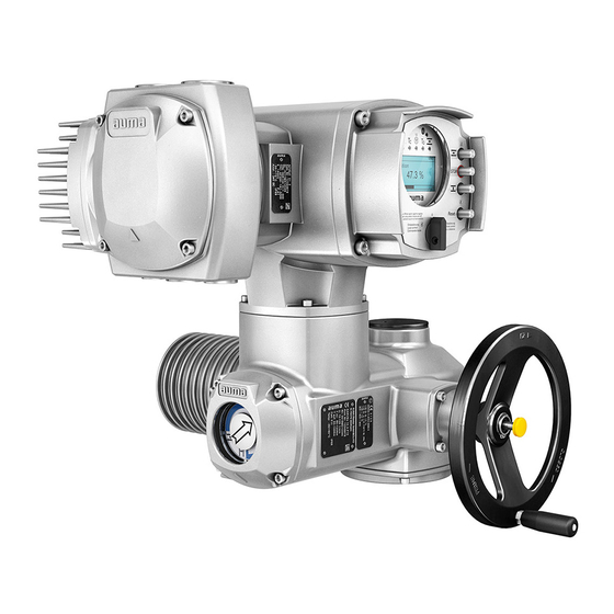
Multi-turn actuators with local controls auma semipact sem 01.1/sem 02.1
Hide thumbs
Also See for SA Series:
- Operating instructions manual (104 pages) ,
- Operation instructions manual (100 pages) ,
- Manual (52 pages)

Related Manuals for AUMA SA Series


Summary of Contents for AUMA SA Series
- Page 1 Multi-turn actuators SA 07.2 SA 16.2 SAR 07.2 SAR 16.2 with local controls AUMA SEMIPACT SEM 01.1/SEM 02.1 Operation instructions Assembly, operation, commissioning...
-
Page 2: Table Of Contents
This document contains information for installation, commissioning, operation and maintenance staff. It is intended to support device installation and commissioning. Reference documents: Reference documents can be downloaded from the Internet (www.auma.com) or ordered directly from AUMA (refer to <Addresses>). Table of contents Page Safety instructions......................... - Page 3 SA 07.2 SA 16.2 / SAR 07.2 SAR 16.2 SEM 01.1/SEM 02.1 Table of contents 5.3. Accessories for electrical connection 5.3.1. Parking frame 5.3.2. DS intermediate frame for double sealing 5.3.3. External earth connection Operation..........................6.1. Manual operation 6.1.1. Engage manual operation 6.1.2.
- Page 4 SEM 01.1/SEM 02.1 Technical data......................... 12.1. Technical data Multi-turn actuators Spare parts..........................13.1. Multi-turn actuators SA 07.2 SA 16.2/SAR 07.2 SAR 16.2 13.2. Local controls AUMA SEMIPACT SEM 01.1/SEM 02.1 Certificates..........................14.1. Declaration of Incorporation and EU Declaration of Conformity Index............................Addresses..........................
-
Page 5: Safety Instructions
Any device modification requires prior written consent of the manufacturer. 1.2. Range of application AUMA multi-turn actuators are designed for the operation of industrial valves, e.g. globe valves, gate valves, butterfly valves, and ball valves. Other applications require explicit (written) confirmation by the manufacturer. -
Page 6: Applications In Ex Zone 22 (Option)
SA 07.2 SA 16.2 / SAR 07.2 SAR 16.2 Safety instructions SEM 01.1/SEM 02.1 Escalators Continuous duty Buried service Continuous submersion (observe enclosure protection) Potentially explosive areas, with the exception of zone 22 Radiation exposed areas in nuclear power plants No liability can be assumed for inappropriate or unintended use. -
Page 7: References And Symbols
SA 07.2 SA 16.2 / SAR 07.2 SAR 16.2 SEM 01.1/SEM 02.1 Safety instructions Indicates a potentially hazardous situation with a medium level of risk. Failure to observe this warning could result in death or serious injury. Indicates a potentially hazardous situation with a low level of risk. Failure to observe this warning could result in minor or moderate injury. -
Page 8: Identification
SA 07.2 SA 16.2 / SAR 07.2 SAR 16.2 Identification SEM 01.1/SEM 02.1 Identification 2.1. Name plate Each device component (actuator, local controls, motor) is equipped with a name plate. Figure 1: Arrangement of name plates Actuator name plate Local controls name plate Motor name plate Additional plate, e.g. - Page 9 Positions 3+4: Year of manufacture = 2016 MD12345 Internal number for unambiguous product identification When registered as authorised user, you may use the AUMA Support App to scan Data Matrix code the Data Matrix code and directly access the order-related product documents without...
-
Page 10: Short Description
Actuator controls are required to operate or process the actuator signals. The AUMA SEMIPACT local control unit is used to operate the actuator from LOCAL. Local controls The SEMIPACT is not considered as actuator controls. The switching elements (push buttons, selector switch) and indication lights must be wired to external controls (e.g. -
Page 11: Transport, Storage And Packaging
SA 07.2 SA 16.2 / SAR 07.2 SAR 16.2 SEM 01.1/SEM 02.1 Transport, storage and packaging Transport, storage and packaging 3.1. Transport For transport to place of installation, use sturdy packaging. Hovering load! Risk of death or serious injury. Do NOT stand below hovering load. Attach ropes or hooks for the purpose of lifting by hoist only to housing and NOT to handwheel. - Page 12 SAR 16.2 Transport, storage and packaging SEM 01.1/SEM 02.1 Indicated weight includes AUMA NORM multi-turn actuator with 3-phase AC motor, electrical con- nection in standard version, output drive type B1 and handwheel. For other output drive types, heed additional weights.
-
Page 13: Storage
SA 07.2 SA 16.2 / SAR 07.2 SAR 16.2 SEM 01.1/SEM 02.1 Transport, storage and packaging Table 5: Weights for output drive type A 07.2 A 16.2 Type designation Flange size [kg] A 07.2 A 10.2 A 14.2 A 16.2 11.7 Table 6: Weights for output drive type AF 07.2... -
Page 14: Assembly
SA 07.2 SA 16.2 / SAR 07.2 SAR 16.2 Assembly SEM 01.1/SEM 02.1 Assembly 4.1. Mounting position The product described in this document can be operated without restriction in any mounting position. 4.2. Handwheel fitting Information For transport reason, handwheels with a diameter 400 mm and larger are supplied separately within the scope of delivery. -
Page 15: 4.3.1.1. Stem Nut: Finish Machining
To adapt the actuators to available output drive types A with flanges F10 and F14 Information (year of manufacture: 2009 and earlier), an adapter is required. The adapter can be ordered from AUMA. 4.3.1.1. Stem nut: finish machining This working step is only required if stem nut is supplied unbored or with pilot bore. -
Page 16: 4.3.1.2. Multi-Turn Actuator (With Output Drive Type A): Mount To Valve
SA 07.2 SA 16.2 / SAR 07.2 SAR 16.2 Assembly SEM 01.1/SEM 02.1 Drill and bore stem nut [1] and cut thread. Information: When fixing in the chuck, make sure stem nut runs true! Clean the machined stem nut [1]. Apply sufficient Lithium soap EP multi-purpose grease to axial needle roller and cage assemblies [2.2] and axial bearing washers [2.1], ensuring that all hollow spaces are filled with grease. -
Page 17: Output Drive Types B
SA 07.2 SA 16.2 / SAR 07.2 SAR 16.2 SEM 01.1/SEM 02.1 Assembly 10. Fasten screws [3] crosswise with a torque according to table. Table 7: Tightening torques for screws Threads Tightening torque [Nm] Strength class A2-80 11. Turn multi-turn actuator with handwheel in direction OPEN until valve flange and output drive A are firmly placed together. -
Page 18: 4.3.2.1. Multi-Turn Actuator With Output Drive Types B: Mount To Valve/Gearbox
SA 07.2 SA 16.2 / SAR 07.2 SAR 16.2 Assembly SEM 01.1/SEM 02.1 Spigot at valve flanges should be loose fit. Information 4.3.2.1. Multi-turn actuator with output drive types B: mount to valve/gearbox Figure 12: Mounting output drive types B Multi-turn actuator Valve/gearbox Valve/gearbox shaft... -
Page 19: Accessories For Assembly
SA 07.2 SA 16.2 / SAR 07.2 SAR 16.2 SEM 01.1/SEM 02.1 Assembly 4.4. Accessories for assembly 4.4.1. Stem protection tube for rising valve stem Figure 13: Assembly of the stem protection tube Protective cap for stem protection tube (fitted) [1]* Option: Protective cap made of steel (screwed) Stem protection tube... -
Page 20: Mounting Positions Of Local Controls
SA 07.2 SA 16.2 / SAR 07.2 SAR 16.2 Assembly SEM 01.1/SEM 02.1 4.5. Mounting positions of local controls The mounting position of the local controls is designed according to the order. If, after mounting the actuator to the valve or the gearbox on site, the local controls are in an unfavourable position, the mounting position can be changed at a later date. -
Page 21: Electrical Connection
It can also be requested from AUMA (state order number, refer to name plate) or downloaded directly from the Internet (http://www.auma.com). Valve damage for connection without controls! Actuators with SEMIPACT local control unit require controls: Connect motor via controls only (reversing contactor circuit). -
Page 22: S/Sh) Electrical Connection (Auma Plug/Socket Connector)
Plug-in electrical connection with screw-type terminals for power and control contacts. Short description S version (standard) with three cable entries. SH version (enlarged) with additional cable entries. For cable connection, remove the AUMA plug/socket connector and the socket carrier from cover. -
Page 23: Terminal Compartment : Open
Brass, tin plated or gold plated (option) For some special motors, the connection of the power terminals (U1, V1, W1, U2, Information V2, W2) is not performed via the AUMA plug/socket connector but via a terminal board directly at the motor. 5.2.1. -
Page 24: Cable Connection
SA 07.2 SA 16.2 / SAR 07.2 SAR 16.2 Electrical connection SEM 01.1/SEM 02.1 Insert cable glands [8] suitable for connecting cables. The enclosure protection IP… stated on the name plate is only ensured if suit- able cable glands are used. Figure 19: Example: Name plate for enclosure protection IP68 Seal unused cable entries [6] with suitable blanking plugs [7]. - Page 25 SA 07.2 SA 16.2 / SAR 07.2 SAR 16.2 SEM 01.1/SEM 02.1 Electrical connection In case of a fault: Hazardous voltage while protective earth conductor is NOT connected! Risk of electric shock. Connect all protective earth conductors. Connect PE connection to external protective earth conductor of connecting cables.
-
Page 26: Terminal Compartment : Close
SA 07.2 SA 16.2 / SAR 07.2 SAR 16.2 Electrical connection SEM 01.1/SEM 02.1 5.2.3. Terminal compartment : close Figure 21: Close terminal compartment Cover (figure shows S version) Screws for cover O-ring Screws for socket carrier Socket carrier Blanking plug Cable gland (not included in scope delivery) Short-circuit due to pinching of cables! Risk of electric shock and functional failures. -
Page 27: Accessories For Electrical Connection
SA 07.2 SA 16.2 / SAR 07.2 SAR 16.2 SEM 01.1/SEM 02.1 Electrical connection 5.3. Accessories for electrical connection 5.3.1. Parking frame Figure 22: Parking frame, example with S plug/socket connector and cover Application Parking frame for safe storage of a disconnected plug or cover. For protection against touching the bare contacts and against environmental influences. -
Page 28: External Earth Connection
SA 07.2 SA 16.2 / SAR 07.2 SAR 16.2 Electrical connection SEM 01.1/SEM 02.1 5.3.3. External earth connection Figure 24: Earth connection for multi-turn actuator External earth connection (terminal clamp) for connection to equipotential Application compensation. Table 11: Terminal cross sections and earth connection tightening torques Conductor type Terminal cross sections Tightening torques... -
Page 29: Operation
SA 07.2 SA 16.2 / SAR 07.2 SAR 16.2 SEM 01.1/SEM 02.1 Operation Operation 6.1. Manual operation For purposes of setting and commissioning, in case of motor failure or power failure, the actuator may be operated manually. Manual operation is engaged by an internal change-over mechanism. -
Page 30: Motor Operation
SA 07.2 SA 16.2 / SAR 07.2 SAR 16.2 Operation SEM 01.1/SEM 02.1 6.2. Motor operation Perform all commissioning settings and the test run prior to motor operation. 6.2.1. Local operation The local operation of the actuator is performed using the push buttons of the local controls. -
Page 31: Indications
SA 07.2 SA 16.2 / SAR 07.2 SAR 16.2 SEM 01.1/SEM 02.1 Indications Indications 7.1. Indication lights — Option — The colours of the 3 indication lights on the local controls are specified in the order. The signal assignment depends on the external wiring. Figure 26: Local controls with indication lights (default signalling) illuminated (green): End position OPEN reached illuminated (red): Fault signal... -
Page 32: Signals (Output Signals)
SA 07.2 SA 16.2 / SAR 07.2 SAR 16.2 Signals (output signals) SEM 01.1/SEM 02.1 Signals (output signals) 8.1. Feedback signals from actuator The switches can be provided as single switches (1 NC and 1 NO), as tandem Information switches (2 NC and 2 NO) or as triple switches (3 NC and 3 NO). The precise version is indicated in the terminal plan or on the order-related technical data sheet. -
Page 33: Commissioning
SA 07.2 SA 16.2 / SAR 07.2 SAR 16.2 SEM 01.1/SEM 02.1 Commissioning Commissioning 9.1. Switch compartment: open The switch compartment must be opened to perform the following settings (options). Loosen screws [2] and remove cover [1] from the switch compartment. If indicator disc [3] is available: Remove indicator disc [3] using a spanner (as lever). -
Page 34: Limit Switching: Set
SA 07.2 SA 16.2 / SAR 07.2 SAR 16.2 Commissioning SEM 01.1/SEM 02.1 Figure 28: Torque measuring heads Torque switching head black in direction CLOSE Torque switching head white in direction OPEN Lock screws Torque dials Loosen both lock screws [3] at the indicator disc. Turn torque dial [4] to set the required torque (1 da Nm = 10 Nm). -
Page 35: End Position Open (White Section): Set
SA 07.2 SA 16.2 / SAR 07.2 SAR 16.2 SEM 01.1/SEM 02.1 Commissioning Turn handwheel by approximately half a turn (overrun) in the opposite direction. Press down and turn setting spindle [1] with screw driver in direction of the arrow and observe the pointer [2]: While a ratchet click is felt and heard, the pointer [2] moves 90°... -
Page 36: Running Direction Close (Black Section): Set
SA 07.2 SA 16.2 / SAR 07.2 SAR 16.2 Commissioning SEM 01.1/SEM 02.1 Figure 30: Setting elements for limit switching Black section: Setting spindle: Running direction CLOSE Pointer: Running direction CLOSE Mark: Intermediate position CLOSED is set White section: Setting spindle: Running direction OPEN Pointer: Running direction OPEN Mark: Intermediate position OPEN is set Information... -
Page 37: Test Run
SA 07.2 SA 16.2 / SAR 07.2 SAR 16.2 SEM 01.1/SEM 02.1 Commissioning As soon as the pointer [5] moves to mark [6]: Stop turning and release setting spindle. The intermediate position setting in running direction OPEN is complete. If you override the tripping point inadvertently (ratchet click is heard after the pointer has snapped): Continue turning the setting spindle in the same direction and repeat setting process. -
Page 38: Limit Switching: Check
SA 07.2 SA 16.2 / SAR 07.2 SAR 16.2 Commissioning SEM 01.1/SEM 02.1 Without mechanical position indication: Unscrew threaded plug [1] and seal [2] or protective cap for stem protection tube [4] and observe direction of rotation at hollow shaft [3] or the stem [5]. -
Page 39: Measuring Range: Set
SA 07.2 SA 16.2 / SAR 07.2 SAR 16.2 SEM 01.1/SEM 02.1 Commissioning Technical data Table 14: EWG 01.1 Data 3-wire and 4-wire systems 2-wire system Output current I 20 mA, 4 20 mA 20 mA Power supply U 24 V DC (18 32 V) 24 V DC (18 32 V) -
Page 40: Current Values: Adjust
SA 07.2 SA 16.2 / SAR 07.2 SAR 16.2 Commissioning SEM 01.1/SEM 02.1 Information Both measuring ranges 0/4 20 mA and 20 0/4 mA (inverse operation) can be set. During setting process, the measuring range (normal or inverse operation) is assigned to the end positions by push button S1/S2 assignment. -
Page 41: Led End Position Signalling: Switch On/Off
SA 07.2 SA 16.2 / SAR 07.2 SAR 16.2 SEM 01.1/SEM 02.1 Commissioning Operate valve in desired end position (OPEN/CLOSED). Reduce current value: Press push button [S1] (the current is reduced by 0.02 mA every time the push button is pressed) Increase current value: Press push button [S2] (the current is increased by 0.02 mA every time the push button is... -
Page 42: Electronic Position Transmitter Rwg
SA 07.2 SA 16.2 / SAR 07.2 SAR 16.2 Commissioning SEM 01.1/SEM 02.1 Move valve to end position CLOSED. Turn potentiometer [1] clockwise to the stop. End position CLOSED corresponds to 0 % End position OPEN corresponds to 100 % Turn potentiometer [1] slightly in opposite direction. -
Page 43: Mechanical Position Indicator: Set
SA 07.2 SA 16.2 / SAR 07.2 SAR 16.2 SEM 01.1/SEM 02.1 Commissioning Move valve to end position CLOSED. Connect measuring equipment for 0 20 mA to measuring points [4] and [5]. If no value can be measured: Check whether external load is connected to customer connection XK (for standard wiring: terminals 23/24). -
Page 44: Switch Compartment: Close
SA 07.2 SA 16.2 / SAR 07.2 SAR 16.2 Commissioning SEM 01.1/SEM 02.1 9.10. Switch compartment: close Danger of corrosion due to damage to paint finish! Touch up damage to paint finish after work on the device. Clean sealing faces of housing and cover. Check whether O-ring [3] is in good condition, replace if damaged. -
Page 45: Corrective Action
SA 07.2 SA 16.2 / SAR 07.2 SAR 16.2 SEM 01.1/SEM 02.1 Corrective action Corrective action 10.1. Faults during operation/commissioning Table 18: Faults during operation/commissioning Fault Description/cause Remedy Mechanical position indicator cannot Reduction gearing is not suitable for turns/stroke Exchange reduction gearing. be set. - Page 46 SA 07.2 SA 16.2 / SAR 07.2 SAR 16.2 Corrective action SEM 01.1/SEM 02.1 Overload, running time exceeded, max. number of starts exceeded, ambient Possible causes temperature is too high. Check cause, eliminate if possible. Remedy...
-
Page 47: Servicing And Maintenance
Therefore, we recommend contacting our service. Only perform servicing and maintenance tasks when the device is switched off. AUMA AUMA offers extensive service such as servicing and maintenance as well as Service & Support customer product training. For the relevant contact addresses, please refer to <Addresses>... -
Page 48: Disposal And Recycling
SA 07.2 SA 16.2 / SAR 07.2 SAR 16.2 Servicing and maintenance SEM 01.1/SEM 02.1 Grease change is performed during maintenance Generally after 4 to 6 years for modulating duty. Generally after 6 to 8 years if operated frequently (open-close duty). Generally after 10 to 12 years if operated rarely (open-close duty). -
Page 49: Technical Data
Information on the customer-specific version, refer to the order-related data sheet. The technical data sheet can be downloaded from the Internet in both German and English at ht- tp://www.auma.com (please state the order number). 12.1. Technical data Multi-turn actuators Features and functions... - Page 50 SA 07.2 SA 16.2 / SAR 07.2 SAR 16.2 Technical data SEM 01.1/SEM 02.1 Features and functions Valve attachment Standard: B1 according to EN ISO 5210 Option: A, B2, B3, B4 according to EN ISO 5210 A, B, D, E according to DIN 3210 C according to DIN 3338 Special valve attachments: AF, AK, AG, B3D, ED, DD, IB1, IB3 A prepared for permanent lubrication of stem...
- Page 51 Resistant to vibration during start-up or for failures of the plant. However, a fatigue strength may not be derived from this. Indications apply to actuators with AUMA 3-phase AC motor and AUMA plug/socket connector. They are not valid in combination with gearboxes.
- Page 52 AUMA silver-grey (similar to RAL 7037) Option: Other colours are possible on request. Lifetime AUMA multi-turn actuators meet or exceed the lifetime requirements of EN 15714-2. For further details, please contact AUMA Noise level < 72 dB (A) Further information...
-
Page 53: Spare Parts
SA 07.2 SA 16.2 / SAR 07.2 SAR 16.2 SEM 01.1/SEM 02.1 Spare parts Spare parts 13.1. Multi-turn actuators SA 07.2 SA 16.2/SAR 07.2 SAR 16.2... - Page 54 SEM 01.1/SEM 02.1 Please state device type and our order number (see name plate) when ordering spare parts. Only original AUMA spare parts should be used. Failure to use original spare parts voids the warranty and exempts AUMA from any liability. Representation of spare parts may slightly vary from actual delivery.
-
Page 55: Local Controls Auma Semipact Sem 01.1/Sem
SA 07.2 SA 16.2 / SAR 07.2 SAR 16.2 SEM 01.1/SEM 02.1 Spare parts 13.2. Local controls AUMA SEMIPACT SEM 01.1/SEM 02.1... - Page 56 SEM 01.1/SEM 02.1 Please state device type and our order number (see name plate) when ordering spare parts. Only original AUMA spare parts should be used. Failure to use original spare parts voids the warranty and exempts AUMA from any liability. Representation of spare parts may slightly vary from actual delivery.
-
Page 57: Certificates
SAR 16.2 SEM 01.1/SEM 02.1 Certificates Certificates Certificates are valid as from the indicated date of issue. Subject to changes without Information notice. The latest versions are available for download at http://www.auma.com. 14.1. Declaration of Incorporation and EU Declaration of Conformity... - Page 58 SA 07.2 SA 16.2 / SAR 07.2 SAR 16.2 SEM 01.1/SEM 02.1...
- Page 59 SA 07.2 SA 16.2 / SAR 07.2 SAR 16.2 SEM 01.1/SEM 02.1...
-
Page 60: Index
SA 07.2 SA 16.2 / SAR 07.2 SAR 16.2 Index SEM 01.1/SEM 02.1 Index Identification Indication lights Indications Accessories (electrical con- Indicator disc nection) Indicator mark Accessories for assembly Inspection certificate Actuator controls wiring dia- Intermediate frame gram Intermediate positions Actuator operation from re- Inverse operation (0/20 mote... - Page 61 SA 07.2 SA 16.2 / SAR 07.2 SAR 16.2 SEM 01.1/SEM 02.1 Index Range of application Recycling Remote actuator operation Running indication Safety instructions Safety instructions/warnings Serial number 8, 9, 9 Service Servicing Short-circuit protection Signals Signals from local controls Size Spare parts Speed...
-
Page 62: Addresses
AUMA Finland Oy AUMA Polska Sp. z o.o. FI 02230 Espoo PL 41-219 Sosnowiec Tel +358 9 5840 22 Tel +48 32 783 52 00 AUMA Riester GmbH & Co. KG auma@auma.fi biuro@auma.com.pl www.auma.fi www.auma.com.pl Location Muellheim DE 79373 Muellheim AUMA France S.A.R.L. - Page 63 AUMA worldwide AUMA South Africa (Pty) Ltd. Mikuni (B) Sdn. Bhd. Mustafa Sultan Science & Industry Co LLC ZA 1560 Springs BN KA1189 Kuala Belait OM Ruwi Tel +27 11 3632880 Tel + 673 3331269 / 3331272 Tel +968 24 636036 aumasa@mweb.co.za...
- Page 64 AUMA Riester GmbH & Co. KG P.O. Box 1362 DE 79373 Muellheim Tel +49 7631 809 - 0 Fax +49 7631 809 - 1250 info@auma.com www.auma.com Y005.028/003/en/1.17 For detailed information on AUMA products, refer to the Internet: www.auma.com...
Need help?
Do you have a question about the SA Series and is the answer not in the manual?
Questions and answers
Здравствуйте! Подскажите есть у Вас ТУ на электропривод auma sa 07.6.