AUMA SA 07.2 Operation Instructions Manual
Multi-turn actuators with actuator controls
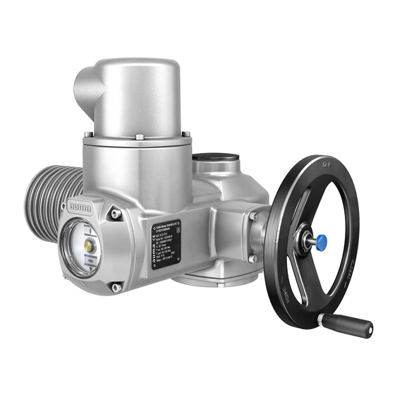
auma matic basic amb 01.1/amb02.1
Hide thumbs
Also See for SA 07.2:
- Operation manual (108 pages) ,
- Operation instructions manual (96 pages) ,
- Manual (24 pages)

Related Manuals for AUMA SA 07.2


Summary of Contents for AUMA SA 07.2
- Page 1 Multi-turn actuators SA 07.2 SA 16.2/SAR 07.2 SAR 16.2 with actuator controls AUMA MATIC BASIC AMB 01.1/AMB02.1 Operation instructions Assembly, operation, commissioning...
-
Page 2: Table Of Contents
This document contains information for installation, commissioning, operation and maintenance staff. It is intended to support device installation and commissioning. Reference documents: Reference documents can be downloaded from the Internet (www.auma.com) or ordered directly from AUMA (refer to <Addresses>). Table of contents Page Safety instructions......................... - Page 3 SA 07.2 SA 16.2/SAR 07.2 SAR 16.2 AMB 01.1/AMB02.1 Table of contents 5.3. Accessories for electrical connection 5.3.1. Parking frame 5.3.2. Protection cover 5.3.3. Double sealed intermediate frame 5.3.4. External earth connection Operation..........................6.1. Manual operation 6.1.1. Manual operation: engage 6.1.2.
- Page 4 Technical data Multi-turn actuators 13.2. Technical data Actuator controls Spare parts..........................14.1. Spare parts list SA 07.2 SA 16.2/SAR 07.2 SAR 16.2 14.2. Actuator controls AUMA MATIC BASIC AMB 01.1/AMB 02.1 Certificates..........................15.1. Declaration of Incorporation and EC Declaration of Conformity Index............................Addresses..........................
-
Page 5: Safety Instructions
Any device modification requires prior consent of the manufacturer. 1.2. Range of application AUMA multi-turn actuators are designed for the operation of industrial valves, e.g. globe valves, gate valves, butterfly valves, and ball valves. Other applications require explicit (written) confirmation by the manufacturer. -
Page 6: Applications In Ex Zone 22 (Option)
SA 07.2 SA 16.2/SAR 07.2 SAR 16.2 Safety instructions AMB 01.1/AMB02.1 Escalators Continuous duty Buried service Continuous submersion (observe enclosure protection) Potentially explosive areas, with the exception of zone 22 Radiation exposed areas in nuclear power plants No liability can be assumed for inappropriate or unintended use. -
Page 7: References And Symbols
SA 07.2 SA 16.2/SAR 07.2 SAR 16.2 AMB 01.1/AMB02.1 Safety instructions Indicates a potentially hazardous situation with a medium level of risk. Failure to observe this warning could result in death or serious injury. Indicates a potentially hazardous situation with a low level of risk. Failure to observe this warning may result in minor or moderate injury. -
Page 8: Identification
SA 07.2 SA 16.2/SAR 07.2 SAR 16.2 Identification AMB 01.1/AMB02.1 Identification 2.1. Name plate Each device component (actuator, controls, motor) is equipped with a name plate. Figure 1: Arrangement of name plates Actuator name plate Actuator controls name plate Motor name plate Additional plate, e.g. - Page 9 Type and size These instructions apply to the following devices types and sizes: SA 07.2, 07.6, 10.2, 14.2, 14.6, 16.2 = multi-turn actuators for open-close duty SAR 07.2, 07.6, 10.2, 14.2, 14.6, 16.2 = multi-turn actuators for modulating duty AMB 01.1 = AUMA MATIC BASIC actuator controls...
-
Page 10: Short Description
The rated power (nominal power) of the actuator motor is indicated in kW on the motor name plate. For the assignment of the AUMA power classes to the nominal power of the motor types, refer to the separate electrical data sheets. -
Page 11: Transport, Storage And Packaging
SA 07.2 SA 16.2/SAR 07.2 SAR 16.2 AMB 01.1/AMB02.1 Transport, storage and packaging Transport, storage and packaging 3.1. Transport For transport to place of installation, use sturdy packaging. Hovering load! Risk of death or serious injury. Do NOT stand below hovering load. -
Page 12: Assembly
SAR 16.2 Assembly AMB 01.1/AMB02.1 Assembly 4.1. Mounting position AUMA actuators and actuator controls can be operated without restriction in any mounting position. 4.2. Handwheel fitting Information For transport purposes, handwheels from a diameter of 400 mm are supplied separ- ately. -
Page 13: Multi-Turn Actuator (With Output Drive Types B1 B4 Or E): Mount To Valve/Gearbox
SA 07.2 SA 16.2/SAR 07.2 SAR 16.2 AMB 01.1/AMB02.1 Assembly Figure 7: Output drive Output drive types B, B1 B4, E and C Output drive sleeve/output drive plug sleve with bore and keyway Circlip Information Spigot at flanges should be loose fit. -
Page 14: 4.3.2.1. Stem Nut: Finish Machining
SA 07.2 SA 16.2/SAR 07.2 SAR 16.2 Assembly AMB 01.1/AMB02.1 4.3.2.1. Stem nut: finish machining This working step is only required if stem nut is supplied unbored or with pilot bore. Figure 8: Design of output drive type A Stem nut Bearing [2.1] Bearing race... -
Page 15: 4.3.2.2. Multi-Turn Actuator (With Output Drive Type A): Mount To Valve
SA 07.2 SA 16.2/SAR 07.2 SAR 16.2 AMB 01.1/AMB02.1 Assembly 4.3.2.2. Multi-turn actuator (with output drive type A): mount to valve Figure 9: Assembly with output drive type A Valve stem Output drive type A Screws to actuator Valve flange... -
Page 16: Accessories For Assembly
SA 07.2 SA 16.2/SAR 07.2 SAR 16.2 Assembly AMB 01.1/AMB02.1 4.4. Accessories for assembly 4.4.1. Stem protection tube for rising valve stem — Option — Figure 10: Assembly of the stem protection tube Cap for stem protection tube Stem protection tube Sealing ring Seal thread with hemp, Teflon tape, or thread sealing material. -
Page 17: Mounting Positions: Modify
SA 07.2 SA 16.2/SAR 07.2 SAR 16.2 AMB 01.1/AMB02.1 Assembly Figure 12: Mounting positions C and D 4.5.1. Mounting positions: modify Hazardous voltage! Risk of electric shock. Disconnect device from the mains before opening. Loosen screws and remove the local controls. -
Page 18: Electrical Connection
The pertaining wiring diagram/terminal plan (both in German and English) is attached plan to the device in a weather-proof bag, together with these operation instructions. It can also be requested from AUMA (state order number, refer to name plate) or downloaded directly from the Internet (http://www.auma.com). Protection on site For short-circuit protection and for disconnecting the actuator from the mains, fuses and disconnect switches have to be provided by the customer. -
Page 19: Connection With Auma Plug/Socket Connector
Control contacts (1 to 50): max. 2.5 mm² Information For some special motors, the connection of the power terminals (U1, V1, W1, U2, V2, W2) is not performed via the AUMA plug/socket connector but via a terminal board at the motor. 5.2.1. -
Page 20: Cable Connection
SA 07.2 SA 16.2/SAR 07.2 SAR 16.2 Electrical connection AMB 01.1/AMB02.1 Hazardous voltage! Risk of electric shock. Disconnect device from the mains before opening. Loosen screws [2] and remove cover [1]. Loosen screws [4] and remove socket carrier [5] from cover [1]. - Page 21 SA 07.2 SA 16.2/SAR 07.2 SAR 16.2 AMB 01.1/AMB02.1 Electrical connection In case of a fault: Hazardous voltage while protective earth conductor is NOT connected! Risk of electric shock. Connect all protective earth conductors. Connect PE connection to external protective earth conductor of connecting cables.
-
Page 22: Terminal Compartment: Close
SA 07.2 SA 16.2/SAR 07.2 SAR 16.2 Electrical connection AMB 01.1/AMB02.1 5.2.3. Terminal compartment: close Figure 17: Example: Version S Cover Screws for cover O-ring Screws for socket carrier Socket carrier Cable entry Blanking plugs Cable gland (not included in delivery) Short-circuit due to pinching of cables! Risk of electric shock and functional failures. -
Page 23: Protection Cover
SA 07.2 SA 16.2/SAR 07.2 SAR 16.2 AMB 01.1/AMB02.1 Electrical connection Figure 18: Parking frame 5.3.2. Protection cover — Option — Protection cover for plug compartment when plug is removed. Application The open terminal compartment can be closed using a protective cover (not illustrated). -
Page 24: Operation
SA 07.2 SA 16.2/SAR 07.2 SAR 16.2 Operation AMB 01.1/AMB02.1 Operation 6.1. Manual operation For purposes of setting and commissioning, in case of motor failure or power failure, the actuator may be operated manually. Manual operation is engaged by an internal change-over mechanism. -
Page 25: Actuator Operation From Remote
SA 07.2 SA 16.2/SAR 07.2 SAR 16.2 AMB 01.1/AMB02.1 Operation Figure 20: Local controls Push button for operation command in direction OPEN Push button Stop Push button for operation command in direction CLOSE Selector switch Hot surfaces, e.g. possibly caused by high ambient temperatures or strong... -
Page 26: Indications
SA 07.2 SA 16.2/SAR 07.2 SAR 16.2 Indications AMB 01.1/AMB02.1 Indications 7.1. Indication lights Figure 21: Local controls with indication lights illuminated (green): End position OPEN reached illuminated (red): Fault signal (option) illuminated (yellow): End position CLOSED reached The fault signal (red indication light) indicates the following events: Fault signal (option) Torque fault: The set torque was exceeded before reaching an end position. -
Page 27: Signals
SA 07.2 SA 16.2/SAR 07.2 SAR 16.2 AMB 01.1/AMB02.1 Signals Signals 8.1. Feedback signals (binary) Information The switches can be provided as single switches (1NC and 1 NO), as tandem switches (2 NC and 2 NO) or as triple switches (3 NC and 3 NO). The precise version is indicated in the terminal plan or on the order-related technical data sheet. -
Page 28: Commissioning (Basic Settings)
SA 07.2 SA 16.2/SAR 07.2 SAR 16.2 Commissioning (basic settings) AMB 01.1/AMB02.1 Commissioning (basic settings) Set selector switch to position 0 (OFF). Information: The selector switch is not a mains switch. When positioned to 0 (OFF), the actuator cannot be operated. The controls' power supply is maintained. -
Page 29: Limit Switching: Set
SA 07.2 SA 16.2/SAR 07.2 SAR 16.2 AMB 01.1/AMB02.1 Commissioning (basic settings) Valve damage due to excessive tripping torque limit setting! The tripping torque must suit the valve. Only change the setting with the consent of the valve manufacturer. Figure 23: Torque measuring heads... -
Page 30: End Position Closed (Black Section): Set
SA 07.2 SA 16.2/SAR 07.2 SAR 16.2 Commissioning (basic settings) AMB 01.1/AMB02.1 9.3.1. End position CLOSED (black section): set Engage manual operation. Turn handwheel clockwise until valve is closed. Turn handwheel by approximately half a turn (overrun) in the opposite direction. -
Page 31: Running Direction Close (Black Section): Set
SA 07.2 SA 16.2/SAR 07.2 SAR 16.2 AMB 01.1/AMB02.1 Commissioning (basic settings) Figure 25: Setting elements for limit switching Black section: Setting spindle: Running direction CLOSE Pointer: Running direction CLOSE Mark: Intermediate position CLOSED is set White section: Setting spindle: Running direction OPEN... -
Page 32: Test Run
SA 07.2 SA 16.2/SAR 07.2 SAR 16.2 Commissioning (basic settings) AMB 01.1/AMB02.1 If you override the tripping point inadvertently (ratchet click is heard after the pointer has snapped): Continue turning the setting spindle in the same direction and repeat setting process. -
Page 33: Limit Switching: Check
SA 07.2 SA 16.2/SAR 07.2 SAR 16.2 AMB 01.1/AMB02.1 Commissioning (basic settings) Without the indicator disc: Unscrew threaded plug [1] and seal [2] or cap for stem protection tube [4] and observe direction of rotation at hollow shaft [3] or the stem [5]. -
Page 34: Measuring Range: Set
SA 07.2 SA 16.2/SAR 07.2 SAR 16.2 Commissioning (basic settings) AMB 01.1/AMB02.1 Technical data Table 7: EWG 01.1 Data 3-wire or 4-wire system 2-wire system Output current I 20 mA, 4 20 mA 20 mA Power supply U 24 V DC (18... -
Page 35: Current Values: Adjust
SA 07.2 SA 16.2/SAR 07.2 SAR 16.2 AMB 01.1/AMB02.1 Commissioning (basic settings) Information Both measuring ranges 0/4 20 mA and 20 0/4 mA (inverse operation) can be set. During setting process, the measuring range (normal or inverse operation) is assigned to the end positions by push button S1/S2 assignment. -
Page 36: Led End Position Signalling: Switch On/Off
SA 07.2 SA 16.2/SAR 07.2 SAR 16.2 Commissioning (basic settings) AMB 01.1/AMB02.1 Operate valve in desired end position (OPEN/CLOSED). Reduce current value: Press push button [S1] (the current is reduced by 0.02 mA every time the push button is pressed) Increase current value: Press push button [S2] (the current is increased by 0.02 mA every time the push button is... -
Page 37: Electronic Position Transmitter Rwg
SA 07.2 SA 16.2/SAR 07.2 SAR 16.2 AMB 01.1/AMB02.1 Commissioning (basic settings) Turn potentiometer [1] clockwise to the stop. End position CLOSED corresponds to 0 % End position OPEN corresponds to 100 % Turn potentiometer [1] slightly in opposite direction. -
Page 38: Mechanical Position Indicator: Set
SA 07.2 SA 16.2/SAR 07.2 SAR 16.2 Commissioning (basic settings) AMB 01.1/AMB02.1 Connect measuring equipment for 0 20 mA to measuring points [4] and [5]. If no value can be measured: Check whether external load is connected to customer connection XK (for standard wiring: terminals 23/24). -
Page 39: Switch Compartment: Close
SA 07.2 SA 16.2/SAR 07.2 SAR 16.2 AMB 01.1/AMB02.1 Commissioning (basic settings) 9.10. Switch compartment: close Danger of corrosion due to damage to paint finish! Touch up damage to paint finish after work on the device. Clean sealing faces of housing and cover. -
Page 40: Commissioning Controls Settings
SA 07.2 SA 16.2/SAR 07.2 SAR 16.2 Commissioning controls settings AMB 01.1/AMB02.1 Commissioning controls settings The controls are set in the factory according to the order. The settings only have to be changed if the device is used for applications other than those specified in the order. -
Page 41: Push-To-Run Operation Or Self-Retaining: Set
SA 07.2 SA 16.2/SAR 07.2 SAR 16.2 AMB 01.1/AMB02.1 Commissioning controls settings Set type of seating via toggle switch [S9]. Figure 30: Signal and control board [S9] Toggle switch in position = limit seating in position = torque seating 10.3. -
Page 42: Local Controls: Mount
SA 07.2 SA 16.2/SAR 07.2 SAR 16.2 Commissioning controls settings AMB 01.1/AMB02.1 Loosen all 3 screws [2] on the signal and control board [1] and remove board. Information: Make sure not to disconnect the jumpers. Figure 32: Remove signal and control board Set push-to-run operation or self-retaining via red jumper on wiring board. -
Page 43: Controls: Open
(terminals XK) have been entered. In case of sub- sequent change of the setting (rewiring of the jumpers), the wiring diagram provided will no longer correspond to the changed settings. For this reason, setting changes may exclusively be performed by the AUMA service. -
Page 44: Emergency Command (Emergency - Open/Emergency - Close): Set
SA 07.2 SA 16.2/SAR 07.2 SAR 16.2 Commissioning controls settings AMB 01.1/AMB02.1 Figure 35: Relay board; left: version B02, right: version B04 Table 11: Feedback signals setting Function Signal at termin- Link (Signal at terminal XK … active, if function matches) -
Page 45: Controls: Close
(rewiring of the jumper), the wiring diagram will no longer correspond to the changed settings. For this reason, setting changes may exclusively be performed by the AUMA service. Figure 36: Relay board Table 12: EMERGENCY command setting... - Page 46 SA 07.2 SA 16.2/SAR 07.2 SAR 16.2 Commissioning controls settings AMB 01.1/AMB02.1 Apply a thin film of non-acidic grease (e.g. petroleum jelly) to the O-ring and insert it correctly. Place cover [1] on switch compartment. Fasten screws [2] evenly crosswise.
-
Page 47: Corrective Action
SA 07.2 SA 16.2/SAR 07.2 SAR 16.2 AMB 01.1/AMB02.1 Corrective action Corrective action 11.1. Faults during commissioning Table 13: Faults during commissioning Fault Description/cause Remedy Mechanical position indicator Reduction gearing is not suitable for Exchange reduction gearing. cannot be set. - Page 48 SA 07.2 SA 16.2/SAR 07.2 SAR 16.2 Corrective action AMB 01.1/AMB02.1 Figure 37: Access to fuses Local controls Signal and control board Power supply unit Primary fuses on power supply unit F1/F2 G fuse F1/F2 AUMA art. no. Size 6.3 x 32 mm Reversing contactors 1 A T;...
-
Page 49: Motor Protection (Thermal Monitoring)
SA 07.2 SA 16.2/SAR 07.2 SAR 16.2 AMB 01.1/AMB02.1 Corrective action 11.2.2. Motor protection (thermal monitoring) In order to protect against overheating and impermissibly high surface temperatures at the actuator, thermoswitches are embedded in the motor winding.The thermoswitch is tripped as soon as the max. permissible winding temperature has been reached. -
Page 50: Servicing And Maintenance
Only perform servicing and maintenance tasks when the device is switched off. AUMA AUMA offer extensive service such as servicing and maintenance as well as customer Service & Support product training. For the relevant contact addresses, please refer to <Addresses>... -
Page 51: Disposal And Recycling
SA 07.2 SA 16.2/SAR 07.2 SAR 16.2 AMB 01.1/AMB02.1 Servicing and maintenance Grease change is performed during maintenance Generally after 4 to 6 years for modulating duty. Generally after 6 to 8 years if operated frequently (open-close duty). Generally after 10 to 12 years if operated rarely (open-close duty). -
Page 52: Technical Data
The following technical data includes standard and optional features. For detailed information on the customer-specific version, refer to the order-related data sheet. The technical data sheet can be downloaded from the Internet at www.auma.com in both German and English (please state the order number). - Page 53 SA 07.2 SA 16.2/SAR 07.2 SAR 16.2 AMB 01.1/AMB02.1 Technical data Electromechanical control unit Limit switching Counter gear mechanism for end positions OPEN and CLOSED Turns per stroke: 2 to 500 (standard) or 2 to 5,000 (option) Standard: Single switches (1 NC and 1 NO) for each end position, not galvanically isolated...
- Page 54 Resistant to vibration during start-up or for failures of the plant. However, a fatigue strength may not be derived from this. Valid for multi-turn actuators in version AUMA NORM (with AUMA plug/socket connector, without actuator controls). Not valid in combination with gearboxes.
-
Page 55: Technical Data Actuator Controls
Reversing contactors (mechanically and electrically interlocked) for AUMA power class A3 Reversing contactors are designed for a lifetime of 2 million starts. For the assignment of AUMA power classes, please refer to Electrical data Multi-turn actuat- ors/Part-turn actuators. Control Standard:... - Page 56 Resistant to vibration during start-up or for failures of the plant. However, a fatigue strength may not be derived from this. Valid for multi-turn actuators in version AUMA NORM (with AUMA plug/socket connector, without actuator controls). Not valid in combination with gearboxes.
- Page 57 Two-component iron-mica combination Colour Standard: AUMA silver-grey (similar to RAL 7037) Option: Other colours available on request Further information Weight Approx. 7 kg (with AUMA plug/socket connector) EU Directives Electromagnetic Compatibility (EMC): (2004/108/EC) Low Voltage Directive: (2006/95/EC) Machinery Directive: (2006/42/EC)
-
Page 58: Spare Parts
SA 07.2 SA 16.2/SAR 07.2 SAR 16.2 Spare parts AMB 01.1/AMB02.1 Spare parts 14.1. Spare parts list SA 07.2 SA 16.2/SAR 07.2 SAR 16.2... - Page 59 Information: Please state device type and our order number (see name plate) when ordering spare parts. Only original AUMA spare parts should be used. Failure to use original spare parts voids the warranty and exempts AUMA from any liability. Delivered spare parts may slightly vary from the representation in these instructions.
-
Page 60: Actuator Controls Auma Matic Basic Amb 01.1/Amb
SA 07.2 SA 16.2/SAR 07.2 SAR 16.2 Spare parts AMB 01.1/AMB02.1 14.2. Actuator controls AUMA MATIC BASIC AMB 01.1/AMB 02.1... - Page 61 Information: Please state device type and our order number (see name plate) when ordering spare parts. Only original AUMA spare parts should be used. Failure to use original spare parts voids the warranty and exempts AUMA from any liability. Delivered spare parts may slightly vary from the representation in these instructions.
-
Page 62: Certificates
SA 07.2 SA 16.2/SAR 07.2 SAR 16.2 Certificates AMB 01.1/AMB02.1 Certificates 15.1. Declaration of Incorporation and EC Declaration of Conformity... -
Page 63: Index
SA 07.2 SA 16.2/SAR 07.2 SAR 16.2 AMB 01.1/AMB02.1 Index Index Identification Indication lights Indications Accessories (electrical con- Indicator disc 26 , 38 nection) Input current Accessories for assembly Input signal Actuator controls terminal Inspection record plan Intermediate frame Actuator operation from re-... - Page 64 SA 07.2 SA 16.2/SAR 07.2 SAR 16.2 Index AMB 01.1/AMB02.1 Range of application Recycling Remote actuator operation Running indication 26 , 27 Safety instructions Safety instructions/warnings Self-retaining: set Serial number 8 , 9 , 9 Service Servicing Short-circuit protection Signals...
-
Page 65: Addresses
IBEROPLAN S.A. AUMA Polska Sp. z o.o. ES 28027 Madrid PL 41-219 Sosnowiec Tel +34 91 3717130 Tel +48 32 783 52 00 AUMA Riester GmbH & Co. KG iberoplan@iberoplan.com biuro@auma.com.pl www.auma.com.pl Plant Müllheim AUMA Finland Oy DE 79373 Müllheim FI 02230 Espoo AUMA-LUSA Representative Office, Lda. - Page 66 AUMA worldwide AUMA South Africa (Pty) Ltd. Mikuni (B) Sdn. Bhd. Mustafa Sultan Science & Industry Co LLC ZA 1560 Springs BN KA1189 Kuala Belait OM Ruwi Tel +27 11 3632880 Tel + 673 3331269 / 3331272 Tel +968 24 636036 aumasa@mweb.co.za...
- Page 67 AUMA worldwide...
- Page 68 AUMA Riester GmbH & Co. KG P.O.Box 1362 DE 79373 Muellheim Tel +49 7631 809 - 0 Fax +49 7631 809 - 1250 riester@auma.com www.auma.com Y005.411/003/en/1.15 For detailed information on AUMA products, refer to the Internet: www.auma.com...
Need help?
Do you have a question about the SA 07.2 and is the answer not in the manual?
Questions and answers