Citizen CD-S500 Series Service Manual
Dot matrix printer
Hide thumbs
Also See for CD-S500 Series:
- Command reference manual (111 pages) ,
- User manual (52 pages) ,
- User manual (52 pages)
Table of Contents
Advertisement
Quick Links
Download this manual
See also:
User Manual
Advertisement
Table of Contents
Troubleshooting

Related Manuals for Citizen CD-S500 Series


Summary of Contents for Citizen CD-S500 Series
-
Page 1: Service Manual
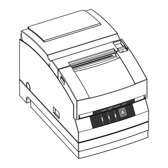
DOT MATRIX PRINTER CD-S500 Series Service Manual Rev. 1 (2005. 05) NJ74905-01F... - Page 2 CD-S500 Series Introduction This manual is intended for in-field service personnel and explains maintenance procedures for Citizen Dot Matrix Printer CD-S500 series. Read and understand the contents described in this manual for appropriate maintenance. Features This printer is a dot matrix printer developed for use with various kinds of data communication terminals, POS terminals, and kitchen printers.
- Page 3 CD-S500 Series Explanation of Models Models in this series are identified by the following model naming method. Model number: CD-S Model name 500: Standard model 501: Auto cutter model 503: Rewinder model Power source type A: External AC adapter type...
-
Page 4: Table Of Contents
CD-S500 Series Contents Chapter 1 SAFETY INSTRUCTIONS Conventions for Warning and Caution ................... 1-1 Precautions in Handling ......................1-1 Precautions in Storage ......................1-1 Precautions in Maintenance ....................1-2 Chapter 2 SPECIFICATIONS General Specification ......................2-1 External Dimensions ......................2-3... - Page 5 CD-S500 Series Disassembly and Assembly of the Mechanism Unit ............3-10 3-7-1 Disassembly and Assembly of Standard Model ............ 3-10 ♦ Removing the SA Rear Cover Switch and the Spring for Lever ......3-10 ♦ Precaution when Mounting the Rear Cover Switch ........... 3-11 ♦...
- Page 6 CD-S500 Series ♦ Removing the Paper Guide ................3-28 ♦ Removing the Platen ..................3-28 ♦ Removing Armature Switch 2 ................3-29 ♦ Removing the SA1 PF shaft ................3-29 ♦ Precaution when Mounting Armature Switch 2 ..........3-29 ♦...
- Page 7 CD-S500 Series 3-13 Oiling ............................ 3-42 3-14 Setting the Paper Near End Sensor ..................3-43 3-15 Adjusting the Head Gap ....................... 3-44 Chapter 4 PARTS LIST Mechanical Parts List ......................4-1 4-1-1 Drawing No. 1 Parts List & Location for AC Adapter Case ........4-1 4-1-2 Drawing No.
- Page 8 CD-S500 Series SA, OPE-PANE PCB ......................5-12 SA, SERIAL I/F PCB (MM) ....................5-13 SA, SERIAL I/F PCB (INCH) ....................5-14 SA, PARALLEL I/F PCB ...................... 5-15 SA, PNE SENS PCB ......................5-16 SA, BM SENS PCB ......................5-17 Chapter 6 TROUBLESHOOTING Troubleshooting List ......................
-
Page 9: Safety Instructions
Chapter 1 SAFETY INSTRUCTIONS... -
Page 10: Conventions For Warning And Caution
If a paper type other than the recommended paper is used, printing quality or service life may not be guaranteed. Also, be sure to use the paper of the specified width. Use a ribbon cassette for the CD-S500 series. If any other ribbon cassette is used, CAUTION some problem, such as print head wire malfunction or poor printing quality, may occur. -
Page 11: Precautions In Maintenance
CD-S500 Series Precautions in Maintenance • When performing disassembly, assembly or adjustment, provide static protection and release static electricity from your body to protect printed circuit boards, etc. from damage due to static electricity. CAUTION • When performing disassembly, assembly or adjustment, unplug the power cord of the... -
Page 12: Chapter 2 Specifications
Chapter 2 SPECIFICATIONS... -
Page 13: General Specification
CD-S500 Series General Specification Item Function Printing mode Serial impact dot matrix Printing direction Bi-directional Head pins 9 pins (φ: 0.3mm, Pin interval: 1/72 inch) Paper width of 76.2 mm: 40/42 or 33/35 columns Paper width of 69.5 mm: 36/40 or 30/32 columns Printing line columns Paper width of 57.5 mm:... - Page 14 CD-S500 Series Item Function Method: Special ribbon cassette Colors: Single color (purple, black), 2-color (black and red) Life: Purple, approx. 4 million characters (continuous printing at 25°C) Ribbon Black, approx. 3 million characters (continuous printing at 25°C) Black/red, Black 1.5 million characters, Red 750,000 characters (continuous printing at 25°C)
-
Page 15: External Dimensions
CD-S500 Series Item Function When packed: height: 60 cm, direction: 1 corner, 3 edges, 6 faces Shock resistance When unpacked: height: 5 cm, direction: 4 edges, single side support Conforms to IEC 61000-4-2, contact discharge: 4 kV, Electrostatic discharge threshold air/indirect discharge: 8 kV UL60950-1, CSA C22.2 No.60950-1, FCC Class A, TÜV-GS (EN60950-1),... -
Page 16: Disassembly, Assembly And Adjustment
Chapter 3 DISASSEMBLY, ASSEMBLY AND ADJUSTMENT... -
Page 17: Precautions In Maintenance
CD-S500 Series Precautions in Maintenance • When performing disassembly, assembly or adjustment, provide static protection and release static electricity from your body to protect printed circuit boards, etc. from damage due to static electricity. CAUTION • When performing disassembly, assembly or adjustment, unplug the power cord of the printer from the service outlet to avoid shock hazards. -
Page 18: Disassembly Flow Diagram
CD-S500 Series Disassembly Flow Diagram When replacing a part, refer to the disassembly flow diagram shown below. “3-x” in the disassembly flow diagram shows the corresponding section number in this manual. 3-8 SA I/F PCB 3-10 Platen cover Start 3-9 Lever cover... -
Page 19: Disassembly And Assembly Of Ac Adapter Case (Built-In Ac Adapter Type)
CD-S500 Series Disassembly and Assembly of AC Adapter Case (Built-in AC Adapter Type) The disassembly procedure is explained mainly. When assembling the parts, follow the disassembly procedure in reverse. ♦ Removing the AC Adapter 1) Remove screws A (2 pcs.) and screws B (2 pcs.), and remove the AC adapter case from the chassis. -
Page 20: Disassembly And Assembly Of The Rear Cover, Window And Rear Plate
CD-S500 Series Disassembly and Assembly of the Rear Cover, Window and Rear Plate 3-5-1 Disassembly and Assembly of Standard Model The disassembly procedure is explained mainly. When assembling the parts, follow the disassembly procedure in reverse. ♦ Removing Rear Cover N and Window N 1) Slide the knob in the direction of the arrow and open rear cover N. -
Page 21: Removing The Rear Plate
CD-S500 Series ♦ Removing the Rear Plate 1) Remove the rear plate from case U. Unhook the claw at the rear plate from the catch on case U and pull the rear plate upwards. Rear plate Claw Catch Case U... -
Page 22: Disassembly And Assembly Of Rewinder Model
CD-S500 Series 3-5-2 Disassembly and Assembly of Rewinder Model The disassembly procedure is explained mainly. When assembling the parts, follow the disassembly procedure in reverse. ♦ Removing Rear Cover R and Window R 1) Slide knob R in the direction of the arrow and open rear cover R. -
Page 23: Disassembly And Assembly Of Case U, Front Cover And Operation Panel Pcb
CD-S500 Series Disassembly and Assembly of Case U, Front Cover and Operation Panel PCB The disassembly procedure is explained mainly. When assembling the parts, follow the disassembly procedure in reverse. ♦ Removing the Lever Cover, Case U and Knob N 1) In the case of rewinder model, remove the lever cover. -
Page 24: Precaution When Mounting Case N
CD-S500 Series ♦ Precaution when Mounting Case N • When case U has been mounted, check that the power switch is turned off. ♦ Removing the Front Cover 1) Remove screws A (2 pcs.), and remove the front cover from case U. -
Page 25: Removing The Rewinder Case (For Rewinder Model Only)
CD-S500 Series ♦ Removing the Rewinder Case (For Rewinder Model Only) 1) Remove screws A (4 pcs.) and screws B (2 pcs.), and remove the rewinder case from the base frame. Pull the sides of the rewinder case outwards to disengage the bosses for positioning when removing the rewinder case. -
Page 26: Disassembly And Assembly Of The Mechanism Unit
CD-S500 Series Disassembly and Assembly of the Mechanism Unit 3-7-1 Disassembly and Assembly of Standard Model The disassembly procedure is explained mainly. When assembling the parts, follow the disassembly procedure in reverse. ♦ Removing the SA Rear Cover Switch and the Spring for Lever 1) Remove screw A (1 pc.), and remove the switch unit of the SA rear cover switch from the... -
Page 27: Precaution When Mounting The Rear Cover Switch
CD-S500 Series ♦ Precaution when Mounting the Rear Cover Switch • When mounting the rear cover switch on the mechanism unit, fit the boss into the corresponding hole for positioning. • Secure the rear cover switch with adhesive tape. Hole for boss... -
Page 28: Removing The Mechanism Unit
CD-S500 Series ♦ Removing the Mechanism Unit 1) Remove screws A (2 pcs.) and screws B (4 pcs.), and remove the mechanism unit from the base frame. Use the positioning release slots (4 positions) and disengage the mechanism unit when removing the mechanism unit. -
Page 29: Precaution When Mounting The Mechanism Unit
CD-S500 Series ♦ Precaution when Mounting the Mechanism Unit • When mounting the mechanism unit on the base frame, fit the bosses into the corresponding holes for positioning. When positioning has been completed, attach the springs for the levers, close the platen chassis and tighten screws A and screws B. -
Page 30: Disassembly And Assembly Of Rewinder Model
CD-S500 Series 3-7-2 Disassembly and Assembly of Rewinder Model The disassembly and assembly procedures of the mechanism unit for the rewinder model are the same as those for the standard model. If the platen chassis is not opened, operate lever R in the direction of the arrow to keep the platen chassis open during the work. -
Page 31: Disassembly And Assembly Of The Main Pcb Unit
CD-S500 Series Disassembly and Assembly of the Main PCB Unit The disassembly procedure is explained mainly. When assembling the parts, follow the disassembly procedure in reverse. ♦ Removing the PCB Cover 1) Remove the catches (4 positions in total on the right and left) from the PCB cover using a pair of tweezers, and remove the PCB cover from the base frame. -
Page 32: Precaution When Mounting The Pcb Cover
CD-S500 Series ♦ Precaution when Mounting the PCB Cover • When mounting the PCB cover on the base frame, fit the catches (4 positions in total on the right and left) of the PCB cover to the claws on the base frame. -
Page 33: Removing The Sa I/F Pcb
CD-S500 Series ♦ Removing the SA I/F PCB The SA I/F PCB can be removed from the printer fully assembled. There are several types of SA I/F PCB depending on the interface specification. In this section, the removing and mounting procedures for the SA parallel I/F PCB are explained; the procedures are the same for other types of SA I/F PCB. -
Page 34: Removing The Cables
CD-S500 Series ♦ Removing the Cables 1) Remove all the cables from the connectors on the main PCB. The following cables are connected on the main PCB. • Rear cover switch cable • Front cover switch cable • Paper near end sensor cable •... -
Page 35: Removing The Sa Front Cover Switch
CD-S500 Series ♦ Removing the SA Front Cover Switch 1) Remove screw A (1 pc.), and remove the SA front cover switch from the base frame. ♦ Removing the Main PCB 1) Remove screws B (4 pcs.), and remove the main PCB from the base frame. -
Page 36: Disassembly And Assembly Of The Printing Unit
CD-S500 Series Disassembly and Assembly of the Printing Unit The disassembly procedure is explained mainly. When assembling the parts, follow the disassembly procedure in reverse. The manual cutter, lower blade, head cover, SA print head, and ribbon mask can be removed from the printer fully assembled. -
Page 37: Precaution When Mounting The Lower Blade (Optional)
CD-S500 Series ♦ Precaution when Mounting the Lower Blade (Optional) • When mounting the lower blade on the cutter plate, keep the orientation confirmation hole on the lower blade on the side of lever R and the chamfered corner of the lower blade on the auto cutter side. -
Page 38: Removing The Head Cover
CD-S500 Series ♦ Removing the Head Cover 1) Remove screws A (2 pcs.), and remove the head cover from the main frame. Unhook the projections (2 positions) of the head cover when removing the head cover. ♦ Removing the SA Print Head 1) Remove screws B (2 pcs.), and remove the SA print head from the carriage. -
Page 39: Precaution When Mounting The Sa Print Head And The Ribbon Mask
CD-S500 Series ♦ Precaution when Mounting the SA Print Head and the Ribbon Mask • When mounting the SA print head on the carriage, fit the boss into the corresponding hole for positioning. • Set the print head FPC while fitting into the groove on the carriage, and insert the print head FPC into the connector. -
Page 40: Removing The Sa Black Mark Sensor Pcb
CD-S500 Series ♦ Removing the SA Black Mark Sensor PCB 1) Remove screws A (2 pcs.), and remove the PF motor from the main frame. 2) Remove screw B (1 pc.), and remove the SA black mark sensor PCB from the main frame. -
Page 41: Oiling To The Printing Unit
CD-S500 Series ♦ Oiling to the Printing Unit When maintenance of the printing unit has been performed, supply an adequate amount of oil to the positions shown in the figure below. Use the type of oil specified in the figure. -
Page 42: Disassembly And Assembly Of The Platen Chassis And Cutter Chassis
CD-S500 Series 3-10 Disassembly and Assembly of the Platen Chassis and Cutter Chassis 3-10-1 Disassembly and Assembly of Standard Model The disassembly procedure is explained mainly. When assembling the parts, follow the disassembly procedure in reverse. ♦ Removing the Sector Gear Plates 1 and 2 1) Remove screws A (1 pc. -
Page 43: Precaution When Mounting Sector Gear Plates 1, 2
CD-S500 Series ♦ Precaution when Mounting Sector Gear Plates 1, 2 • When mounting sector gear plates 1 and 2 on the platen chassis, fit the bosses on the sector gear plates 1 and 2 into the corresponding holes on the platen chassis. -
Page 44: Removing The Platen Cover
CD-S500 Series ♦ Removing the Platen Cover 1) Remove screws A (2 pcs.), and remove the platen cover from the platen. • When removing the platen cover, be careful not to strain the paper guide. Otherwise, the paper guide fixing area may be damaged. -
Page 45: Removing Armature Switch 2
CD-S500 Series ♦ Removing Armature Switch 2 1) Remove screw A (1 pc.), and remove armature switch 2 from the platen chassis. ♦ Removing the SA1 PF shaft 1) Remove the E ring (1 pc.), and remove the SA1 PF shaft from the platen chassis. -
Page 46: Oiling To The Platen Chassis
CD-S500 Series ♦ Oiling to the Platen Chassis When maintenance of the platen chassis has been performed, supply an adequate amount of oil to the positions shown in the figure below. Use the type of oil specified in the figure. -
Page 47: Disassembly And Assembly Of Rewinder Model
CD-S500 Series 3-10-2 Disassembly and Assembly of Rewinder Model The disassembly procedure is explained mainly. When assembling the parts, follow the disassembly procedure in reverse. ♦ Removing the Cutter Chassis 1) Remove the E rings (2 pcs.), and remove the cutter chassis from the base frame. -
Page 48: Precaution When Mounting The Sector Gear Plate 1
CD-S500 Series ♦ Precaution when Mounting the Sector Gear Plate 1 • When mounting sector gear plate 1 on the platen chassis, fit the bosses on sector gear plate 1 into the corresponding holes on the platen chassis. • When mounting sector gear plate 1 on the platen chassis, supply oil to these parts. -
Page 49: Removing The Platen Cover
CD-S500 Series ♦ Removing the Platen Cover 1) Remove screws A (binding head screw M2 × 4: 2 pcs.), and remove the platen cover from the platen. The removing procedure of the platen cover is the same as is the case with the standard model. -
Page 50: Oiling To The Platen Chassis And The Cutter Chassis
CD-S500 Series ♦ Oiling to the Platen Chassis and the Cutter Chassis When maintenance of the platen chassis or the cutter chassis has been performed, supply an adequate amount of oil to the positions shown in the figure below. Use the type of oil specified in the figure. -
Page 51: Disassembly And Assembly Of The Auto Cutter
CD-S500 Series 3-11 Disassembly and Assembly of the Auto Cutter 3-11-1 Disassembly and Assembly of Standard Model The disassembly procedure is explained mainly. When assembling the parts, follow the disassembly procedure in reverse. ♦ Removing the Auto Cutter (Optional) 1) Remove screws A (2 pcs.), and remove the auto cutter from the auto cutter plate. -
Page 52: Precaution When Mounting The Auto Cutter (Optional)
CD-S500 Series ♦ Precaution when Mounting the Auto Cutter (Optional) • When mounting the auto cutter on the auto cutter plate, fit the bosses into the corresponding holes for positioning. • Route the auto cutter cable as shown in the figure and tie down the cable with the cable tie. -
Page 53: Disassembly And Assembly Of Rewinder Model
CD-S500 Series 3-11-2 Disassembly and Assembly of Rewinder Model The disassembly procedure is explained mainly. When assembling the parts, follow the disassembly procedure in reverse. ♦ Removing the Auto Cutter 1) Remove screws A (2 pcs.), and remove the auto cutter from the cutter chassis. -
Page 54: Precaution When Mounting The Auto Cutter
CD-S500 Series ♦ Precaution when Mounting the Auto Cutter • When mounting the auto cutter on the cutter chassis, fit the bosses into the corresponding holes for positioning. • Route the auto cutter cable as shown in the figure and tie down the cable with the cable tie. -
Page 55: Disassembly And Assembly Of The Rewinder Unit (For Rewinder Model Only)
CD-S500 Series 3-12 Disassembly and Assembly of the Rewinder Unit (For rewinder model only) The disassembly procedure is explained mainly. When assembling the parts, follow the disassembly procedure in reverse. ♦ Removing the Rewinder Motor 1) Remove screws A (2 pcs.), and remove the rewinder motor from the rewinder motor frame. -
Page 56: Precaution When Mounting The Rewinder Motor
CD-S500 Series ♦ Precaution when Mounting the Rewinder Motor • Attach the rewinder motor in an angle so that the cable connecting section will be hidden. • When the rewinder motor has been mounted on the rewinder motor frame, route the rewinder motor cable as shown in the figure and secure it with adhesive tape. -
Page 57: Oiling To The Rewinder Unit
CD-S500 Series ♦ Oiling to the Rewinder Unit When maintenance of the rewinder unit has been performed, supply an adequate amount of oil to the positions shown in the figure below. Use the type of oil specified in the figure. -
Page 58: Oiling
CD-S500 Series 3-13 Oiling Oiling Period The printer is free from maintenance and oiling is not required for normal use. When the printer has been disassembled, assembled or cleaned or when a part has been replaced, supply oil to the related parts. -
Page 59: Setting The Paper Near End Sensor
CD-S500 Series 3-14 Setting the Paper Near End Sensor Change the sensor position according to the printer installation and the inner diameter of the roll paper. Refer to the following table, hold down the concave part in the center of the sensor with your finger and move it right or left to the position suitable for the working condition. -
Page 60: Adjusting The Head Gap
CD-S500 Series 3-15 Adjusting the Head Gap When the following parts have been removed or when the fixing screws of these parts are loosened, be sure to adjust the head gap. • Mechanism unit • Platen Head Gap Adjusting Procedure 1) Remove case U. -
Page 61: Parts List
Chapter 4 PARTS LIST... -
Page 62: Mechanical Parts List
CD-S500 Series Mechanical Parts List 4-1-1 Drawing No. 1 Parts List & Location for AC Adapter Case CD-S500 Series Drawing No. 1 Parts List & Location for AC Adapter Case Revisions List Sheet No. Rev. No. Date 2004. 11. 1... - Page 63 CD-S500 Series Drawing No. 1 AC Adapter Case CD-S***S (Built-in AC adapter type)
- Page 64 CD-S500 Series Parts List for CD-S500 Series: TITLE: AC Adapter Case Sheet No. 1/1 Drawing No. 1 Rev. No. 2 Q’ty/Unit Location Part No. Part Name Remark CD-S***A CD-S***S NJ59701-0 SA, AC ADAPTER CASE W White case Including 1-2, 1-8...
-
Page 65: Drawing No. 2 Parts List & Location For Rear Cover
CD-S500 Series 4-1-2 Drawing No. 2 Parts List & Location for Rear Cover CD-S500 Series Drawing No. 2 Parts List & Location for Rear Cover Revisions List Sheet No. Rev. No. Date 2004. 11. 1 2005. 5. 20... - Page 66 CD-S500 Series Drawing No. 2 Rear Cover CD-S500 (Standard model) CD-S501 (Built-in autocutter model) CD-S503 (Rewinder model)
- Page 67 CD-S500 Series Parts List for CD-S500 Series: TITLE: Rear Cover Sheet No. 1/1 Drawing No. 2 Rev. No. 2 Q'ty/Unit Location Part No. Part Name Remark CD-S500, 501 CD-S503 NJ56203-0 COVER, REAR R W White case NJ56214-0 COVER, REAR R B...
-
Page 68: Drawing No. 3 Parts List & Location For Overall Cover
CD-S500 Series 4-1-3 Drawing No. 3 Parts List & Location for Overall Cover CD-S500 Series Drawing No. 3 Parts List & Location for Overall Cover Revisions List Sheet No. Rev. No. Date 2004. 11. 1 2005. 5. 20... - Page 69 CD-S500 Series Drawing No. 3 Overall Cover CD-S500 (Standard model) CD-S503 (Rewinder model) CD-S501 (Built-in autocutter model)
- Page 70 CD-S500 Series CD-S500 (Standard model) CD-S501 (Built-in autocutter model) CD-S503 (Rewinder model)
- Page 71 CD-S500 Series Parts List for CD-S500 Series: TITLE: Overall Cover Sheet No. 1/1 Drawing No. 3 Rev. No. 2 Q'ty/Unit Location Part No. Part Name Remark CD-S500, 501 CD-S503 NJ56201-0 CASE U W White case NJ56212-0 CASE U B Black case E12830-080DF SCREW M3.0X8 P TITE BIND...
-
Page 72: Drawing No. 4 Parts List & Location For Mechanism Unit
CD-S500 Series 4-1-4 Drawing No. 4 Parts List & Location for Mechanism Unit CD-S500 Series Drawing No. 4 Parts List & Location for Mechanism Unit Revisions List Sheet No. Rev. No. Date 2004. 11. 1 2005. 5. 20 4-11... - Page 73 CD-S500 Series Drawing No. 4 Mechanism Unit CD-S500 (Standard model) CD-S501 (Built-in autocutter model) CD-S503 (Rewinder model) Refer to Page 4-17 for connections of connectors (a) and (b). 4-12...
- Page 74 CD-S500 Series CD-S500 (Standard model) CD-S501 (Built-in autocutter model) CD-S503 (Rewinder model) 4-13...
- Page 75 CD-S500 Series CD-S500 (Standard model) CD-S501 (Built-in autocutter model) CD-S503 (Rewinder model) Refer to Page 4-17 for connections of connector (c). 4-14...
- Page 76 CD-S500 Series Parts List for CD-S500 Series: TITLE: Mechanism Unit Sheet No. 1/1 Drawing No. 4 Rev. No. 2 Q'ty/Unit Location Part No. Part Name Remark CD-S500 CD-S501 CD-S503 NJ19801-0 UNIT, MECHANISM E00530-050F SCREW M3.0X5 BIND E00540-060F SCREW M4.0X6 BIND...
-
Page 77: Drawing No. 5 Parts List & Location For Main Pcb
CD-S500 Series 4-1-5 Drawing No. 5 Parts List & Location for Main PCB CD-S500 Series Drawing No. 5 Parts List & Location for Main PCB Revisions List Sheet No. Rev. No. Date 2004. 11. 1 2005. 5. 20 4-16... - Page 78 CD-S500 Series Drawing No. 5 Main PCB CD-S500 (Standard model) CD-S501 (Built-in autocutter model) CD-S503 (Rewinder model) (d) (e) 4-17...
- Page 79 CD-S500 Series CD-S500 (Standard model) CD-S501 (Built-in autocutter model) CD-S503 (Rewinder model) 4-18...
- Page 80 CD-S500 Series Parts List for CD-S500 Series: TITLE: Main PCB Sheet No. 1/1 Drawing No. 5 Rev. No. 2 Q'ty/Unit Location Part No. Part Name Remark CD-S500 CD-S501 CD-S503 NJ66820-0 UNIT, MAIN PCB (WITH ROM) NJ66810-0 UNIT, MAIN PCB AC (WITH ROM)
-
Page 81: Drawing No. 6 Parts List & Location For Base Frame
CD-S500 Series 4-1-6 Drawing No. 6 Parts List & Location for Base Frame CD-S500 Series Drawing No. 6 Parts List & Location for Base Frame Revisions List Sheet No. Rev. No. Date 2004. 11. 1 2005. 5. 20 2005. 5. 20... - Page 82 CD-S500 Series Drawing No. 6 Base Frame CD-S500 (Standard model) 4-21...
- Page 83 CD-S500 Series CD-S500 (Standard model) 4-22...
- Page 84 CD-S500 Series CD-S501 (Built-in autocutter model) 4-23...
- Page 85 CD-S500 Series CD-S501 (Built-in autocutter model) Refer to Page 4-17 for connections of connector (e). 4-24...
- Page 86 CD-S500 Series CD-S503 (Rewinder model) 4-25...
- Page 87 CD-S500 Series CD-S503 (Rewinder model) Refer to Page 4-17 for connections of connector (e). 4-26...
- Page 88 CD-S500 Series Parts List for CD-S500 Series: TITLE: Base Frame Sheet No. 1/2 Drawing No. 6 Rev. No. 2 Q'ty/Unit Location Part No. Part Name Remark CD-S500 CD-S501 CD-S503 NJ49801-0 UNIT, BASE FRAME STD NJ49802-0 UNIT, BASE FRAME RWD NJ24702-1...
- Page 89 CD-S500 Series Parts List for CD-S500 Series: TITLE: Base Frame Sheet No. 2/2 Drawing No. 6 Rev. No. 2 Q'ty/Unit Location Part No. Part Name Remark CD-S500 CD-S501 CD-S503 6-40 E60330-000F E-RING, 3 6-41 NJ24703-0 SA, CHASSIS PLATEN CAP 6-42...
-
Page 90: Drawing No. 7 Parts List & Location For Rewinder
CD-S500 Series 4-1-7 Drawing No. 7 Parts List & Location for Rewinder CD-S500 Series Drawing No. 7 Parts List & Location for Rewinder Revisions List Sheet No. Rev. No. Date 2004. 11. 1 2005. 5. 20 4-29... - Page 91 CD-S500 Series Drawing No. 7 Rewinder CD-S503 (Rewinder model) 4-30...
- Page 92 CD-S500 Series CD-S503 (Rewinder model) Refer to Page 4-17 for connections of connector (d). 4-31...
- Page 93 CD-S500 Series Parts List for CD-S500 Series: TITLE: Rewinder Sheet No. 1/1 Drawing No. 7 Rev. No. 2 Q'ty/Unit Location Part No. Part Name Remark CD-S500, 501 CD-S503 NJ58201-0 CASE, REWINDER W White case NJ58202-0 CASE, REWINDER B Black case E12830-080DF SCREW, M3.0X8 P TITE BIND...
-
Page 94: Drawing No. 8 Parts List & Location For Paper Near End Sensor
CD-S500 Series 4-1-8 Drawing No. 8 Parts List & Location for Paper Near End Sensor CD-S500 Series Drawing No. 8 Parts List & Location for Paper Near End Sensor Revisions List Sheet No. Rev. No. Date 2004. 11. 1 2005. 5. 20... - Page 95 CD-S500 Series Drawing No. 8 Paper Near End Sensor CD-S500 (Standard model) CD-S501 (Built-in autocutter model) CD-S503 (Rewinder model) Refer to Page 4-17 for connections of connector (f). 4-34...
- Page 96 CD-S500 Series Parts List for CD-S500 Series: TITLE: Paper Near End Sensor Sheet No. 1/1 Drawing No. 8 Rev. No. 2 Q'ty/Unit Location Part No. Part Name Remarks CD-S500, 501 CD-S503 NJ14203-0 HOLDER, NE SENSOR A E13717-040WF SCREW, M1.7X4.0 (#0) B TITE...
-
Page 97: Electric Parts List
CD-S500 Series Electric Parts List 4-2-1 Parts List & Location for Unit, Main PCB Parts List & Location for Unit, Main PCB AC + RW (WITH ROM) Revision Up List Sheet No. Rev. No. Date 2004. 12. 1 2004. 12. 1 2004. - Page 98 CD-S500 Series Surface Mounting Drawing: Main PCB Mounted Surface 4-37...
- Page 99 CD-S500 Series Soldered Surface 4-38...
- Page 100 CD-S500 Series 4-39...
- Page 101 CD-S500 Series 4-40...
- Page 102 CD-S500 Series 4-41...
- Page 103 CD-S500 Series 4-42...
- Page 104 CD-S500 Series 4-43...
-
Page 105: Parts List & Location For Unit, Ope-Pane Pcb
CD-S500 Series 4-2-2 Parts List & Location for Unit, Ope-Pane PCB Parts List & Location for Unit, Ope-Pane PCB Revisions List Sheet No. Rev. No. Date 2004. 12. 1 4-44... - Page 106 CD-S500 Series Surface Mounting Drawing: Ope-Pane PCB Mounted Surface Soldered Surface 4-45...
- Page 107 CD-S500 Series 4-46...
-
Page 108: Parts List & Location For Unit, Serial I/F Pcb
CD-S500 Series 4-2-3 Parts List & Location for Unit, Serial I/F PCB Parts List & Location for Unit, Serial I/F (MM) PCB Revisions List Sheet No. Rev. No. Date 2004. 12. 1 4-47... - Page 109 CD-S500 Series Surface Mounting Drawing: Serial I/F PCB Mounted Surface 4-48...
- Page 110 CD-S500 Series 4-49...
- Page 111 CD-S500 Series Parts List & Location for Unit, Serial I/F (INCH) PCB Revisions List Sheet No. Rev. No. Date 2004. 12. 1 4-50...
- Page 112 CD-S500 Series 4-51...
-
Page 113: Parts List & Location For Unit, Parallel I/F Pcb
CD-S500 Series 4-2-4 Parts List & Location for Unit, Parallel I/F PCB Parts List & Location for Unit, Parallel I/F PCB Revisions List Sheet No. Rev. No. Date 2004. 12. 1 4-52... - Page 114 CD-S500 Series Surface Mounting Drawing: Parallel I/F PCB Mounted Surface Soldered Surface 4-53...
- Page 115 CD-S500 Series 4-54...
-
Page 116: Parts List & Location For Unit, Pne Sens Pcb
CD-S500 Series 4-2-5 Parts List & Location for Unit, PNE SENS PCB Parts List & Location for Unit, PNE SENS PCB Revisions List Sheet No. Rev. No. Date 2004. 12. 1 4-55... - Page 117 CD-S500 Series Surface Mounting Drawing: PNE SENS PCB Mounted Surface Soldered Surface 4-56...
- Page 118 CD-S500 Series 4-57...
-
Page 119: Parts List & Location For Unit, Bm Sens Pcb
CD-S500 Series 4-2-6 Parts List & Location for Unit, BM SENS PCB Parts List & Location for Unit, BM SENS PCB Revisions List Sheet No. Rev. No. Date 2004. 12. 1 4-58... - Page 120 CD-S500 Series Surface Mounting Drawing: BM SENS PCB Mounted Surface Soldered Surface 4-59...
- Page 121 CD-S500 Series 4-60...
-
Page 122: Accessory Parts List
CD-S500 Series Accessory Parts List Accessory Parts List Revisions List Sheet No. Rev. No. Date 2005. 5. 20 4-61... - Page 123 CD-S500 Series Parts List for CD-S500 Series: TITLE: Accessory Parts List Sheet No. 1/1 Rev. No. 1 Q'ty/Unit Location Part No. Part Name Remark CD-S500 CD-S501 CD-S503 − NJ74902-5 MANUAL, USER’S ENG − NJ74907-5 MANUAL, USER’S MLT − NJ74903-5 MANUAL, USER’S CHN −...
-
Page 124: Recommended Spare Parts List
CD-S500 Series Recommended Spare Parts List Recommended Spare Parts List Revisions List Sheet No. Rev. No. Date 2005. 5. 20 4-63... - Page 125 CD-S500 Series Parts List for CD-S500 Series: TITLE: Recommended Spare Parts List Sheet No. 1/1 Rev. No. 1 Q'ty/Unit Location Part No. Part Name Remark CD-S500 CD-S501 CD-S503 NJ69901-0 UNIT, AC ADAPTER NJ66730-0 SA, OPE-PANE PCB NJ68705-0 SA, REAR COVER SW...
-
Page 126: Chapter 5 Circuit Diagrams
Chapter 5 CIRCUIT DIAGRAMS... -
Page 127: Inter-Connection
CD-S500 Series INTER-CONNECTION... -
Page 128: Unit, Main Pcb
CD-S500 Series UNIT, MAIN PCB 5-2-1 CPU CIRCUIT... -
Page 129: Memory Circuit
CD-S500 Series 5-2-2 MEMORY CIRCUIT... -
Page 130: Gate Array Circuit
CD-S500 Series 5-2-3 GATE ARRAY CIRCUIT... -
Page 131: Pf/Cr Motor Circuit
CD-S500 Series 5-2-4 PF/CR MOTOR CIRCUIT... -
Page 132: Pf/Cr Mtr Vcc Control Circuit
CD-S500 Series 5-2-5 PF/CR MTR VCC CONTROL CIRCUIT... -
Page 133: Head Pin Driver Circuit
CD-S500 Series 5-2-6 HEAD PIN DRIVER CIRCUIT... -
Page 134: I/F Connector Circuit
CD-S500 Series 5-2-7 I/F CONNECTOR CIRCUIT... -
Page 135: Drawer/Ope-Pane/Buzzer Circuit
CD-S500 Series 5-2-8 DRAWER/OPE-PANE/BUZZER CIRCUIT... -
Page 136: Sensor/Rewinder Circuit
CD-S500 Series 5-2-9 SENSOR/REWINDER CIRCUIT 5-10... -
Page 137: Power/Cutter Circut
CD-S500 Series 5-2-10 POWER/CUTTER CIRCUT 5-11... -
Page 138: Sa, Ope-Pane Pcb
CD-S500 Series SA, OPE-PANE PCB 5-12... -
Page 139: Sa, Serial I/F Pcb (Mm)
CD-S500 Series SA, SERIAL I/F PCB (MM) 5-13... -
Page 140: Sa, Serial I/F Pcb (Inch)
CD-S500 Series SA, SERIAL I/F PCB (INCH) 5-14... -
Page 141: Sa, Parallel I/F Pcb
CD-S500 Series SA, PARALLEL I/F PCB 5-15... -
Page 142: Sa, Pne Sens Pcb
CD-S500 Series SA, PNE SENS PCB 5-16... -
Page 143: Sa, Bm Sens Pcb
CD-S500 Series SA, BM SENS PCB 5-17... -
Page 144: Chapter 6 Troubleshooting
Chapter 6 TROUBLESHOOTING... -
Page 145: Troubleshooting List
CD-S500 Series Troubleshooting List Symptom Check Action Paper jam Check for a jam at the paper ejection Remove all the jammed paper. Remove the roll opening. paper from the printer and put it back again. If you cannot open the rear cover, make a check for 2. - Page 146 CD-S500 Series Symptom Check Action Print is off the specified Check to see if fibers of paper or ink Remove fibers of paper or ink ribbon. column position ribbon are collected on the HP sensor or partition plate. Check to see if lubricant is present or...
- Page 147 CD-S500 Series Symptom Check Action Rewinder does not Check to see if the paper is set to the If too loose, tense it. Note that the paper should be rewind the paper rewinder too loosely. set tightly at the beginning of rewinding.
-
Page 148: Clearing A Paper Jam
CD-S500 Series Clearing a Paper Jam Clearing Method 1) Turn off the power and open the rear cover. <If the rear cover cannot be opened> When there is a cutter problem, the printer may stop with the cutter blade protruding so that pressing the FEED switch fails to clear the error. -
Page 149: Operation Panel
CD-S500 Series Operation Panel 6-3-1 Basic Display PAPER POWER ERROR FEED POWER (Green): It is lit when the power is supplied and is off when the power is off. PAPER OUT (Orange): It is lit in paper-out status and is off when paper is loaded. (Hereinafter called “P.OUT”) -
Page 150: Error Indication
CD-S500 Series Error Indication Errors are indicated by a combination of POWER, P.OUT, and ERROR LEDs. (Each represents 300 ms.) Type of Error LED Indication Operation and Restoration Method Printing stops and the printer goes offline. POWER Replace the paper and close the cover to (1) Paper end P.OUT... - Page 151 CD-S500 Series Error Priority (1) < (2) < (3) < (4) < (5) < (6) < (7) < (8) < (9) < (10) Buzzer Sounding If the buzzer sounding is enabled by the soft switch: • In the error status described in “6-4 Error Indication”, if one of the (4) - (8) errors occurs, the buzzer continues to sound until the error is cancelled.
-
Page 152: Demonstration Printing Function
CD-S500 Series Demonstration Printing Function If FEED switch is held down while the printer is turned on with the front and rear covers closed, the demonstration printing mode is started. Then “demonstration patterns and the setting of the software switch” are printed. After completing the printing, the printer shifts to normal power-on status through POWER ON RESET operation. -
Page 153: Maintenance Function
CD-S500 Series Maintenance Function If FEED switch is held down while the printer is turned on with the front cover opened and the rear cover closed, the maintenance mode is started. Status: Offline LED indication: POWER LED flashes at 0.3 second intervals( ). -
Page 154: Soft Sw Setting Mode
CD-S500 Series 6-6-2 Soft SW Setting Mode If the front cover is reopened and then closed while POWER and P.OUT LEDs are flashing, the soft SW setting mode is started. POWER and P.OUT LEDs stop flashing and remain lit. Then the title and top items are printed. - Page 155 CD-S500 Series <Soft-Switch Setting> Press Feed → Change PARM. Press Feed For 2S Title printing → Next Item F.Cover Open/Close → Save & Exit <Soft Control-SW> - - - - - - - - - - - - - - - - -...
- Page 156 CD-S500 Series <Soft Control-SW> Command Type The emulation is selected from EPSON/STAR/CBM1/CBM2. Initial value: EPSON Number of Col. The number of full dots in a full column is 200 dots. Initial value: 40/33 Space between Printing Line Full Columns (when Number of Col.
- Page 157 CD-S500 Series Slashed Zero It sets whether or not slash is used with the numeral 0 (ZERO). Initial value: OFF Print Direct. Designates the printing direction. When BIDIR is selected, printing starts from the left or right ends of the next printing line which is closer to the location where the previous print has stopped.
- Page 158 CD-S500 Series <Interface -SW> Baud Rate Initial value: 19200 Data Length Initial value: 8 bits Parity Bit Initial value: NONE Stop Bit Initial value: 1 bit Protocol These settings are for printers with the serial interface and displayed only when the serial board is mounted.
-
Page 159: Initial Factory Shipping Mode
CD-S500 Series Concerning MechanicalSW Operation Functions that are not supported by the specifications at time of shipping have no impact on printer operations even when the settings are changed. Example: Changes in the auto cutter setting for models that are not equipped with an auto cutter. -
Page 160: Maintenance Function For Service
CD-S500 Series Maintenance Function for Service Under the condition that the front and rear covers are open, hold down FEED switch while turning on the printer to activate maintenance mode for service. Status: Offline LED indication: POWER LED flashes at 0.3 second intervals ( ). -
Page 161: Busy Condition Check Mode
CD-S500 Series 6-7-1 Busy Condition Check Mode If the front cover is opened and then closed while POWER LED is flashing, POWER LED stops flashing and remains lit. After printing from the busy condition to the PAPER WIDTH setting, the printer stands by for the next key operation. - Page 162 CD-S500 Series <Ment. Information> FROM VER. -DP01-0000 FROM version printing FROM DATE -MM.DD.YY BOOT DATE -MM.DD.YY BK MARK XXXX Crt. Black Mark Adjustment value Air Temp. XXXX Crt. Adjustment value of the current inside body temperature Head Temp. XXXX Crt.
-
Page 163: Rom Rewrite Receiving Mode
CD-S500 Series 6-7-2 ROM Rewrite Receiving Mode If the front cover is opened and then closed while POWER and P.OUT LEDs are flashing, both LEDs stop flashing and remain lit and the printer goes to the receive wait state. During data receiving, POWER LED is lit and P.OUT LED flashes. -
Page 164: Drawer Check Mode
CD-S500 Series 6-7-5 Drawer Check Mode If the front cover is opened and then closed while P.OUT LED is flashing, POWER and P.OUT LEDs stop flashing and remain lit and the printer goes to drawer check mode. Check Item and Operation Method Start POWER and P.OUT: Lit, ERROR: Off...
Need help?
Do you have a question about the CD-S500 Series and is the answer not in the manual?
Questions and answers