Table of Contents
Advertisement
Quick Links
Download this manual
See also:
Configuration Manual
Advertisement
Table of Contents

Subscribe to Our Youtube Channel
Related Manuals for Intel R1000WT Series


Summary of Contents for Intel R1000WT Series
- Page 1 ® Intel Server System R1000WT Product Family System Integration and Service Guide A Guide for Technically Qualified Assemblers of Intel identified Subassemblies/Products Rev 2.2 April 2015 Intel® Server Boards and Systems...
-
Page 2: Document Revision History
Intel ® Server System R1000WT Product Family System Integration and Service Guide Document Revision History Revision Date Modifications Number September 2014 First External Public Release All changes from previous release: • Updated illustrations and instructions for chassis support bracket •... - Page 3 Intel, the Intel logo, Xeon, and Xeon Phi are trademarks of Intel Corporation in the U.S. and/or other countries. *Other names and brands may be claimed as the property of others.
-
Page 4: Safety Information
Server System R1000WT Product Family System Integration and Service Guide Safety Information Important Safety Instructions Read all caution and safety statements in this document before performing any of the instructions. See also Intel Server Boards and Server Chassis Safety Information at http://www.intel.com/support/motherboards/server/sb/cs-010770.htm. - Page 5 Intel ® Server System R1000WT Product Family System Integration and Service Guide Warnings Heed safety instructions: Before working with your server product, whether you are using this guide or any other resource as a reference, pay close attention to the safety instructions. You must adhere to the assembly instructions in this guide to ensure and maintain compliance with existing product certifications and approvals.
-
Page 6: About This Document
Chapter 4 – System Software Updates and Configuration - provides instructions for completing the integration of the server system by updating the system software and navigating through the BIOS Setup screens. Chapter 5 – System Packaging Assembly – Provides package assembly instructions when re-using the Intel packaging the system was originally shipped in. -
Page 7: Additional Information And Software
The server system has support for several software utilities which can be used to configure system parameters and aid in troubleshooting system issues. All available utilities can be downloaded from the following Intel web site: http://downloadcenter.intel.com/ Table 2. -
Page 8: Table Of Contents
Intel ® Server System R1000WT Product Family System Integration and Service Guide Table of Contents 1. Server Building Block System Integration ................... 1 Intel ® Server Chassis Identification ....................3 Prepare Chassis for Assembly ....................... 3 System Assembly ..........................6 2. - Page 9 Power Supply Module Installation .................... 37 3.2.2 Power Supply Module Removal ....................37 Power Cord Retention Strap Installation ................38 Intel® SAS RAID Module Installation / Removal ..............39 3.4.1 Intel® SAS RAID Module Installation ..................39 3.4.2 Intel® SAS RAID Module Removal....................39 Intel ®...
- Page 10 Intel ® Server System R1000WT Product Family System Integration and Service Guide System Packaging Assembly Instructions ................55 6. System Service - System Features Overview ................60 System Feature Reference Diagrams ..................60 6.1.1 Front Drive Bay Options ........................ 60 6.1.2...
- Page 11 Server System R1000WT Product Family System Integration and Service Guide List of Figures Figure 1. Intel® Server Chassis R1304WTxxx – 4 x 3.5” Front Drive Bay ..............3 Figure 2. Intel® Server Chassis R1208WTXXX – 8 x 2.5” Front Drive Bay ..............3 Figure 3.
- Page 12 Figure 68. Installing the Front Bezel ............................45 Figure 69. Removing the Front Bezel ............................45 Figure 70. Intel® RAID Maintenance Free Backup Unit (RMFBU) Installation ............46 Figure 71. Intel® RAID Maintenance Free Backup Unit (RMFBU) Removal .............. 47 Figure 72.
- Page 13 Figure 79. Intel Server System R1000WT Features Overview ..................60 Figure 80. 3.5" Drive Bay – 4 Drive Configuration – Intel® Server System R1304WTxxxx ....... 60 Figure 81. 2.5" Drive Bay – 8 Drive Configuration – Intel® Server System R1208WTxxxx ........ 60 Figure 82.
- Page 14 Intel ® Server System R1000WT Product Family System Integration and Service Guide List of Tables Table 1. Product Family Reference Collaterals ........................vii Table 2. System Utility Software ..............................vii Table 3. BIOS Setup: Keyboard Command Bar ........................52 Table 4. System Status LED State Definitions ........................83 Table 5.
-
Page 15: Server Building Block System Integration
Chapter 2 – Essential System Component Installation and Service to continue the system integration. In addition to the Intel Server building blocks defined above, the following system components (Sold Separately) will also be needed to complete the full system integration: •... - Page 16 Intel ® Server System R1000WT Product Family System Integration and Service Guide Instruction Format Each procedure described in this chapter will follow an illustration first format. This format will give the reader the option to follow a quicker path to system integration by first seeing an illustration of the intended procedure. If necessary, the reader can then follow the step-by-step instructions that will accompany each procedure.
-
Page 17: Intel Server Chassis Identification
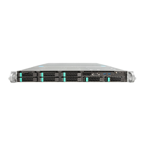
Figure 2. Intel® Server Chassis R1208WTXXX – 8 x 2.5” Front Drive Bay 1.2 Prepare Chassis for Assembly As received, the Intel Server Chassis will include several components within a boxed accessory kit or placed within the chassis. Remove the System Cover Note: A non-skid surface or a stop behind the server system may be needed to prevent the server system from sliding on your work surface. -
Page 18: Figure 4. Chassis Components
Intel ® Server System R1000WT Product Family System Integration and Service Guide Figure 4. Chassis Components The accessory kit will include the following components: • The left and right black plastic air duct side walls • The Chassis Support Bracket •... -
Page 19: Figure 5. System Fan Assembly Removal
Intel ® Server System R1000WT Product Family System Integration and Service Guide Figure 5. System Fan Assembly Removal System options to be installed in this chapter include: • The server board • The power supply module Installation instructions for all other system options and accessories can be found in the following chapters. -
Page 20: System Assembly
Intel ® Server System R1000WT Product Family System Integration and Service Guide 1.3 System Assembly Server Board Installation Figure 6. Server Board Installation Note: Follow ESD precautions outlined at the beginning of this manual • Carefully move aside any cables that may be taped to the chassis base to clear the area for server board placement. -
Page 21: Figure 7. Sas/Sata I/O Cable
Intel ® Server System R1000WT Product Family System Integration and Service Guide • Locate the SAS/SATA Data cable. • NOTE: If installing 2 cables (R1208WTxxxx), select the longer of the two. The 2 SAS/SATA cable is NOT installed at this time. -
Page 22: Figure 9. On-Board Mini-Sas Hd Connectors For Embedded Sata Support
Intel ® Server System R1000WT Product Family System Integration and Service Guide sSATA Ports 0 - 3 SATA Ports 0 - 3 Figure 9. On-Board Mini-SAS HD Connectors for embedded SATA Support • Locate the backplane power cable. Figure 10. Hot Swap Backplane Power Cable •... -
Page 23: Figure 12. System Fan Assembly Installation
Intel ® Server System R1000WT Product Family System Integration and Service Guide Install System Fan Assemblies Figure 12. System Fan Assembly Installation Figure 13. Connect System Fan Cables • Align fan assembly with mounting pins on the chassis base and push down until firmly seated (see letter “A”). -
Page 24: Figure 14. Hot Swap Backplane I
Intel ® Server System R1000WT Product Family System Integration and Service Guide • Locate the backplane I C cable. Figure 14. Hot Swap Backplane I C Cable • Attach the 1x5 pin connector (labeled “HSBP”) of the I C cable to the matching 1x5 pin connector (silk screened “HSBP I... -
Page 25: Figure 17. Front Control Panel And Front I/O Internal Cable Connections
Intel ® Server System R1000WT Product Family System Integration and Service Guide As received, the chassis should have three cables pre-attached on one end of each cable to the system front panel. The other end of the cables must be attached to matching connectors on the server board. The cables should be routed to the server board in the following order: (1) Front Control Panel, (2) Front Panel Video, and (3) Front Panel USB Ports. -
Page 26: Figure 18. Air Duct Side Wall And Support Bracket Installation
Attach the Blue 20-pin cable connector of the Front USB Cable (from the previous section) to the matching Blue 20- pin connector on the server board labeled “FP USB 2.0/3.0”. Push the cable down as far as possible into the cable routing channel. Install 2nd SAS/SATA Data Cable (For Intel® Server Chassis R1208WTxxx Only) Rev 2.2... - Page 27 Intel ® Server System R1000WT Product Family System Integration and Service Guide • Locate the SAS/SATA Data cable. • Attach the P1 (Straight Connector) end of each SAS/SATA Data cable to the specified mini-SAS HD connector on the backplane as shown below.
-
Page 28: Figure 19. Power Supply And Power Supply Bay Filler Installation
Intel ® Server System R1000WT Product Family System Integration and Service Guide Figure 19. Power Supply and Power Supply Bay Filler Installation • Insert the power supply module into the power supply bay until it clicks and locks into place (see letter “A”). -
Page 29: Essential System Component Installation And Service
Intel ® Server System R1000WT Product Family System Integration and Service Guide 2. Essential System Component Installation and Service Purpose This chapter provides instructions for the installation and removal of essential system components including processors, memory, storage devices, riser cards, and add-in cards. -
Page 30: Internal Cable Routing
Intel ® Server System R1000WT Product Family System Integration and Service Guide 2.1 Internal Cable Routing All cables should be routed using the cable channels along each chassis sidewall as shown in the following illustration. When routing cables front-to-back, none should be routed through the center of the system or in the area between the system fans and the DIMMs slots. -
Page 31: System Cover Removal / Installation
Intel ® Server System R1000WT Product Family System Integration and Service Guide 2.2 System Cover Removal / Installation 2.2.1 System Cover Removal The server system must be operated with the system cover in place to ensure proper cooling. The top cover must be removed to add or replace components inside of the system. -
Page 32: Air Duct Removal / Installation
Note: Product safety regulations in some countries require that the system include a 240VA safety screw to secure the top cover to the chassis. Use of this screw should be followed as appropriate in the country of use. Intel recommends installing this screw before the system is shipped to the end user site. -
Page 33: Processor Heatsink(S) Removal
Intel ® Server System R1000WT Product Family System Integration and Service Guide The CPU-1 processor + CPU heat sink must be installed first. The CPU-2 heat sink must be installed at all times, with or without a processor installed. When no processor is installed in a socket, one of the provided black mylar spacers should be attached to the top side of the plastic processor socket cover. -
Page 34: Processor Installation
Intel ® Server System R1000WT Product Family System Integration and Service Guide 2.4.2 Processor Installation Caution: Processor must be appropriate: You may damage the server board if you install a processor that is inappropriate for your server. For a web link to the list of compatible processor(s), see “Additional Information and Software”. -
Page 35: Figure 28. Processor Installation - Install The Processor
Intel ® Server System R1000WT Product Family System Integration and Service Guide CAUTION: The pins inside the processor socket are extremely sensitive. Other than the processor, no object should make contact with the pins inside the processor socket. A damaged processor socket pin will render the socket inoperable, and will produce erroneous processor or other system errors if used. -
Page 36: Figure 30. Processor Installation - Close The Load Plate
Intel ® Server System R1000WT Product Family System Integration and Service Guide Figure 30. Processor Installation – Close the Load Plate Carefully lower the load plate down over the processor. • Lock down the Load Plate. Figure 31. Processor Installation – Latch the Locking Lever Push down on the locking lever on the CLOSE 1st side (see letter ‘A’). -
Page 37: Processor Heatsink Installation
Intel ® Server System R1000WT Product Family System Integration and Service Guide 2.4.3 Processor Heatsink Installation Figure 32. Processor Heatsink Installation • If present, remove the protective film covering the Thermal Interface Material (TIM) on the bottom side of the heatsink (see letter “A”). -
Page 38: Memory Installation And Removal
Intel ® Server System R1000WT Product Family System Integration and Service Guide 2.5 Memory Installation and Removal 2.5.1 Memory Slot population requirements NOTE: Some system configurations may come with pre-installed DIMM blanks. DIMM blanks should only be removed when installing a DIMM in the same DIMM slot. Memory population rules apply when installing DIMMs. -
Page 39: Removing Memory
Intel ® Server System R1000WT Product Family System Integration and Service Guide 2.5.3 Removing Memory Figure 35. DDR4 DIMM Removal • Locate the DIMM sockets. Unlatch the retaining clips located on each end of the socket. The DIMM lifts from the socket. -
Page 40: Storage Device Installation / Removal
Intel ® Server System R1000WT Product Family System Integration and Service Guide 2.6 Storage Device Installation / Removal The 1U server system has support for several different storage device options. This section provides instruction for the installation and removal of front drive bay storage devices. -
Page 41: Figure 38. 3.5" Drive Installation - Mounting Drive To Carrier
Intel ® Server System R1000WT Product Family System Integration and Service Guide Figure 38. 3.5” Drive Installation – Mounting drive to carrier • Install the drive into the carrier. Verify the connector end of the drive is located towards the back of the carrier (see letter “D”). -
Page 42: X 2.5" Front Drive Bay Storage
Intel ® Server System R1000WT Product Family System Integration and Service Guide 2.6.1.4 3.5” Drive Carrier Insertion Figure 40. Drive Installation – Inserting 3.5” HDD assembly • With the lever open, insert the drive assembly into the drive bay (see letter “E”). -
Page 43: Riser Card Assembly - Removal / Integration / Installation
Intel ® Server System R1000WT Product Family System Integration and Service Guide • Remove the four screws securing the plastic drive blank to the carrier (see letter “C”) • Remove the drive blank from the carrier (see letter “D”) Figure 43. 2.5” Storage Device Installation – Mount Drive to Carrier •... -
Page 44: Riser Card Assembly Removal
Intel ® Server System R1000WT Product Family System Integration and Service Guide 2.7.1 Riser Card Assembly Removal Figure 45. PCI Riser Assembly Removal • Disconnect any cables attached to any add-in cards. Grasp the riser assembly with both hands and pull up to remove from the system. -
Page 45: Pci Add-In Card Installation
Intel ® Server System R1000WT Product Family System Integration and Service Guide 2.7.3 PCI Add-in Card Installation Figure 47. PCI Add-In Card Installation • Remove the PCI riser assembly from the system. (see section 2.7.1) • Remove the filler panel from the add-in card slot and remove the fastener screw as shown (see letter “A”). -
Page 46: Rack Handles - Installation / Removal
Note: The system should never be carried solely by the rack handles. Intel recommends carrying the system using two people or to use a cart when moving the system from one location to another. -
Page 47: Option And Accessory Kit Integration And Service
Intel ® Server System R1000WT Product Family System Integration and Service Guide 3. Option and Accessory Kit Integration and Service Purpose This chapter provides instructions for the integration of system components within a server system that has the server board and other system components pre-installed. It includes installation instructions for supported system options, and other available accessory option kits. -
Page 48: Slimline Optical Drive - Installation And Removal
Intel ® Server System R1000WT Product Family System Integration and Service Guide 3.1 Slimline Optical Drive – Installation and Removal This section provides installation and removal instructions for an optionally installed slimline SATA optical drive for systems that support the option. -
Page 49: Figure 54. Sata 4/5 Port On The Server Board
Intel ® Server System R1000WT Product Family System Integration and Service Guide Figure 54. SATA 4/5 Port on the Server Board • Locate the SATA cable and install it to either the “SATA 4” or “SATA 5” ports on the server board. -
Page 50: Slimline Optical Drive Removal
Intel ® Server System R1000WT Product Family System Integration and Service Guide 3.1.2 Slimline Optical Drive Removal NOTE: The slimline optical drive is NOT hot-swappable. Before removing or replacing the drive, you must first take the server out of service, turn off all peripheral devices connected to the system, turn off the system by pressing the power button, and unplugging the power cord from the system or wall outlet. -
Page 51: Power Supply Module - Installation / Removal
Intel ® Server System R1000WT Product Family System Integration and Service Guide 3.2 Power Supply Module – Installation / Removal 3.2.1 Power Supply Module Installation Figure 57. Power Supply Module Installation • (If installed) Remove the insert from the chassis power supply bay •... -
Page 52: Power Cord Retention Strap Installation
Intel ® Server System R1000WT Product Family System Integration and Service Guide 3.3 Power Cord Retention Strap Installation Retention Strap Receiver Hole Figure 59. Power Cord Retention Strap Installation • Locate the power cord retention strap from the system accessory kit. -
Page 53: Intel® Sas Raid Module Installation / Removal
Intel ® Server System R1000WT Product Family System Integration and Service Guide 3.4 Intel® SAS RAID Module Installation / Removal 3.4.1 Intel® SAS RAID Module Installation Figure 60. Intel® SAS RAID Module Installation • Insert the four barrel standoffs into the matching holes in the server board. -
Page 54: I/O Expansion Module - Installation / Removal
Server System R1000WT Product Family System Integration and Service Guide ® 3.5 Intel I/O Expansion Module – Installation / Removal 3.5.1 Intel® I/O Expansion Module Installation ® I/O Expansion Module Figure 61. Installing Intel • To remove the filler panel, squeeze the side panels and push it out of the chassis (see letter “A”) •... -
Page 55: Sata Raid 5 Upgrade Key - Installation / Removal
Intel ® Server System R1000WT Product Family System Integration and Service Guide • Remove the system cover. See section 2.2.1. • Remove the three screws as shown (see letter “A”). • Carefully pull up on the I/O Module until it disengages from the server board (see letter “B”). -
Page 56: Intel Remote Management Module 4 Lite Key - Installation / Removal
• Remove the Intel® RMM4 Lite key from its packaging • Locate the Intel® RMM4 Lite connector on the server board near the back of the server board next to the I/O Module connector • Place the Intel® RMM4 Lite key over the connector and match the orientation of the key to that of the connector •... -
Page 57: Trusted Platform Module (Tpm) Installation
Intel ® Server System R1000WT Product Family System Integration and Service Guide 3.8 Trusted Platform Module (TPM) Installation Figure 65. Trusted Platform Module (TPM) Installation • Locate the TPM module connector on the server board near the Riser Slot 1. -
Page 58: Front Bezel - Installation / Removal
Server System R1000WT Product Family System Integration and Service Guide 3.9 Front Bezel – Installation / Removal The system supports the installation of an optional front bezel (Intel product code A1UBEZEL). The Bezel kit includes a plastic lockable front bezel and multiple bezel Snap-ons allowing for OEM differentiation. -
Page 59: Front Bezel Installation
Intel ® Server System R1000WT Product Family System Integration and Service Guide 3.9.2 Front Bezel Installation Figure 68. Installing the Front Bezel Note: Before installing the bezel, you must install the rack handles (see section 2.9.1) • Lock the right side of the bezel to the rack handle (see letter “A”). -
Page 60: Intel Raid Maintenance Free Backup Unit (Rmfbu) Installation/Removal
3.10.1 Intel RAID Maintenance Free Backup Unit (RMFBU) Installation Figure 70. Intel® RAID Maintenance Free Backup Unit (RMFBU) Installation • The RMFBU mounting plate is located in between the two system fan assemblies. Align the tabs on the bottom side of the RMFBU assembly with the mounting holes in the mounting plate (see letter “A”) -
Page 61: Intel Raid Maintenance Free Backup Unit (Rmfbu) Removal
• Disconnect the cable between the RMFBU and the RAID card • Slide the Intel® RAID Maintenance Free Backup Unit to the right to disengage it from the mounting plate (see letter “A”) • Lift the RMFBU up to remove it from the server chassis (see letter “B”) -
Page 62: Dual Intel
RAID Maintenance Free Backup Units (RMFBU) Installation/Removal The 1U chassis has support for an optional dual RMFBU mounting assembly. (Intel Accessory Kit product code AWTAUXBBUBKT). The kit includes RMFBU mounting options for both a 1U and 2U server system. For the 1U chassis, only the plastic dual RMFBU housing and small mounting plate are used from the kit. -
Page 63: Figure 74. Rmfbu Removal From Standard Housing
Intel ® Server System R1000WT Product Family System Integration and Service Guide Figure 74. RMFBU Removal from standard housing • Remove the two RMFBUs from their original plastic housing • Locate the dual RMFBU plastic housing from the accessory kit Figure 75. -
Page 64: Dual Intel
Intel ® Server System R1000WT Product Family System Integration and Service Guide ® 3.11.2 Dual Intel RAID Maintenance Free Backup Unit (RMFBU) Assembly Removal To disengage the dual RMFBU assembly from the mounting plate: Figure 77. Dual RMFBU Assembly Removal •... -
Page 65: System Software Updates And Configuration
The FRUSDR utility for the given server platform can be downloaded as part of the uEFI only System Update Package (SUP) or multiple operating system supported One-boot Firmware Update (OFU) package, both of which can be downloaded from the Intel web site referenced above. The Update Packages will include full system update instructions. -
Page 66: No Access To The Bios Setup Utility
Intel ® Server System R1000WT Product Family System Integration and Service Guide 4.2.2 No Access to the BIOS Setup Utility If the BIOS Setup Utility is not accessible by hitting the <F2> key or other described access methods, it may be necessary to restore the BIOS default settings. - Page 67 Intel ® Server System R1000WT Product Family System Integration and Service Guide Option Description The <Tab> key is used to move between fields. For example, <Tab> Select Field <Tab> can be used to move from hours to minutes in the time ...
-
Page 68: System Packaging Assembly
5. System Packaging Assembly The original Intel packaging, in which the server system is delivered, is designed to provide protection to a fully configured system and was tested to meet ISTA (International Safe Transit Association) Test Procedure 3A (2008). The packaging was also designed to be re-used for shipment after system integration has been completed. -
Page 69: System Packaging Assembly Instructions
Intel ® Server System R1000WT Product Family System Integration and Service Guide 5.2 System Packaging Assembly Instructions System LEFT Side System System FRONT BACK System RIGHT Side Figure 78. Package Assembly Reference Diagram • Place 4 foam inserts into the inner box as shown. Note foam insert orientation •... - Page 70 Intel ® Server System R1000WT Product Family System Integration and Service Guide • Place 4 corrugated double wall cardboard pads onto the 2 bottom foam inserts as shown • Carefully place the system into the shipping bag. Tape the bag shut.
- Page 71 Intel ® Server System R1000WT Product Family System Integration and Service Guide • At the front of the system, between the end foam insert and system front panel, place the corrugated cardboard insert (iPN - H50583-002) • At the back of the system, place the corrugated cardboard insert (iPN H55264-001) between the foam insert and the system back panel as shown •...
- Page 72 Intel ® Server System R1000WT Product Family System Integration and Service Guide • Place 2 remaining foam inserts on top of the cardboard panels in the positions shown. • Fold the top flaps of the inner box closed. End flaps first, followed by side flaps.
- Page 73 Intel ® Server System R1000WT Product Family System Integration and Service Guide • Fold the top flaps of the outer box. End flaps first, followed by the side flaps. • Tape the outer box using an H-pattern. Across the center first, followed by both ends...
-
Page 74: System Service - System Features Overview
The intent of this chapter is to provide service personnel a reference to identify and locate the features associated with the Intel® Server System R1000WT product family. Additional information for this product family can be obtained from the following Intel documents which can be downloade from the following Intel web site: http://www.intel.com/support... -
Page 75: Control Panel Features
Intel ® Server System R1000WT Product Family System Integration and Service Guide 6.1.2 Control Panel Features Figure 82. Control Panel Features 6.1.3 Front I/O Features Video USB 2.1 / 3.0 Video SATA Slim-line Optical Drive USB 2.1 / 3.0 Figure 83. Front I/O Panel Features 6.1.4... -
Page 76: Server Board Features
Intel ® Server System R1000WT Product Family System Integration and Service Guide 6.1.5 Server Board Features Figure 85. Server Board Feature Identification Rev 2.2... -
Page 77: Figure 86. Intel Light-Guided Diagnostic Leds - Server Board
Intel ® Server System R1000WT Product Family System Integration and Service Guide Figure 86. Intel ® Light-Guided Diagnostic LEDs - Server Board Rev 2.2... -
Page 78: Figure 87. Dimm Fault Leds
Intel ® Server System R1000WT Product Family System Integration and Service Guide Figure 87. DIMM Fault LEDs Figure 88. System Fan Connections Rev 2.2... -
Page 79: System Configuration And Recovery Jumpers
Intel ® Server System R1000WT Product Family System Integration and Service Guide 6.2 System Configuration and Recovery Jumpers Figure 89. System Configuration and Recovery Jumpers The following sections describe how each jumper block is used. 6.2.1 BIOS Default Jumper Block This jumper resets BIOS options, configured using the <F2>... -
Page 80: Password Clear Jumper Block
This jumper should only be used if the ME firmware has gotten corrupted and requires re-installation. The following procedure should be followed. Note: System Update files are included in the System Update Packages (SUP) posted to Intel’s Download center web site. -
Page 81: Bmc Force Update Jumper Block
This jumper should only be used if the BMC firmware has gotten corrupted and requires re-installation. The following procedure should be followed: Note: System Update files are included in the System Update Packages (SUP) posted to Intel’s Download center web site. - Page 82 Intel ® Server System R1000WT Product Family System Integration and Service Guide Note: System Update Packages (SUP) can be downloaded from Intel’s download center web site. http://downloadcenter.intel.com 1. Turn off the system. 2. For safety, remove the AC power cords 3.
-
Page 83: System Service - Fru Replacement
Intel ® Server System R1000WT Product Family System Integration and Service Guide 7. System Service - FRU Replacement Purpose This chapter provides instruction for the removal and installation of system components considered as field replaceable. Instruction for the removal and installation of add-in options is documented in Chapters 2 and 3. These include: •... -
Page 84: System Fan Assembly Removal / Installation
Intel ® Server System R1000WT Product Family System Integration and Service Guide 7.1 System Fan Assembly Removal / Installation For integration or replacement of some system components, it may be easier or necessary to remove one or both of the system fan assemblies. -
Page 85: Replacing A System Fan
Connect the fan cables in order to the 10-pin fan connectors on the server board 7.2 Replacing a System Fan System fans used in the Intel Server System R1000WT product family are NOT hot-swappable. Figure 93. Remove a failed system fan •... -
Page 86: Replacing The System Battery
Intel ® Server System R1000WT Product Family System Integration and Service Guide 7.3 Replacing the System Battery The battery on the server board powers the Real Time Clock for up to 10 years in the absence of power. When the battery starts to weaken, it loses voltage, and stored server settings and system clock and date settings maybe lost. -
Page 87: Replacing A Backplane
Installing the Backplane Figure 96. Installing the Backplane • Locate the replacement 1U backplane (Intel product Code – FR1304S3HSBP or F1U8X25S3HSBP). • Hold the backplane only by the edges. Do not push or pull on any components on the backplane. Position the backplane to the server system guides at the front of the server system (see letter “A”). -
Page 88: Replacing The Standard Front Control Panel
7.5.2 Standard Front Control Panel Installation • Locate and remove the replacement control panel board from its packaging - Intel Product Code - FXXFPANEL Figure 98. Standard Front Control Panel Installation • Install the control panel board into the chassis (see letter “A”) Note: Ensure the plastic gasket over the control panel buttons is securely in place before installing the control panel board into the drive bay module. - Page 89 Intel ® Server System R1000WT Product Family System Integration and Service Guide • The control panel is properly positioned when the buttons are protruding from the Control Panel face plate on the front of the drive bay module and the screw holes on the top of the assembly are aligned.
-
Page 90: Replacing The Server Board
• Remove all options installed onto the server board including (if installed): Intel® I/O Module, Intel® SAS RAID Module and mounting stand-offs, Intel® RAID 5 option key, Intel® RMM 4 Lite key, TPM Module, eUSB SSD and mounting stand-off •... -
Page 91: Figure 99. Server Board Removal
Intel ® Server System R1000WT Product Family System Integration and Service Guide Figure 99. Server Board Removal • Remove the 8 fastener screws used to secure the server board to the chassis (see letter “C”) • Carefully lift server board from the chassis (see letter “D”) and place into anti-static bag... -
Page 92: Server Board Installation
Intel ® Server System R1000WT Product Family System Integration and Service Guide 7.6.2 Server Board Installation Note: Follow ESD precautions outlined at the beginning of this manual • See Section 1.3 Server Building Block System Integration • Install processor(s) (see section 2.4.2) •... - Page 93 Intel ® Server System R1000WT Product Family System Integration and Service Guide <Blank Page> Rev 2.2...
-
Page 94: Appendix A: Getting Help
— Server and chassis accessory parts list for ordering upgrades or spare parts — A searchable knowledgebase to search for product information throughout the support site If you are still unable to obtain a solution to your issue, send an email to Intel’s technical support center using the online form available at http://www.intel.com/p/en_US/support/contactsupport... -
Page 95: Appendix B: System Cable Routing Diagrams
Intel ® Server System R1000WT Product Family System Integration and Service Guide Appendix B: System Cable Routing Diagrams Rev 2.2... - Page 96 Intel ® Server System R1000WT Product Family System Integration and Service Guide Rev 2.2...
-
Page 97: Appendix C: System Status Led Operating States And Definition
Intel ® Server System R1000WT Product Family System Integration and Service Guide Appendix C: System Status LED Operating States and Definition The server board includes a bi-color System Status LED. The System Status LED on the server board is tied directly to the System Status LED on the front panel. - Page 98 Intel ® Server System R1000WT Product Family System Integration and Service Guide Color State Criticality Description • BMC Watchdog has reset the BMC. • Power Unit sensor offset for configuration error is asserted. • HDD HSC is off-line or degraded.
-
Page 99: Appendix D: Post Code Diagnostic Led Decoder Table
Intel ® Server System R1000WT Product Family System Integration and Service Guide Appendix D: POST Code Diagnostic LED Decoder Table As an aid to assist in trouble shooting a system hang that occurs during a system”s Power-On Self Test (POST) process, the server board includes a bank of eight POST Code Diagnostic LEDs on the back edge of the server board. -
Page 100: Table 6. Mrc Progress Codes
Intel ® Server System R1000WT Product Family System Integration and Service Guide The MRC Progress Codes are displays to the Diagnostic LEDs that show the execution point in the MRC operational path at each step. Table 6. MRC Progress Codes... -
Page 101: Table 7. Mrc Fatal Error Codes
02h = Memory DIMMs on all channels of all sockets are disabled due to hardware memtest error. 3h = No memory installed. All channels are disabled. Memory is locked by Intel Trusted Execution Technology and is inaccessible DDR3 channel training error... -
Page 102: Table 8. Post Progress Codes
Intel ® Server System R1000WT Product Family System Integration and Service Guide BIOS POST Progress Codes The following table provides a list of all POST progress codes. Table 8. POST Progress Codes Diagnostic LED Decoder 1 = LED On, 0 = LED Off... - Page 103 Intel ® Server System R1000WT Product Family System Integration and Service Guide Diagnostic LED Decoder 1 = LED On, 0 = LED Off Checkpoint Upper Nibble Lower Nibble LED # Description DXE ACPI Init DXE CSM Init DXE BDS Started...
- Page 104 Intel ® Server System R1000WT Product Family System Integration and Service Guide Diagnostic LED Decoder 1 = LED On, 0 = LED Off Checkpoint Upper Nibble Lower Nibble LED # Description S3 Resume PEIM (S3 boot script) S3 Resume PEIM (S3 Video Repost)
-
Page 105: Appendix E: Post Code Errors
Note: The POST error codes in the following table are common to all current generation Intel server platforms. Features present on a given server board/system will determine which of the listed error codes are supported. - Page 106 Intel ® Server System R1000WT Product Family System Integration and Service Guide Error Code Error Message Response 8131 Processor 02 disabled Major 8160 Processor 01 unable to apply microcode update Major 8161 Processor 02 unable to apply microcode update Major...
- Page 107 Intel ® Server System R1000WT Product Family System Integration and Service Guide Error Code Error Message Response 853A DIMM_J3 failed test/initialization Major 853B DIMM_K1 failed test/initialization Major 853C DIMM_K2 failed test/initialization Major 853D DIMM_K3 failed test/initialization Major 853E DIMM_L1 failed test/initialization...
- Page 108 Intel ® Server System R1000WT Product Family System Integration and Service Guide Error Code Error Message Response 8564 DIMM_B2 encountered a Serial Presence Detection (SPD) failure Major 8565 DIMM_B3 encountered a Serial Presence Detection (SPD) failure Major 8566 DIMM_C1 encountered a Serial Presence Detection (SPD) failure...
- Page 109 Intel ® Server System R1000WT Product Family System Integration and Service Guide Error Code Error Message Response 85D1 DIMM_M1 disabled Major 85D2 DIMM_M2 disabled Major 85D3 DIMM_M3 disabled Major 85D4 DIMM_N1 disabled Major 85D5 DIMM_N2 disabled Major 85D6 DIMM_N3 disabled...
-
Page 110: Table 10. Post Error Beep Codes
Codes that are common across all Intel server boards and systems that use same generation chipset are listed in the following table. Each digit in the code is represented by a sequence of beeps whose count is equal to the digit. -
Page 111: Table 11. Integrated Bmc Beep Codes
Intel ® Server System R1000WT Product Family System Integration and Service Guide Table 11. Integrated BMC Beep Codes Code Associated Sensors Reason for Beep 1-5-2-1 No CPUs installed or first CPU socket is CPU1 socket is empty, or sockets are populated empty. - Page 112 Intel ® Server System R1000WT Product Family System Integration and Service Guide NOTES ______________________________________________________________________________________________________ ______________________________________________________________________________________________________ ______________________________________________________________________________________________________ ______________________________________________________________________________________________________ ______________________________________________________________________________________________________ ______________________________________________________________________________________________________ ______________________________________________________________________________________________________ ______________________________________________________________________________________________________ ______________________________________________________________________________________________________ ______________________________________________________________________________________________________ ________________________________________________________________________________________________ ______________________________________________________________________________________________________ ______________________________________________________________________________________________________ ______________________________________________________________________________________________________ ______________________________________________________________________________________________________ ______________________________________________________________________________________________________ ______________________________________________________________________________________________________ ______________________________________________________________________________________________________ ______________________________________________________________________________________________________ ______________________________________________________________________________________________________ ______________________________________________________________________________________________________ ________________________________________________________________________________________________ ______________________________________________________________________________________________________ ______________________________________________________________________________________________________ ______________________________________________________________________________________________________ ______________________________________________________________________________________________________ ______________________________________________________________________________________________________...
Need help?
Do you have a question about the R1000WT Series and is the answer not in the manual?
Questions and answers