IBM TotalStorage DS300 Hardware Installation And User's Manual
Hide thumbs
Also See for TotalStorage DS300:
- Best practices manual (680 pages) ,
- Hardware installation and user's manual (110 pages) ,
- Quick installation manual (13 pages)
Table of Contents
Advertisement
Quick Links
Advertisement
Table of Contents

Subscribe to Our Youtube Channel
Related Manuals for IBM TotalStorage DS300


Summary of Contents for IBM TotalStorage DS300
- Page 1 TotalStorage DS300 and DS400 Hardware Installation and User’s Guide...
- Page 3 TotalStorage DS300 and DS400 Hardware Installation and User’s Guide...
- Page 4 Note: Before using this information and the product it supports, read the general information in Appendix C, “Notices,” on page 87. Fifth Edition (October 2005) © Copyright International Business Machines Corporation 2004, 2005. All rights reserved. US Government Users Restricted Rights – Use, duplication or disclosure restricted by GSA ADP Schedule Contract with IBM Corp.
- Page 5 Vor der Installation dieses Produkts die Sicherheitshinweise lesen. Prima di installare questo prodotto, leggere le Informazioni sulla Sicurezza. Les sikkerhetsinformasjonen (Safety Information) før du installerer dette produktet. Antes de instalar este produto, leia as Informações sobre Segurança. © Copyright IBM Corp. 2004, 2005...
- Page 6 Antes de instalar este producto, lea la información de seguridad. Läs säkerhetsinformationen innan du installerar den här produkten. Hardware Installation and User’s Guide...
- Page 7 All caution and danger statements in this documentation begin with a number. This number is used to cross reference an English caution or danger statement with translated versions of the caution or danger statement in the IBM Safety Information book.
- Page 8 Statement 2: CAUTION: When replacing the lithium battery, use only IBM Part Number 33F8354 or an equivalent type battery recommended by the manufacturer. If your system has a module containing a lithium battery, replace it only with the same module type made by the same manufacturer.
- Page 9 Statement 3: CAUTION: When laser products (such as CD-ROMs, DVD drives, fiber optic devices, or transmitters) are installed, note the following: v Do not remove the covers. Removing the covers of the laser product could result in exposure to hazardous laser radiation. There are no serviceable parts inside the device.
- Page 10 Statement 4: ≥ 18 kg (39.7 lb) ≥ 32 kg (70.5 lb) ≥ 55 kg (121.2 lb) CAUTION: Use safe practices when lifting. Statement 5: CAUTION: The power control button on the device and the power switch on the power supply do not turn off the electrical current supplied to the device.
- Page 11 Statement 8: CAUTION: Never remove the cover on a power supply or any part that has the following label attached. Hazardous voltage, current, and energy levels are present inside any component that has this label attached. There are no serviceable parts inside these components.
- Page 12 Hardware Installation and User’s Guide...
-
Page 13: Table Of Contents
Chapter 1. Introduction ..... . 1 The IBM Documentation CD ....1 Hardware and software requirements . - Page 14 Connecting secondary interface cables for storage management ..42 Connecting an IBM EXP400 expansion unit to a DS400 storage subsystem Chapter 8. DS400 storage subsystem controls and LEDs ..45 DS400 storage subsystem front view .
- Page 15 Chapter 11. Configuring the storage subsystem for out-of-band management ......81 Appendix A. Storage subsystem ID and records ... 83 Appendix B.
- Page 16 Hardware Installation and User’s Guide...
-
Page 17: Chapter 1. Introduction
These updates are available from the IBM Web site. To check for updated documentation and technical updates, complete the following steps: 1. -
Page 18: Using The Documentation Browser
User’s Guide, the following documentation comes with the storage subsystem or is available on the IBM Support Web site: v IBM TotalStorage DS300 and DS400 Quick Installation Guide This printed document contains the basic information you need to get the storage subsystem installed and running. -
Page 19: Notices And Statements Used In This Document
It uses flowcharting techniques to guide you in the isolation and correction of problems. v IBM TotalStorage DS300 and DS400 Hardware Maintenance Manual This document is in PDF on the IBM Support Web site. It contains information to help you solve problems yourself, and it contains information for service technicians. -
Page 20: Specifications
Specifications The following information is a summary of the specifications of the storage subsystem. Depending on the storage subsystem model, some specifications might not apply. Table 1. DS300 and DS400 storage subsystems operating specifications Size (measured from front of hard disk Environment Acoustical noise emissions: drive to rear of unit) -
Page 21: Chapter 2. Planning The Ds300 Storage Subsystem Configuration
The following illustration shows the direct-management method. DS300 single-controller storage subsystem iSCSI controller Site Ethernet network DS300 dual-controller storage subsystem Host server iSCSI controller iSCSI controller Ethernet connection Management station Figure 1. Direct management of iSCSI storage subsystems © Copyright IBM Corp. 2004, 2005... -
Page 22: Ds300 Storage Subsystem Configuration Examples
DS300 storage subsystem configuration examples This section shows basic and complex example configurations that you can use for your DS300 iSCSI storage subsystem and storage network. Important: v Do not configure any two interfaces on the same system to be on the same subnet. -
Page 23: Multiple Port, Single Server Configuration
Multiple port, single server configuration A system with dual iSCSI ports provides enhanced performance compared to a system with a single iSCSI port. The following illustration is an example of a multiple port, single server configuration. Host system with two iSCSI connectors Gigabit Ethernet... -
Page 24: Single Port, Two-Server Configuration
Single port, two-server configuration The following illustration is an example of a single port, two server configuration. Host system Host system with one iSCSI with one iSCSI connector connector Gigabit Ethernet switch DS300 Figure 4. Single port, two-server configuration (DS300) Hardware Installation and User’s Guide... -
Page 25: Multiple Port, Multiple Server Configuration
Multiple port, multiple server configuration This configuration can also be used for cluster operation. You can replace the two Gb Ethernet switches shown in Figure 5 with one large Gb Ethernet switch that has the required number of ports. Virtual Local Area Network (VLAN) can also be used to isolate the two iSCSI networks, instead of a single switch. -
Page 26: Multiple Port, Multiple Server, Multiple Storage Subsystem Configuration
Multiple port, multiple server, multiple storage subsystem configuration You can replace the two Gb Ethernet switches shown in Figure 6 with one large Gb Ethernet switch that has the required number of ports. VLAN can also be used to isolate the two iSCSI networks, instead of a single switch. Host system Host system with two iSCSI... -
Page 27: Multiple Port, Multiple Server, Dual-Controller Storage Subsystem Configuration
Multiple port, multiple server, dual-controller storage subsystem configuration This configuration can also be used for cluster operation. You can replace the two Gb Ethernet switches shown in Figure 8 with one large Gb Ethernet switch that has the required number of ports. Virtual Local Area Network (VLAN) can also be used to isolate the two iSCSI networks, instead of a single switch. - Page 28 Hardware Installation and User’s Guide...
-
Page 29: Chapter 3. Installing And Cabling The Ds300 Storage Subsystem
After you unpack the storage subsystem, make sure that you have the items that are described in this section. Hardware The IBM TotalStorage DS300 storage subsystem (1701-1RL) comes with the following components: v One iSCSI RAID controller v One power supply... -
Page 30: Components Of The Ds300 Storage Subsystem
Rack Mounting Assembly kit, including: – Rack Installation Instructions – Rack mounting template (for aligning the rails correctly) If an item is missing or damaged, contact your IBM marketing representative or authorized reseller. The following documents are available on the IBM Support Web site:... -
Page 31: Ds300 Storage Subsystem Rear View
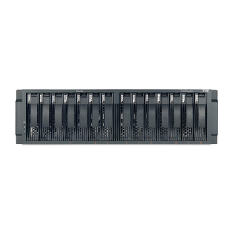
Drive filler panel Hard disk drive Figure 10. DS300 storage subsystem models 1701-1RS and 1701-2RD front components Hard disk drive You can install up to 14 Ultra320 hot-swap hard disk drive customer replaceable units (CRUs) in the storage subsystem. Each hard disk drive CRU contains a hard disk drive and tray. - Page 32 Power supply Power supply filler panel ISCSI RAID controller RAID controller with one Gb Ethernet filler panel connector (Side B) (Side A) Figure 11. DS300 storage subsystem model 1701-1RL rear view Power supplies iSCSI RAID controller RAID controller with three Gb Ethernet filler panel connectors (Side B)
-
Page 33: Cache Memory And Raid Controller Battery
3. Remove the storage subsystem from its shipping container and check the contents (for a list of items, see “Inventory checklist” on page 13). If any items are missing, contact your IBM marketing representative or authorized reseller before proceeding. 4. Assemble the tools and equipment that you will need for installation. These... -
Page 34: Connecting Secondary Interface Cables For Storage Management
Rack-mounting hardware (comes with the storage subsystem) v IBM ServeRAID Manager software to configure the storage subsystem (comes with the storage subsystem on the IBM ServeRAID Application CD 5. Install the storage subsystem in the rack. Rack mounting instructions and a template for aligning the holes in the rails and the rack come with the storage subsystem. -
Page 35: Chapter 4. Ds300 Storage Subsystem Controls And Leds
Note: If the fault LED is lit continuously (not flashing), there is a problem with the storage subsystem. Use the ServeRAID Manager program to diagnose and repair the problem. For more information, see the Problem Determination Guide. © Copyright IBM Corp. 2004, 2005... -
Page 36: Ds300 Storage Subsystem Rear View
Table 2. Front view LEDs (continued) Symbol Description Color Indication No label Hard disk drive Green When this LED is flashing, it indicates activity that the drive is in use. Each hard disk drive has an activity LED. No label Hard disk drive Amber When this LED is lit, it indicates that the... -
Page 37: Iscsi Raid Controller With One Ethernet Connector (Model 1701-1Rl) Controls And Leds
iSCSI RAID controller with one Ethernet connector (model 1701-1RL) controls and LEDs The following illustration shows an iSCSI RAID controller with one Ethernet connector (model 1701-1RL). Figure 17. iSCSI RAID controller LEDs, controls, and connectors (model 1701-1RL) Serial connectors (SP1 and SP2) The serial connectors are for diagnostic purposes only. -
Page 38: Iscsi Raid Controller With Three Ethernet Connectors (Models 1701-1Rs And 1701-2Rd) Controls And Leds
Table 3. iSCSI RAID controller LEDs (model 1701-1RL) (continued) LED symbol or label Description Color Indication Cache DIMM! RAID cache DIMM Amber When this LED is lit, it indicates that the cache fault memory has failed. This is based on one of the following conditions: v Cannot read the DIMM configuration data v Nonrecoverable ECC failure... - Page 39 The following table lists the LEDs on the iSCSI RAID controller (models 1701-1RS and 1701-2RD). Table 4. iSCSI RAID controller LEDs (models 1701-1RS and 1701-2RD) LED symbol or label Description Color Indication Controller ready Green When this LED is lit, it indicates that the controller has successfully started or restarted.
- Page 40 Table 4. iSCSI RAID controller LEDs (models 1701-1RS and 1701-2RD) (continued) LED symbol or label Description Color Indication ETH 2 Link GbE link status Green When this LED is lit, it indicates that the Gb Ethernet link is operational. ETH 2 TX/RX GbE activity Green When this LED is lit, it indicates that data...
-
Page 41: Chapter 5. Planning The Ds400 Storage Subsystem Configuration
DS400 single-controller storage subsystem Fibre Channel controller Fibre Channel connection DS400 dual-controller storage subsystem Host server Fibre Channel controller Fibre Channel controller Ethernet connection Management station Figure 19. Direct management of Fibre Channel storage subsystems (DS400) © Copyright IBM Corp. 2004, 2005... -
Page 42: Ds400 Storage System Configuration Examples
DS400 storage system configuration examples This section shows basic and complex example configurations that you can use for the Fibre Channel DS400 storage subsystem and storage network. Note: Switch zoning should be used to isolate data paths from the host server to the storage subsystem, especially in a heterogeneous operating-system environment. -
Page 43: Multiple Server, Single Storage Subsystem Configuration
Multiple server, single storage subsystem configuration The following illustration is an example of a multiple server, single storage subsystem configuration. Host system Host system with single host with single host adapter adapter Fibre Channel switch DS400 Figure 21. Multiple server, single storage subsystem configuration (DS400) Chapter 5. -
Page 44: Multiple Server, Multiple Switch, Single Storage Subsystem Configuration
Multiple server, multiple switch, single storage subsystem configuration The following illustration is an example of a multiple server, multiple switch, storage subsystem configuration. Host system Host system with single host with single host adapter adapter Fibre Fibre Channel Channel switch switch DS400 Figure 22. -
Page 45: Multiple Port, Multiple Server, Multiple Storage Subsystem Configuration
Multiple port, multiple server, multiple storage subsystem configuration The following illustration is an example of a multiple port, multiple server, multiple storage subsystem configuration. Host system Host system with two host with two host adapters adapters Fibre Channel Fibre switch Channel switch DS400... -
Page 46: Redundant Host And Drive Fibre Channel Configurations
Redundant host and drive Fibre Channel configurations Note: The following configurations have host and drive path failover protection and are preferred for high availability. Host system Host system Host system with two host with two host with two host adapters adapters adapters Fibre... -
Page 47: San Fabric Zone Configurations
SAN fabric zone configurations The following illustration is an example of a single SAN fabric zone configuration. Host system Host system with two host with two host adapters adapters Fibre Interswitch link Channel Fibre switch Channel switch DS400 Figure 25. Single SAN fabric zone configuration The following illustration is an example of a dual SAN fabric zone configuration. - Page 48 Hardware Installation and User’s Guide...
-
Page 49: Chapter 6. Installing The Ds400 Storage Subsystem
IBM Documentation CD, including: – IBM TotalStorage Types 1700 and 1701 Warranty and Support Information – IBM TotalStorage DS300 and DS400 Hardware Installation and User’s Guide – IBM TotalStorage DS300 and DS400 Software Installation Guide – Safety Information document v Rack Mounting Assembly kit, including: –... -
Page 50: Components Of Ds400 Storage Subsystems
– Rack mounting template (for aligning the rails properly) If an item is missing or damaged, contact your IBM marketing representative or authorized reseller. The following documents are available on the IBM Support Web site: v IBM TotalStorage DS300 Problem Determination Guide and IBM TotalStorage... -
Page 51: Ds400 Storage Subsystem Rear View
For information about installing and replacing a hard disk drive, see “Installing a hot-swap hard disk drive” on page 60 and “Replacing a hot-swap hard disk drive” on page 61. DS400 storage subsystem rear view The following illustrations show the components on the rear of the DS400 storage subsystems models 1700-1RS and 1700-2RD. -
Page 52: Cache Memory And Raid Controller Battery
Rack-mounting hardware (comes with the storage subsystem) v IBM ServeRAID Manager software to configure the storage subsystem (comes with the storage subsystem on the IBM ServeRAID 7.20 Application 5. Install the storage subsystem in the rack. Rack mounting instructions and a template for aligning the holes in the rails and the rack come with the storage subsystem. -
Page 53: Chapter 7. Cabling The Ds400 Storage Subsystem
RAID controller before you can connect the fiber-optic cable. v You must remove the fiber-optic cable from the SFP module before you remove the SFP module from the Fibre Channel connector. See “Removing an SFP module” on page 39 for more information. © Copyright IBM Corp. 2004, 2005... - Page 54 Installing an SFP module To install an SFP module, complete the following steps. Statement 3: CAUTION: When laser products (such as CD-ROMs, DVD drives, fiber optic devices, or transmitters) are installed, note the following: v Do not remove the covers. Removing the covers of the laser product could result in exposure to hazardous laser radiation.
- Page 55 4. Rotate the SFP module so that the plastic or wire tab is on the bottom; then, insert it into the host connector until it clicks into place. See Figure 31. Fibre Channel RAID controller SFP module Figure 31. Installing an SFP module into the host connector Removing an SFP module To remove an SFP module from a host connector, complete the following steps.
-
Page 56: Working With Fiber-Optic Cables
v For an SFP module that has a wire tab: a. Unlock the SFP module by pulling the wire tab downward 90° (see Figure 33). Wire Protective module Figure 33. Unlocking an SFP module - wire tab b. Pull the SFP module out of the connector. 4. - Page 57 Installing a fiber-optic cable To connect a fiber-optic cable, complete the following steps: 1. Read the information in “Handling a fiber-optic cable” on page 40. 2. Remove the protective caps from the fiber-optic cable end. See Figure 34. Fiber-optic cable Protective cap Figure 34.
-
Page 58: Connecting A Host To A Fibre Channel Raid Controller
Removing a fiber-optic cable To remove a fiber-optic cable, complete the following steps: 1. Read the information in “Handling a fiber-optic cable” on page 40. 2. Gently pull the fiber-optic cable from the SFP module that is installed in the host connector in a Fibre Channel RAID controller. -
Page 59: Connecting An Ibm Exp400 Expansion Unit To A Ds400 Storage Subsystem
2. Use the IBM 2M SCSI cable that comes with the expansion unit or use a 4.2M LVD SCSI cable to connect the EXP400 to the DS400 (see Figure 38 on page 44.) You can connect one or two expansion units. - Page 60 D 400 Channel 3 Channel 3 Fibre Channel RAID controllers EXP400 Channel 4 EXP400 Figure 38. Connecting two EXP400 expansion units to a DS400 dual-controller storage subsystem 3. Remove the hard disk drive filler panels on the EXP400 and install the hard disk drives.
-
Page 61: Chapter 8. Ds400 Storage Subsystem Controls And Leds
Note: If the fault LED is lit continuously (not flashing), there is a problem with the storage subsystem. Use the ServeRAID Manager program to diagnose and repair the problem. For more information, see the Problem Determination Guide. © Copyright IBM Corp. 2004, 2005... -
Page 62: Ds400 Storage Subsystem Rear View
Table 5. Front view LEDs (continued) Symbol Description Color Indication No label Hard disk drive Green When this LED is flashing, it indicates activity that the drive is in use. Each hard disk drive has an activity LED. No label Hard disk drive Amber When this LED is lit, it indicates that the... -
Page 63: Fibre Channel Raid Controller Controls And Leds
FC 0 connector The FC 0 connector is for Fibre Channel data transfer. SCSI channel 4 SCSI channel 4 can be connected to an IBM EXP400 Storage Expansion Unit. SCSI channel 3 SCSI channel 3 can be connected to an IBM EXP400 Storage Expansion Unit. - Page 64 Table 6. Fibre Channel RAID controller LEDs (continued) LED symbol or label Description Color Indication Battery fault Amber When this LED is lit, it indicates that the battery cannot sustain the RAID controller memory in case of power loss. This might be caused by any of the following conditions: v The battery is removed.
- Page 65 The Fibre Channel RAID controller has two status LEDs on each of the two Fibre Channel host connectors. The following tables show the Fibre Channel host connector status LEDs. Table 7. Fiber Channel host connector status for LED 9 and LED 10 Name LED 9 green LED 10 amber...
- Page 66 Hardware Installation and User’s Guide...
-
Page 67: Chapter 9. Turning The Storage Subsystem On And Off
Restart or turn on the power to the host. 3. Turn on the power to each device, according to the power-on sequence in step 2. To turn on power to the storage subsystem, turn on the power-supply © Copyright IBM Corp. 2004, 2005... -
Page 68: Turning Off The Storage Subsystem
switches on the back of the storage subsystem. You must turn on both power-supply switches to take advantage of the redundant power supplies. 4. Use the ServeRAID Manager program and the fault LEDs to check the overall status of the storage subsystem and its components. All LEDs should be green on the front of the storage subsystem. -
Page 69: Restoring Power After An Unexpected Shutdown
v All of the green drive-active LEDs on the front of the storage subsystem (and on all attached expansion units) are not flashing. v The green cache-active LEDs on the back of the storage subsystem are off. 4. From the ServeRAID Manager interface, shut down the RAID controller to flush the data from the cache. -
Page 70: Performing An Emergency Shutdown
If the storage subsystem shuts down unexpectedly but there is still power to the site, use the ServeRAID Manager program to determine whether the storage subsystem has overheated. v If an overtemperature condition is indicated, use the procedure in “Restoring power after an overtemperature shutdown”... -
Page 71: Monitoring Status Through Software
4. Complete step 2 on page 51 to determine the correct power-on sequence for the system. 5. When the internal temperature of the storage subsystem is below 45°C (113°F), complete steps 3 on page 51 and 4 on page 52 to turn on power to the devices in the system and to check the status of the storage subsystem. - Page 72 Hardware Installation and User’s Guide...
-
Page 73: Chapter 10. Installing And Replacing Components
To reduce the possibility of damage from electrostatic discharge, observe the following precautions: v Limit your movement. Movement can cause static electricity to build up around you. © Copyright IBM Corp. 2004, 2005... -
Page 74: Installing And Removing The Bezel On Ds300 (Models 1701-1Rs And 1701-2Rd) And Ds400 Storage Subsystems
v Wear an electrostatic-discharge wrist strap, if one is available. v Handle the device carefully, holding it by its edges or its frame. v Do not touch solder joints, pins, or exposed circuitry. v Do not leave the device where others can handle and damage it. v While the device is still in its static-protective package, touch it to an unpainted metal part of the storage subsystem for at least 2 seconds. -
Page 75: Installing And Removing The Bezel On The Ds300 Model 1701-1Rl Storage Subsystem
To remove the bezel, complete the following steps: 1. Press in on the blue tab on the top outside edge of both sides of the bezel, and pull the top of the bezel slightly away from the storage subsystem. 2. Pull the bezel up to release the three tabs at the bottom edge of the bezel. Store the bezel in a safe place. -
Page 76: Installing A Hot-Swap Hard Disk Drive
The storage subsystem supports up to 14 IBM Ultra320 SCSI hard disk drives. Each of these IBM drives comes preassembled in a drive tray, ready for installation. (Do not detach the drive from the tray.) Be sure to record the location information for each drive in Table 10 on page 83. -
Page 77: Replacing A Hot-Swap Hard Disk Drive
ServeRAID information: In some cases, the ServeRAID Manager program will automatically reset the drive to the Hot Spare or Rebuild state. If the drive-state change does not occur automatically (the amber LED stays lit), see the ServeRAID Manager program online help for information about changing the state of the drive from the current state to another state, such as Hot Spare or Ready. -
Page 78: Adding Larger-Capacity Drives
d. Make sure that there is proper identification (such as a label) on the hard disk drive; then, gently slide it completely out of the storage subsystem. 5. Install the new hard disk drive: a. Gently push the drive into the empty bay until the tray handle touches the storage subsystem tray. - Page 79 Attention: When you handle static-sensitive devices, take precautions to avoid damage from static electricity. For details about handling static-sensitive devices, see “Handling static-sensitive devices” on page 57. 4. Unpack the new drives. Set the drives on a dry, level surface away from magnetic fields. Save the packing material and documentation in case you have to return the drives.
-
Page 80: Replacing The Round Lithium Battery In The Raid Controller
Statement 2: CAUTION: When replacing the lithium battery, use only IBM Part Number 46H4132 or an equivalent type battery. If your system has a module containing a lithium battery, replace it only with the same module type. The battery contains lithium and can explode if not properly used, handled, or disposed of. - Page 81 4. For storage subsystems with two controllers installed: Move the I/O data to the alternate controller: a. Open a Telnet session and connect to the alternate controller management port IP address. b. At the command prompt, enter admin. c. Enter the administrator password. d.
-
Page 82: Replacing The Cache Battery In The Raid Controller
9. Insert the new battery: a. Tilt the battery so that you can insert it into the socket on the side opposite the battery clip. b. Press the battery down into the socket until it clicks into place. Make sure that the battery socket holds the battery securely. - Page 83 Each RAID controller contains a rechargeable battery that maintains the data in the cache memory for three days without power to the unit. If the ServeRAID Manager program instructs you to replace the battery because the current battery has failed or is nearing its expiration date, complete the following steps to replace the battery.
- Page 84 RAID controller RAID controller filler panel Figure 47. Removing a RAID controller b. Grasp both latches and pull the controller out of the bay. c. Place the controller on a dry, level surface. 10. Remove the cache battery from the controller: a.
- Page 85 Battery Connector Figure 49. Installing a cache battery in the RAID controller b. Press down on the blue lift tab to secure the battery to the connector. c. Tighten the thumbscrew. 13. Install the RAID controller: a. Make sure that the lever on each side of the controller is down as far as it will go.
-
Page 86: Replacing A Memory Module
19. Use the ServeRAID Manager program to monitor the status of the storage subsystem. Replacing a memory module Follow the procedure in this section to do the following tasks: v Replace the cache dual inline memory module (DIMM) if the amber LED is lit. v Install the 1 GB system DIMM upgrade option (purchased separately) v Replace a system DIMM that has failed. - Page 87 RAID controller RAID controller filler panel Figure 50. Removing a RAID controller b. Grasp both latches and pull the controller out of the bay. c. Place the controller on a dry, level surface. Attention: To avoid breaking the retaining clips or damaging the DIMM connectors, open and close the clips gently.
-
Page 88: Replacing A Raid Controller
Figure 52. Inserting a DIMM into the connector e. Insert the DIMM into the connector by aligning the edges of the DIMM with the slots at the ends of the DIMM connector. Firmly press the DIMM into the connector by applying pressure on both ends of the DIMM simultaneously. -
Page 89: Replacing The Hardware
inside the RAID controller that you are replacing and install them in the replacement RAID controller. The steps to remove and install the battery and DIMM are included in the following procedure. 2. The RAID controller in the DS300 model 1701-1RL does not contain a cache battery. - Page 90 Battery Connector a. Slide the battery under the tab near the front of the controller. b. Press down on the blue lift tab to secure the battery to the connector. c. Tighten the thumbscrew. 9. Remove the RAID cache DIMM from the failed controller. System DIMM Cache DIMM a.
-
Page 91: Configuring The Management Port
the procedure to replace the 512 MB system DIMM on the replacement controller with the 1 GB system DIMM from the failed controller. 11. Install the replacement controller: a. Make sure that the lever on each side of the controller is down as far as it will go. -
Page 92: Setting The Ip Addresses For Ds300 Iscsi Ports
5. Enter save to save the modified settings. See the IBM TotalStorage DS300 Problem Determination Guide or IBM TotalStorage DS400 Problem Determination Guide on the IBM Support Web site for a list of all the available commands. Importing foreign arrays... -
Page 93: Replacing A Hot-Swap Power Supply
Using the command-line interface to import arrays To use the command-line interface to import foreign arrays, complete the following steps: 1. Make sure that you have established a Telnet session to the management port of the replacement controller. 2. Enter array import foreign_array where foreign_array is the name of the foreign array. -
Page 94: Adding A Power Supply (Ds300 Model 1701-1Rl Only)
b. Push the power supply into the bay until it meets resistance (approximately 6 mm [0.25 in.] from the end of the chassis). c. While squeezing together the latch and lever, push both latches up as far as they will go. The power supply will slide the rest of the way into the bay. 7. - Page 95 10. Remove the 7-disk drive cover from the bezel and install the bezel (see “Installing and removing the bezel on DS300 (models 1701-1RS and 1701-2RD) and DS400 storage subsystems” on page 58). 11. Connect the power cord to the power supply. 12.
- Page 96 Hardware Installation and User’s Guide...
-
Page 97: Chapter 11. Configuring The Storage Subsystem For Out-Of-Band Management
To change the storage subsystem management port network configuration, see the command-line interface section of the DS300 and DS400 Software Installation Guide for information about changing the storage subsystem setup and interfaces. © Copyright IBM Corp. 2004, 2005... - Page 98 Hardware Installation and User’s Guide...
-
Page 99: Appendix A. Storage Subsystem Id And Records
Record information about the storage subsystem in Table 9. You will need this information if you have to call for service. Table 9. Product identification record Product name IBM TotalStorage DS300 or IBM TotalStorage DS400 Machine type Model number Serial number... - Page 100 Hardware Installation and User’s Guide...
-
Page 101: Appendix B. Getting Help And Technical Assistance
If you need help, service, or technical assistance or just want more information about IBM products, you will find a wide variety of sources available from IBM to assist you. This appendix contains information about where to go for additional... -
Page 102: Getting Help And Information From The World Wide Web
Getting help and information from the World Wide Web On the World Wide Web, the IBM Web site has up-to-date information about IBM Eserver and IntelliStation systems, optional devices, services, and support. The ® ™ address for IBM xSeries and BladeCenter information is http://www.ibm.com/eserver/xseries/. -
Page 103: Appendix C. Notices
Web sites. The materials at those Web sites are not part of the materials for this IBM product, and use of those Web sites is at your own risk. IBM may use or distribute any of the information you supply in any way it believes appropriate without incurring any obligation to you. -
Page 104: Trademarks
Chipkill ThinkPad EtherJet Tivoli e-business logo Tivoli Enterprise Eserver Update Connector FlashCopy Wake on LAN XA-32 IBM (logo) XA-64 IntelliStation X-Architecture NetBAY XceL4 Netfinity XpandOnDemand NetView xSeries OS/2 WARP Intel, MMX, and Pentium are trademarks of Intel Corporation in the United States, other countries, or both. -
Page 105: Product Recycling And Disposal
IBM makes no representations or warranties with respect to non-IBM products. Support (if any) for the non-IBM products is provided by the third party, not IBM. Some software may differ from its retail version (if available), and may not include user manuals or all program functionality. -
Page 106: Battery Return Program
In the United States, IBM has established a return process for reuse, recycling, or proper disposal of used IBM sealed lead acid, nickel cadmium, nickel metal hydride, and battery packs from IBM equipment. For information on proper disposal of these batteries, contact IBM at 1-800-426-4333. -
Page 107: Electronic Emission Notices
Properly shielded and grounded cables and connectors must be used in order to meet FCC emission limits. IBM is not responsible for any radio or television interference caused by using other than recommended cables and connectors or by unauthorized changes or modifications to this equipment. -
Page 108: Taiwanese Class A Warning Statement
55022. The limits for Class A equipment were derived for commercial and industrial environments to provide reasonable protection against interference with licensed communication equipment. Attention: This is a Class A product. In a domestic environment this product may cause radio interference in which case the user may be required to take adequate measures. -
Page 109: Index
60 adding larger-capacity 62 replacing 61 installing 60 hardware and software requirements (Documentation replacing 61 CD) 1 DS300 storage subsystem hardware components, installing and replacing 57 front view components and controls 14 © Copyright IBM Corp. 2004, 2005... - Page 110 host adapter, connecting to RAID controller 42 notices and statements 3 hot-swap hard disk drive,Ultra320 15, 34 hot-swap power supply, replacing 77 hub, managed, using to connect host to RAID controller 42 online publications 1 humidity specifications of storage subsystem 4 operating specifications of storage subsystem 4 options, installed in or attached to, storage subsystem 83...
- Page 111 81 strain-relief tie, using 51 table, drive location information record 83 temperature specifications of storage subsystem 4 TotalStorage DS300 components 13 TotalStorage DS400 components 33 trademarks 88 turning off the storage subsystem 52 turning on the storage subsystem 51...
- Page 112 Hardware Installation and User’s Guide...
- Page 114 Part Number: 31R1095 Printed in USA (1P) P/N: 31R1095...
Need help?
Do you have a question about the TotalStorage DS300 and is the answer not in the manual?
Questions and answers