Table of Contents
Advertisement
Advertisement
Table of Contents

Subscribe to Our Youtube Channel
Related Manuals for KStar MEMO PLUS RT II (MP9100RTII-0.9) 1-3K


Summary of Contents for KStar MEMO PLUS RT II (MP9100RTII-0.9) 1-3K
- Page 1 1KVA to 3KVA R ack-Tower conversion User’s Guide...
- Page 2 Class B EMC Statements (High Voltage Models up to 3000 VA) FCC Part 15 NOTE This equipment has been tested and found to comply with the limits for a Class B digital device, pursuant to part 15 of the FCC Rules. These limits are designed to provide reasonable protection against harmful interference in a residential installation.
-
Page 3: Special Symbols
Special Symbols The following are examples of symbols used on the UPS or accessories to alert you to important information: RISK OF ELECTRIC SHOCK - Observe the warning associated with the risk of electric shock symbol. CAUTION, need your attention This symbol indicates that you should not discard the UPS or the UPS batteries in the trash. -
Page 4: Table Of Contents
Table of Contents 1 Introduction …………………………………………………………………………………………………… 3 T U U 3 T 2 Safety Warnings……………………………………………………………………………………………… 3 T U U 3 T 3 Installation……………………………………………………………………………………………………… 3 T U U 3 T 4 Operation……………………………………………………………………………………………………… 3 T U U 3 T 5 Communication … …………………………………………………………………………………………………………..35 3 T U U 3 T 6 UPS Maintenance………………………………………………………………………………………….. -
Page 5: Introduction
Introduction This UPS protects your sensitive electronic equipment from most common power problems, including power failures, power sags, power surges, brownouts, line noise, high voltage spikes, frequency variations, switching transients, and harmonic distortion. Power outages might occur unexpectedly and power quality can be erratic. These power problems have potential to corrupt critical data, destroy unsaved work sessions, and damage hardware —... -
Page 6: Safety Warnings
Figure2 The Rackmount EBP front view Safety Warnings IMPORTANT SAFETY INSTRUCTIONS SAVE THESE INSTRUCTIONS This manual contains important instructions that you should follow during installation and maintenance of the UPS and batteries. Please read all instructions before operating the equipment and save this manual for future reference. DANGER The UPS contains LETHAL VOLTAGES. -
Page 7: Installation
precautions. Keep unauthorized personnel away from batteries. Proper disposal of batteries is required. Refer to your local codes for disposal requirements. Never dispose of batteries in a fire. Batteries may explode when exposed to flame. Installation This section explains: Equipment inspection ... - Page 8 USB cable Power cord (Input and output) RS232 cable If you ordered an optional Extended Battery Module (EBP), verify that the following additional item is included with the EBP: ● EBP user's guide NOTE Discard the EBP user's guide if you are installing the EBP with a new UPS at the same time. Use the UPS user's guide to install both the UPS and the EBP.
- Page 9 To install the rail kit: 1. Assemble the left and right rails to the rear rails as shown in Figure3.Do not tighten the screws. Adjust each rail size for the depth of your rack. Figure3 Securing the Rails 2. Select the proper size in the rack for positioning the UPS (see Figure 4). The rail occupies four positions on the front and rear of the rack.
- Page 10 9. Align the mounting brackets with the screw holes on each side of the UPS and fix with the supplied M4×8 flat-head screws(see Figure 5) Figure5 Installing the Mounting Brackets 10. If installing optional cabinets, repeat Step 8 and 9 for each cabinet. 11.
- Page 11 Installing the UPS Do not make unauthorized changes to the ups; otherwise, damage may occur NOTE to your equipment and void your warranty. Do not connect the ups power cord to utility until after installation is NOTE completed. To install the UPS: 1.
- Page 12 Figure8 Connecting the UPS Internal Batteries 3. If you are installing EBPS, see the following section, “Connecting the EBP(s),” before continuing with the UPS installation. 4. Replace the UPS front cover. To replace the cover, verify the EBP cable is routed through the knockout on the bottom of the cover if EBPS are installed.
- Page 13 5. If you are installing power management software, connect your computer to one of the communication ports or optional connectivity card. For the communication ports, use an appropriate cable. 6. If your rack has conductors for grounding or bonding of ungrounded metal parts, connect the ground cable (not supplied) to the ground bonding screw.
- Page 14 the top and bottom of the EBP front cover. See Figure for the location of the EBP cable knockouts. CAUTION A small amount of arcing may occur when connecting an EBP to the UPS. This is normal and will not harm personnel.
- Page 15 ① two plastic base brackets ② flatten it after intercrossing intercross as following Figure Figure 13 plastic base installation ③If an EBP is needed to be placed in the middle, the assembly of plastic base is similar , The difference is that two 1U plastic base extended boards are added in the middle.(as the following shows) (A)...
- Page 16 (E) (F) Figure 14 increase EBP plastic base installation 2. The installation between UPS and EBPS can be referred to Fig.15...
- Page 17 Figure15 The installation for UPS and battery box 1.Install the base, then place the RT UPS on the base one by one as Fig.15 shows. 2. The cover installation and cable connection of the UPS and EBPS are the same as RT. (To install the optional EBP(s) for a UPS) UPS Initial Startup To start up the UPS:...
- Page 18 7. Press the combination start up buttons on the UPS front cover for at least half a second. The UPS will start up and the LED will turn on and off sequentially. 8. Check the UPS front cover display for active alarms or notices. Resolve any active alarms before continuing.
-
Page 19: Operation 1
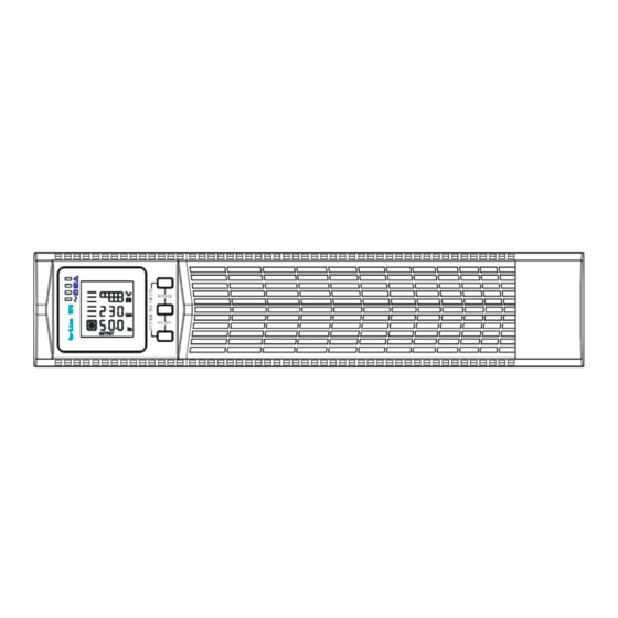
Operation T his chapter contains information on how to use the UPS, including front cover operation, operating modes, UPS startup and shutdown, transferring the UPS between modes, and configuring bypass settings, load segments, and battery settings. Control Cover Functions T he UPS has a three-button segmental LCD with backlight. It provides useful information about the UPS itself, load status, measurements, and settings (see Figure 16). - Page 20 Table 2 . Button function Button Function description S tart up combination ( ) Press and hold this key for more than half a second to turn on the UPS or to turn off the UPS. Shutdown/Rotating R T Press and hold this key for more than 2 seconds combination to circumrotate the LCD .
- Page 21 seconds B attery Voltage O nce per ● ★ ★ abnormal second warning B ypass mode M ain AC O nce Normal E liminate after ● ★ every two voltage in starting the UPS minutes bypass mode M ain AC high O nce voltage ★...
-
Page 22: Display Functions
● _indicator lights for a long time ★ _indicator flashes ▲ _the status of indicator depends on other conditions Display Functions A s the default or after 5 minutes of inactivity, the LCD displays the o utput parameters. T he backlit LCD automatically dims after 5 minutes of inactivity. Press a ny button to restore the screen. - Page 23 D isplay the status of the charger. W hen charger works normally, the corresponding icon will vary C harger-status dynamically and orderly. graphics w hen charger works abnormally, the section icon will keep flashing W hen UPS is in battery mode, the number icons charger-state...
-
Page 24: User Settings
D isplay the temperature of the inverter in the UPS. As following graphics shown: T emperature temperature of the inverter is 37℃. D isplay the voltage and frequency of the input. As the following I nput graphics shown: the input voltage is 210v, input frequency is 49.8Hz. - Page 25 Setting function(serial Setting procedure LCD display number) ① Enter the setting interface. Press and hold the function setting key for more than 2 seconds, then come to setting interface, the letters “ECO” will flash. ② Enter setting interface. Press and hold the function setting key for more than half a second(less than 2...
- Page 26 2 seconds, then come to setting interface ,short press the scroll key for more than half a second (less than 2 seconds) to select BPS setting, the letters “bPS” Bypass will flash. function ② Enter setting setting(2) interface. Press and hold the function setting key for more than half a second(less than 2...
- Page 27 more than half a second(less than 2 seconds), select the function setting, choose output voltage setting interface, at the moment, the letters “OPU” will flash. ② Enter the output voltage selecting interface. Press and hold the function setting for more than half a second(less than 2 seconds), then come...
- Page 28 function setting key for more B attery string than half a second(less than 2 number seconds), then come to setting type interface of battery, the letters setting ( 4) “bAt” will stop flashing. The numerical value below “bAt” will flash. Press and hold the scroll key for more than half a second (less than 2...
- Page 29 the function setting key more than half a second (less than 2 seconds). Now, the load shielding battery voltage setting is confirmed. ④ Exit from setting interface. Press hold function setting key for more than half a second (less than 2 seconds), exit from the setting interface and return to main interface.
- Page 30 ① Enter the setting interface. F requency Press and hold the function Converter setting key for more than mode setting 2 seconds, then come to (7) setting interface, Press and hold the scroll key more than half a second(less than 2 seconds), select the function setting, choose...
- Page 31 ① Enter the setting interface. P arameter Press and hold the function reset setting key for more than 2 factory seconds, then come to setting Setting ( 8) interface, Press and hold the scroll key for more than half a second(less than 2 seconds), select function...
- Page 32 instable, UPS will turn to battery mode at once. If the mains recovers,the UPS will transfer to line mode. If battery low alarm activates, the Battery indicator of flashes. If battery Mode voltage reaches low limit, UPS will turn off to protect the battery. UPS will auto-restart when the mains recover.
- Page 33 When UPS is plugged into line and not Standby turn on , the UPS will work in standby Mode mode to charge the battery. No indicator displays on this mode. U PS Turn on and Turn off Start up operation Turn on the UPS in line mode 1.
- Page 34 Configuring Battery Settings S et the UPS for the number of EBPs installed. T o ensure maximum battery runtime, configure the UPS for the correct n umber of EBPs, refer to Table 8 for the appropriate setting of battery numbers and type. Use the up and down scroll keys to select the number of battery strings according to your UPS configuration: T able 8 Battery number Configuration...
-
Page 35: Communication
5. Communication T his section describes the: ● Communication ports (RS-232 and USB) ● Connectivity cards ● Emergency Power-off (EPO) ● Load Segments ● UPSilon2000 Power Management Software S ee “Rear Covers” on page for rear cover diagrams for each model. Figure 17. - Page 36 : NOTE T he communication speed of the RS232 port is fixed at 2400 bps. RS-232 and USB Communication Ports T o establish communication between the UPS and a computer, connect your computer to one of the UPS communication ports using an appropriate communication cable (not supplied).
- Page 37 Connectivity Cards C onnectivity cards allow the UPS to communicate in a variety of n etworking environments and with different types of devices. The UPS has one available communication bay for the following connectivity cards: ● Web/SNMP Card - has SNMP and HTTP capabilities as well as monitoring through a Web browser interface;...
-
Page 38: Load Segments
emergency power-off function is activated. NOTE For Europe, the emergency switch requirements are detailed in Harmonized document HD-384-48 S1, “Electrical Installation of the Buildings, Part 4: Protection for Safety Chapter 46: Isolation and Switching.” EPO Connections Wire Function Terminal Wire Size Rating Suggested Wire Size 4–0.32 mm2 (12–22 AWG) 0.82 mm2 (18 AWG) - Page 39 Figure 22 Load Segments U PSilon2000 Power Management Software E ach UPS ships with UPSilon2000 Power Management Software. To begin installing UPSilon2000 software, see the instructions accompanying the Software Suite CD. N OTE Install UPSilon2000 power management software with the serial number attched on the cover of the CD .When running the monitor software , choose appropriate communication port.
-
Page 40: Ups Maintenance 4
6 UPS Maintenance This section explains how to: C are for the UPS and batteries R eplace Extended Battery Packs(EBPs) T est new batteries R ecycle used batteries or UPS UPS and Battery Care F or the best preventive maintenance, keep the area around the UPS clean and dust‐ free. - Page 41 Replacing RT UPS and EBPS 1. If the battery fault, the following steps are provided for modular unit to replace the new battery pack 2. Remove the front cover of the battery box. 3. Remove the connection cables between battery box and UPS. Release the screw of the baffle of the battery pack as the Fig.23 shows, then remove the baffle from the left or right.
- Page 42 Fig.24 Remove the battery park 5.Hold the middle of the new battery pack, insert it. Once install the new battery pack, make sure it is completely inserted into the chassis as fig shown. Fig.25 Installation for battery pack T esting New Batteries T o test new batteries: 1 .
-
Page 43: Recycling The Used Battery Or Ups
d ischarges the batteries for 10 seconds. The LED indicators of the front cover stop cycling when the test is completed. Recycling the Used Battery or UPS C ontact your local recycling or hazardous waste center for information on proper disposal of the used battery or UPS. -
Page 44: Model Specifications
S pecifications Model Specifications T his section provides the following specifications: C ommunication options M odel lists W eights and dimensions E lectrical input and output E nvironmental and safety B attery T able 10 Communication Options (All Models) Communication Bay available independent communication bay for connectivity cards Compatible... - Page 45 26.3 kg 440*572*86.5mm 33.0kg 440*696*86.5mm Model ( EBP) Dimensions (W *D *H) Weight 19.0 kg 440*430*86.5mm 1.5K- 24.0 kg 440*430*86.5mm 33.6kg 440*572*86.5mm 46.0 kg 440*690*86.5mm T able 14. Electrical Input (All Models) Nominal Frequency 50/60 Hz auto-sensing 45–55 Hz(50Hz)/55-65Hz(60Hz) before transfer to Frequency Range battery +5%,+10%,+15%,+25%( +25% by...
- Page 46 Table 17. Electrical Output (All Models) High Voltage Models 200/208/220/230/240V (voltage configurable or auto-sensing) Nominal Outputs 1000/1500/2000/3000 VA 0.9/1.35/1.8/2.7 kW Frequency 50 or 60 Hz, autosensing 108%±5%–150%±5%: Load transfers to Fault mode after 30 seconds. Output Overload 150%±5%–200%±5%: Load transfers to Fault mode after (Normal Mode) 300 ms.
- Page 47 Table 18. Electrical Output Connections ( A ll Models) Model Output Connections Output Cables (IEC C13-10A)*6 IEC320 C14-10A 1.5K- (IEC C13-10A)*6 IEC320 C14-10A (IEC C13-10A)*6 IEC320 C14-10A (IEC C19-16A)*1 IEC320 C20-10A IEC320 C14-10A (IEC C13-10A)*6 (IEC C19-16A)*1 IEC320 C20-10A Table 19. Environmental and Safety (All Models) 208/230/240 Vac Models EN 61000-2-2 EN 61000-4-2, Level 4...
- Page 48 Relative 0–90% noncondensing Humidity Operating Up to 3,000 meters (9,843 ft) above sea level Altitude Transit Altitude Up to 10,000 meters (32,808 ft) above sea level Audible Noise <55 dBA at 1 meter typical Leakage <1.5 mA Current Table 20. Battery Runtimes (in Minutes) at 100% Load (ALL Models) Model Internal Batteries + 1 EBP...
-
Page 49: T Roubleshooting
Rear Covers Figure 26. Figure 27. 8 Troubleshooting The following messages are the information that users would find on UPS when it meets some problems. Users can judge if the fault is caused by external factors and know how to deal with it by making full use of the information. - Page 50 When replace battery, contact Battery aged franchiser to get battery and relative assembly Didn’t press the Press the two keys at the same combination keys of time “on” UPS doesn’t UPS has no battery Connect UPS battery well, if startup after connected or battery battery voltage low, please turn pressing the ON...
Need help?
Do you have a question about the MEMO PLUS RT II (MP9100RTII-0.9) 1-3K and is the answer not in the manual?
Questions and answers