Table of Contents
Advertisement
Preface
Publish statement
Thank you for purchasing this series UPS.
This series UPS is an intelligent, Single phase in Single phase out,
high frequency online UPS designed by our R&D team who is with
years of designing experiences on UPS. With excellent electrical
performance, perfect intelligent monitoring and network functions,
smart appearance, complying with EMC and safety standards, The
UPS meets the world's advanced level.
Read this manual carefully before installation
This manual provides technical support to the operator of the
equipment.
Advertisement
Table of Contents

Related Manuals for KStar 6K-H


Summary of Contents for KStar 6K-H
- Page 1 Preface Publish statement Thank you for purchasing this series UPS. This series UPS is an intelligent, Single phase in Single phase out, high frequency online UPS designed by our R&D team who is with years of designing experiences on UPS. With excellent electrical performance, perfect intelligent monitoring and network functions, smart appearance, complying with EMC and safety standards, The UPS meets the world’s advanced level.
-
Page 3: Table Of Contents
Contents 1. Safety ..................1 Safety ................1 Symbol Description ............2 2. Product Introduction .............. 4 The appearance of the product ........4 The principle of the product ..........6 Product Category ............. 7 3. Installation ................8 Unpacking and inspection ..........8 Installation note ............... - Page 4 Parameter setting ............23 4.3.1 Mode setting ............23 4.3.2 Output voltage class setting ....... 24 4.3.3 Output frequency class setting ......25 4.3.4 Battery capacity setting ........26 4.3.5 Battery numbers setting ........27 4.3.6 Bypass Volt-HI setting ........28 4.3.7 Bypass Volt-Lo setting ........
-
Page 5: Safety
1. Safety This chapter mainly introduces the safety signs and security considerations of 6K/10K series high frequency online ups. Before any operation of equipment, you should read the content of this chapter carefully. Safety There exists dangerous voltage and high temperature inside the UPS. During the installation, operation and maintenance, please abide the local safety instructions and relative laws, otherwise it will result in personnel injury or equipment damage. -
Page 6: Symbol Description
Symbol Description The safety symbols cited in this manual are shown in table 1-1, which are used to inform readers of safety issues that should be obeyed when installation, operation and maintenance. Fig.1-1 Symbol meanings Safety Symbol Indication Attention Static discharge sensitive Electric shock There are three levers of safety grade: Dangerous, Warning and Attention. - Page 7 Description of Commonly Used Symbols Some or all of the following symbols may be used in this manual. It is advisable to familiarize yourself with them and understand their meaning:...
-
Page 8: Product Introduction
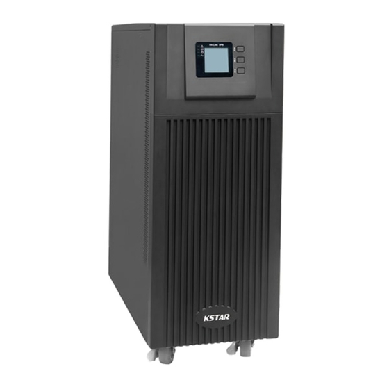
Product Introduction The appearance of the product 2.1.1 6K-H/ 6K-S Fig.1 6KVA(H) Front Panel view Fig.2 6KVA(H) Rear Panel view... - Page 9 Fig.3 6KVA(S) Front Panel view Fig.4 6KVA(S) Rear Panel view (See paragraph 4.2.1)
- Page 10 2.1.2 10K-H/10K-S Fig.5 10KVA(H)Front Panel view Fig.6 10KVA(H)Rear Panel view Fig.7 10KVA(S)Front Panel view Fig.8 10KVA(S)Rear Panel view...
-
Page 11: The Principle Of The Product
The principle of the product Fig. 2-1 UPS Principle Diagram 1. Input filter: Complete filtering the input AC utility power to provide the clean power for UPS. 2. AC/DC converter: Convert the filtered AC mains to DC and boost the DC for DC/AC inverter. -
Page 12: Product Category
Product Category UPS Type Remark Internal 16~20PCS(12V/PCS) batteries 6KVA Standard unit Internal 16~20PCS(12V/PCS) batteries 10KVA External 16~20PCS(12V/PCS) batteries Long 6KVA backup External 16~20PCS(12V/PCS) batteries unit 10KVA... -
Page 13: Installation
Installation Unpacking and inspection 1. Unpacking the UPS and check that whether it’s damaged during the transportation. If damaged or some parts missing, don’t start the machine and inform the carrier and franchiser. 2. Check the annex (please consult Appendix Table 2). 3. - Page 14 Fig.3-1 Correct power configuration INPUT L OUT PUT L LOAD INPUT N OUT PUT N Fig.3-2 Wrong power configuration...
-
Page 15: Ups Input And Output Connection
UPS input and output connection Minimum 10AWG copper wires are required for the 6KVA, and 8AWG for 10KVA,including input/output cables, battery cables. 1) Switch off all breakers before connecting cables 2) Remove the cover of the terminals, see Fig 2-3,following it to connect the cables Fig.3-3 I/O terminals connection CAUTION! -
Page 16: Parallel Card(Optional
Connection of the UPS communication cables 1)RS-232 cable provided in accessories can be used to connect the UPS with PC 2)Follow steps below to install SNMP (if purchased ): A. Remove the cover of SNMP slot at UPS rear panel and keep it for further use. -
Page 17: External Battery Conection(For Extend Model Only )
Connect all the outputs of the parallel UPS to one patch board before connect to the loads. See the picture as follows. Start one UPS in turn and set parameters through LCD: working mode: parallel mode; parallel ID: setting ID in sequence;... - Page 18 NOTICE: 1. Don’t mix batteries with different capacity, manufacturers and don’t mix brand new and old batteries, either. 2. The standard setting of the battery is 16 pcs and battery capacity is 65AH(charge current is 6A).When connecting with 18 pcs or 20 pcs battery, please start up the UPS under AC mode, connect to the computer to set up battery number and capacity, the UPS will follow battery capacity to distribute charge current automatically (Max charge current...
- Page 19 Warning: ★ Before installing battery, make sure that the UPS and breaker are all turned off. Remove all your metallic adornment such as finger ring, watch, and so on before connecting battery. ★ No anti-connection or short circuit between the battery anode and cathode forever.
-
Page 20: Panel Display, Operation And Running
Panel display, operation and running The operation is simple, operators only need to read the manual and follow the operation instructions listed in this manual, no need any special training. Start up and turn off UPS 4.1.1 Start up operation 1、Turn on the UPS in Line mode Once AC Power Cord is plugged in, the UPS will start automatically and the LCD display of the UPS will be lit on. -
Page 21: Faceplate Display
Remarks: When the UPS is turned off from the inverter mode, it will discharge DC Bus to 80V, then shut down completely; therefore, sometimes, it takes more several seconds to complete. Faceplate display 4.2.1 Faceplate display illumination Fig.4-1 Overview of the operating panel of the UPS ALARM LED BYPASS LED BATTERY LED... -
Page 22: Lcd Display
4.2.2 LCD display NOTICE! The display provides more functions than those described in this manual. There are 10 interfaces available in the LCD display: Interface ITEM Content Displayed Description Input Voltage & Frequency Bat.﹢ Voltage & Current Bat. - Voltage & Current Output Voltage &... - Page 23 1. When the UPS is connecting with the Utility or Battery at cold start mode, it shows as drawing below: (1) Operational Status and mode Operational Status and mode When the UPS at single mode, it shows “NOA” or “ECO”, but If the UPS at parallel mode, it shows “PAL” instead.
- Page 24 (4)Bat – voltage (Negative) (5)Output voltage 20% load per gird (6)Load (7) PFC/ Ambient temperature up, only shows the high temperature Internal temperature(down)...
- Page 25 (9)Software version & model ( 8 ) Alarm Code ( 10)Bus voltage...
- Page 26 1. If some of above interfaces have battery charging, it will display the charging information at the same time as shown below. Charging Boost Floating 2. Pressing “scroll” button, you may circulate all messages from the first one to the last one then returns back to the first one and vice versa. 3.
-
Page 27: Parameter Setting
Parameters setting The setting function is controlled by 3 buttons (Enter , Off ▲, On ▼): Enter ---goes into the setting page and value adjustment; Off ▲ & On ▼---for choosing different pages. After the UPS turn ON, press buttons & ▲ for 3 seconds and then goes into the setting interface page. -
Page 28: Output Voltage Class Setting
4.3.2 Output voltage class setting Output voltage setting (Note: Inside the broken-line is the flashing part.) When under the mode setting press On▼ or when under frequency setting press Off▲, it goes to the output voltage setting. The output voltage line flashes as in above picture. •... -
Page 29: Output Frequency Class Setting
4.3.3 Output frequency class setting Frequency setting (Note: Inside the broken-line is the flashing part.) When under the output voltage setting press On▼ or when under battery capacity setting press Off▲, it goes to the frequency setting. The frequency line flashes as in above picture. •... -
Page 30: Battery Capacity Setting
4.3.4 Battery capacity setting Battery capacity setting (Note: Inside the broken-line is the flashing part.) When under the frequency setting press On▼ or when under battery quantity setting press Off▲, it goes to the battery capacity setting. The battery capacity line flashes as in above picture. •... -
Page 31: Battery Numbers Setting
4.3.5 Battery quantity setting Battery quantity setting (Note: Inside the broken-line is the flashing part.) When under the battery capacity setting press On▼ or when under bypass voltage upper limit setting press Off▲, it goes to the battery quantity setting. The battery quantity line flashes as in above picture. •... -
Page 32: Bypass Volt-Hi Setting
4.3.6 Bypass Volt-Hi setting Bypass voltage upper limit setting (Note: Inside the broken-line is the flashing part.) When under the battery quantity setting press On▼ or when under bypass voltage lower setting press Off▲, it goes to the bypass upper limit setting. -
Page 33: Bypass Volt-Lo Setting
4.3.7 Bypass Volt-Lo setting Bypass voltage lower limit setting (Note: Inside the broken-line is the flashing part.) When under the bypass voltage upper limit setting press On▼ or when under parallel ID setting press Off▲, it goes to the bypass lower limit setting. -
Page 34: Buzzer Mute Setting
4.3.8 Buzzer Mute Setting Buzzers mute setting (Note:flashing part in dashed box) Press ON under bypass voltage lower limit setting or press OFF under the parallel ID setting can enter the buzzer setting. Now the setting status is flashing as the Figure 14 shows (note: on=mute; off= no mute). When press, it shows the mute cycle setting, the selection includes ON and OFF. -
Page 35: Parallel Id Setting
4.3.9 Parallel ID setting Parallel ID setting (Note: Inside the broken-line is the flashing part.) When under the bypass voltage lower limit setting press On▼ or when under parallel quantity setting press Off▲, it goes to the parallel ID setting. The parallel ID flashes as in above picture. -
Page 36: Parallel Quantity Setting
4.3.10 Parallel quantity setting Parallel quantity setting (Note: Inside the broken-line is the flashing part.) When under the parallel ID setting press On▼ or when under parallel redundancy quantity setting press Off▲, it goes to the parallel quantity setting. The parallel quantity flashes as in above picture. •... -
Page 37: Parallel Redundancy Quantity Setting
4.3.11 Parallel redundancy quantity setting Parallel redundancy quantity setting (Note: Inside the broken-line is the flashing part.) When under the parallel quantity setting press On▼, it goes to the parallel redundancy quantity setting. The parallel redundancy quantity flashes as in above picture. •... -
Page 38: Display Messages/Record
Display Messages/ Records This section lists the event and alarm messages that the UPS might display. The messages are listed in alphabetical order. This section is listed with each alarm message to help you troubleshoot problems . 4.4.1 Operational Status and Mode(s) Note:“X”... -
Page 39: Modes And Alarm Information
Item UPS Alarm Warning Buzz Bypass Thyristor Beep continuously Fault LED lit short Bypass Thyristor Beep continuously Fault LED lit broken Fuse broken Beep continuously Fault LED lit Parallel relay fault Beep continuously Fault LED lit Fan fault Beep continuously Fault LED lit Reserve Beep continuously... - Page 40 Item UPS Alarm Warning Buzz Bypass over current Once per second BPS LED blinking Overload Once per second INV or BPS blinking No battery Once per second BATTERY blinking Battery under voltage Once per second BATTERY blinking Battery Once per second BATTERY blinking pre-warning Internal...
-
Page 41: Maintenance
Maintenance UPS use in the appropriate environment (see 3.2 installation considerations) can be free maintenance or less maintenance. 5.1 Battery maintenance 1. It is recommended that the batteries are manually charged or discharged Once every three or four months if the UPS has not been used for a long time or the power is long-term uninterrupted. -
Page 42: Troubleshooting And Performance Of The Product
Troubleshooting and performance of the product 1. In case the UPS can not work normally, it might be wrong in installation, wiring or operation. Please check these aspects first. If you need help, contact our service department, the following messages should be provided for analysis: ... -
Page 43: Emc Standard/Safety Standard
Press the ON key Press and hold the ON key for more for a short time than one second to start the UPS UPS has no battery No AC power, UPS connected or Connect UPS battery well, if battery can’t startup after battery voltage low voltage low, please turn off UPS and pressing the ON... -
Page 44: Product Performance
Product Performance Type 6 kVA 10 kVA Capacity 4.8 kW 8 kW Input Single phase & Ground ≥ 0.99(input THDV ≤1%) Power factor Rated voltage 220VAC / 230VAC / 240VAC Rated frequency 50Hz/60Hz Automatically selected Voltage range 120~276Vac Frequency range 45~65Hz 220Vac max:default +25% (+10% ,+15%,... - Page 45 ±0.1% (stand alone) Frequency regulation ±0.25% (parallel operation) Utility mode:tracking mains frequency Frequency Battery mode:50Hz/60Hz 1Hz/s (stand alone) Frequency track speed 0.5Hz/s (parallel operation) 105 %~ 110 %,lasts 1 hour load capacity (Mains, drop a 110%~125%,lasts 10 minutes level in battery 125%~150%, lasts 1 minute mode)...
- Page 46 Max input voltage 320Vac,1 hour(static) Conduction :IEC 62040-2 Radiation :IEC 62040-2 Harmonics :IEC 62040-2 IEC 62040-2 > 2MΩ(500Vdc) Isolation resistance Isolation intension 2820Vdc, <3.5mA,1min Meeting IEC60664-1 1.2/50uS+8/20uS Surge 6kV/3kA. Protection IP20 Parallel circumfluence 1+1≤8%,N+1≤3% Parallel equal current 1+1≤8%,N+1≤10% ◆ Work Environment Model 6kVA-10kVA series 0°C~40°C...
-
Page 47: Appendix 1 Rs232 Communication Port Definition
Appendix I RS232 communication port definition Definition of Male port: Connection between PC RS232 port and UPS RS232 port: PC RS232 port UPS RS232 port Pin 2 Pin 2 UPS send,PC receive Pin 3 Pin 3 PC send,UPS receive Pin 5 Pin 5 ground Available function of RS232:... -
Page 48: Appendix 2 Shipping List
Appendix II Shipment list Items Description Quantity Unit 《UPS User Manual》 Drier Calibration CD-ROM Intelligent monitoring CD-ROM RS232 Cable Appendix III Options Items Name Description Remark Parallel card Parallel function (Parallel cable) optional Remote monitoring SNMP card UPS operating status Dry contact card Maintenance...
Need help?
Do you have a question about the 6K-H and is the answer not in the manual?
Questions and answers