Sign In
Upload
Download
Table of Contents
Contents
Add to my manuals
Delete from my manuals
Share
URL of this page:
HTML Link:
Bookmark this page
Add
Manual will be automatically added to "My Manuals"
Print this page
×
Bookmark added
×
Added to my manuals
Manuals
Brands
KStar Manuals
UPS
6kVA
Operation manual
KStar 6kVA Operation Manual
Single phase
Hide thumbs
1
2
3
Table Of Contents
4
5
6
7
8
9
10
11
12
13
14
15
16
17
18
19
20
21
22
23
24
25
26
27
28
29
30
31
32
33
page
of
33
Go
/
33
Contents
Table of Contents
Troubleshooting
Bookmarks
Table of Contents
Safety Instruction
Table of Contents
1 Product Introduction
Application
Product Range
System Principle Diagram
Features
Product Overview
Product View
LCD Operation Instruction
Display Instruction
Rear Panel Instruction
2 Installation
Unpack Checking
Installation Procedure
Installation Note
Installation
Connection of Parallel System
3 Operation
Working Modes
AC Mode
Bypass Mode
Battery Mode
ECO Mode
Operation
Power on
Start
System Parameter Setting
Inverter Power off
Manual Battery Testing
Power off
Working Mode and Transferring
Goes to Bypass Mode Due to over Temperature
Normal Mode to Battery Mode
Output Short Circuit
Transfer to Bypass if Overload
UPS Monitoring
LCD Operation Menu
Main Menu Switching
Priority of Info Displayed on the LCD
Submenu Switching
4 Maintenance
Fan Maintenance
Battery Maintenance
Visual Checking
UPS Status Checking
Function Checking
5 Trouble Shooting
A1 USB Communication Port Definition
A2 Specification
A3 Option
A4 UPS Message Table
Advertisement
Quick Links
1
Lcd Operation Instruction
2
Ups Status Checking
3
Trouble Shooting
4
A4 Ups Message Table
Download this manual
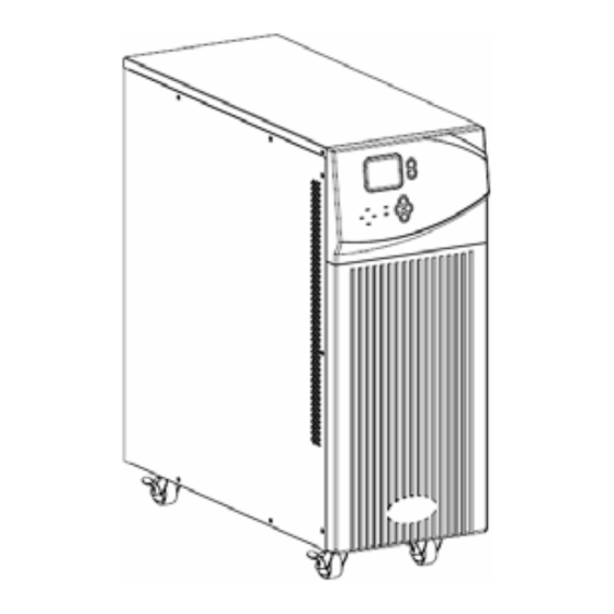
Uninterruptible Power Systems
single phase 6/10KVA
Operation Manual
Table of
Contents
Previous
Page
Next
Page
1
2
3
4
5
Advertisement
Table of Contents
Need help?
Do you have a question about the 6kVA and is the answer not in the manual?
Ask a question
Questions and answers
Related Manuals for KStar 6kVA
UPS KStar 6K-H Manual
6k/10k series (48 pages)
UPS KStar 600 User Manual
(8 pages)
UPS KStar 600 Operation Manual
(7 pages)
UPS Kstar 10kVA Operation Manual
Single phase (33 pages)
UPS KStar MEMO PLUS RT II (MP9100RTII-0.9) 1-3K User Manual
1kva to 3kva 0track-tower conversion (51 pages)
UPS KStar YDC9300-0.8 User Manual
(39 pages)
UPS KStar GP800 User Manual
(38 pages)
UPS KStar 1K User Manual
Line interactive sinewave-ups (20 pages)
UPS KStar UDC9101RTS Operation Manual
Memopower rt series (21 pages)
UPS KStar UDC9101S One User Manual
Memopower udc one series (24 pages)
UPS KStar YDC9300-RT Series Manual
(30 pages)
UPS KStar YMK3300 Series Manual
(77 pages)
UPS KStar YDC9300-B Operation Manual
(45 pages)
UPS KStar YDC9300-RT Operation Manual
(45 pages)
UPS KStar YDC9300-RT Operational Manual
(45 pages)
UPS KStar HIP3300E Operation Manual
(78 pages)
This manual is also suitable for:
10kva
Table of Contents
Save PDF
Print
Rename the bookmark
Delete bookmark?
Delete from my manuals?
Login
Sign In
OR
Sign in with Facebook
Sign in with Google
Upload manual
Upload from disk
Upload from URL


Need help?
Do you have a question about the 6kVA and is the answer not in the manual?
Questions and answers