Table of Contents
Advertisement
Allrightsreserved.
Theinformationinthisdocumentissubjecttochangewithoutnotice.
Publishstatement
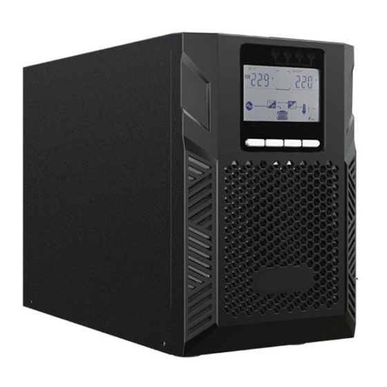
ThankyouforpurchasingthisseriesUPS.
ThisseriesUPSisanintelligent,singlephaseinsinglephaseout,highfrequency
onlineUPSdesignedbyourR&Dteamwhoiswithyearsofdesigningexperienceson
UPS.Withexcellentelectricalperformance,perfectintelligentmonitoringand
networkfunctions,smartappearance,complyingwithEMCandsafetystandards,The
UPSmeetstheworld'sadvancedlevel.
Readthismanualcarefullybeforeinstallation
Thismanualprovidestechnicalsupporttotheoperatoroftheequipment.
1
Advertisement
Table of Contents


Need help?
Do you have a question about the UDC9101S One and is the answer not in the manual?
Questions and answers