Table of Contents
Advertisement
Quick Links
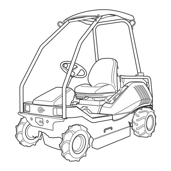
Ride-on Brushcutter
CM 230
OPERATOR'S MANUAL
* Read this manual completely before operating or maintaining this machine.
Failure to follow safety precautions could result in serious injury or death.
* Keep this manual for future reference for you and for all those who operate
and maintain this machine.
October 2005, 5317 5201 000 01
CHIKUSUI CANYCOM, INC.
90-1 Fukumasu, Yoshii-machi,
Ukiha city, Fukuoka, Japan 839-1396
Tel. 81-(0)943-75-2195 Fax. 81-(0)943-75-4396
Advertisement
Table of Contents

Related Manuals for CanyCom CM 230


Summary of Contents for CanyCom CM 230
- Page 1 Ride-on Brushcutter CM 230 OPERATOR'S MANUAL * Read this manual completely before operating or maintaining this machine. Failure to follow safety precautions could result in serious injury or death. * Keep this manual for future reference for you and for all those who operate and maintain this machine.
- Page 2 CHIKUSUI CANYCOM, INC. ■Sales Headquarters 0943(75)2195 FAX (75)4396 ■Osaka Center 0790(42)6031 FAX (42)6035 ■Foreign Trade Center 03(3552)6277 FAX (3552)6288 ■Hiroshima Center 0824(34)5996 FAX (34)5997 ■Tokyo Center 03(3552)6255 FAX (3552)6288 ■Matsuyama Center 089(983)2701 FAX(983)5749 ■Sendai Center 022(281)1255 FAX (281)3141 ■Fukuoka Center 0943(76)2583 FAX (75)5126 ■Saitama Center...
-
Page 3: Table Of Contents
Contents Introduction Introduction …………………………………………………… 1 Safety Rules Safety Declaration …………………………………………… 2 Safety Operation (B71.4) …………………………………… 2 Training ……………………………………………………………………………… 2 Preparation …………………………………………………………………………… 2 Operation ……………………………………………………………………………… 3 Maintenance and Storage …………………………………………………………… 4 Rules for Safe Operation and Work ………………………… 5 Safety Precautions Before Operation ……………………………………………… 5 Do Not Start, Accelerate, Turn, or Brake Quickly …………………………………... - Page 4 Recommended Oil ………………………………………………………………… 19 Inspecting Engine Oil ……………………………………………………………… 19 Preparation Details of Attachments ………………………………………20 Preparation for Starting ………………………………………20 Adding Grease and Oil …………………………………………………………… 20 Inspecting Engine Oil ……………………………………………………………… 21 Inspecting HST Oil ………………………………………………………………… 22 Checking Tire Pressure ………………………………………………………… 23 Checking Rotary Height ………………………………………………………… 23 Checking Grass Chute Cover ……………………………………………………...
- Page 5 Maintenance Periodic Check Sheet ………………………………………44 Fuel / Grease / Lubricant / Fluid Chart …………………… 47 Consumable (Replacement Parts) Chart …………………48 Engine …………………………………………………………49 Inspecting, Adding and Replacing Engine Oil ………………………………… 49 Replacing Engine Oil Filter ……………………………………………………… 51 Cleaning and Replacing Air Cleaner …………………………………………… 52 Cleaning Cooling System …………………………………………………………...
- Page 6 Inspecting and Adjusting Rotary Driving V-Belt………………………………… 71 Inspecting and Adjusting Rotary Cutter Brake ………………………………… 71 Lubrication and Greasing ……………………………………73 Disposal of Waste ……………………………………………73 Storage Maintenance After Use ……………………………………… 74 Maintenance After Use in Normal Conditions ………………………………… 74 Maintenance After Use in Cold Season ………………………………………… 74 Long-Term Storage……………………………………………...
-
Page 7: Introduction
Introduction Introduction Introduction Please read this manual to completely understand the machine operation and maintenance procedures before using the machine. Following this manual’s instructions may help avoid human injury and mechanical damage. This machine has been designed and manufactured with due regard to safety. Operators and service staff however, should also take safety precautions when working with this machine. -
Page 8: Safety Rules
1. Check the operating area before deciding the accessories and attachments required for safe operation. Only use accessories and attachments approved by CHIKUSUI CANYCOM, INC. (hereafter called “Manufacturer”). 2. The operators of the machine must wear proper protective clothing including safety helmets, protective glasses, ear plugs, etc. -
Page 9: Operation
Safety Rules smoke near machine during refueling. c. Do not add or remove fuel indoors. 5. Confirm that the seat-adjusting device for the operator, safety switches, and shields are installed and function properly before using machine. If they do not function properly, do not operate the machine. -
Page 10: Maintenance And Storage
Safety Rules Maintenance and Storage 1. Before maintaining or storing the machine, disconnect the running and cutting systems from their driving units, apply the parking brake, and pull the ignition plug cord out. Before storing the machine, adjust, clean, and repair the movable parts. 2. -
Page 11: Rules For Safe Operation And Work
Safety Rules Rules for Safe Operation and Work This chapter shows the general safety precautions to be observed during driving or operation. Try to carry out driving or operation safely by being sure to follow the safety instructions in other chapters as well. Safety Precautions Before Operation Wear proper clothes and protective... -
Page 12: Do Not Start, Accelerate, Turn, Or Brake Quickly
Safety Rules Do Not Carry Passengers on This Machine This machine has one seat only: the operator’ s seat. It is extremely dangerous to drive this machine with passengers. Never allow a person or persons other than the operator to ride on the machine. -
Page 13: Safety Precautions When Operating
Safety Rules Reduce Driving Speed going Downhill Stop before driving downhill, shift the auxiliary speed change lever to the “LOW” speed position, and drive downhill at reduced speed. CM-02-030 Safety Precautions When Operating Secure Area (No Admittance) During Operation Post notice boards before that operation to show that job site is under operation. -
Page 14: Precautions When Parking
Safety Rules Precautions on Crumbling Ground Beware of driving in trenches and on banks. There is a danger of the ground crumbling due to the machine weight. When travelling on soft ground, drive slowly and safely. CM-03-040 Avoid Driving Across Slopes Always travel straight up or down a slopes. -
Page 15: Precautions When Performing Maintenance
Safety Rules Avoid Parking on Slopes Avoid parking the machine on slopes. If there are no other options, apply the parking brake securely and block the wheels at the lower end . CM-04-030 Precautions When Performing Maintenance Never Carry Out Maintenance with Engine Running Do not carry out maintenance with the engine running. -
Page 16: Inclination Measuring Gage
Safety Rules Inclination measuring Gage FOLD ALONG APPROPRI ATE LINE EXAMPLE:COMPARE SLOPE WITH FOLDED EDGE 5317M-0204-010 Copy this page. Do not remove from this manual. -10-... -
Page 17: Warning Words Used In This Manual
Safety Rules Warning Words Used in This Manual To indicate the level of danger (or the degree of the failure), the following four signal words are used to identify the safety messages in this manual. Their meanings are as follows: Signal word Meaning Indicates an imminently hazardous situation which, if not... -
Page 18: Explanation Of Warning Labels On The Machine
Safety Rules Explanation of Warning Labels on the Machine NOTE *Replace these labels immediately if they have been removed, have fallen off, or have become illegible. Use the part numbers on the label to order replacement labels from dealer. 5317M-0206-010 -12-... - Page 19 Safety Rules 1 2 3 4 5 6 7 5317M-0206-020-E -13-...
- Page 20 Safety Rules 5316 5003 000 5316 5004 000 5317M-0206-030-E -14-...
-
Page 21: Specifications
Specifications Specifications Specifications * Read and understand specifications before using this product. Model CM230 Machine weight Overall length 2170 Overall width 1110 Overall height 1840 Wheel base 1460 Front Tread Rear Minimum freeboard Model Air-cooled 4-cycle gasoline Type KAWASAKI FH680V Cylinder (Bore X Stroke) 75.2 ×... - Page 22 Specifications Model CM230 Main speed shift HST (Hydrostatic) drive Steering device Rack and pinion type round steering wheel Brake type Internal expanding type brake Front wheel 4.00-7 Tire Rear wheel 17 × 8.00-8 Blade type Free knife & stepped stay Cutter blade width Cutter blade height 30 ~ 11...
-
Page 23: Gasoline And Oil
Gasoline and Oil Gasoline and Oil Explanation of Gasoline Recommended Gasoline * Use fresh lead-free gasoline. In order to prevent knocking, use gasoline with a octane number higher than 87. If knocking still occurs, replace the gasoline brand or with an even higher octane number composition. * Do not use fuel containing alcohol. -
Page 24: Refueling Fuel Tank
Gasoline and Oil Refueling fuel tank * Gasoline may cause fires or explosions leading to serious injuries or death. Always refuel the fuel tank outdoors in open air. * When adding fuel, keep open flames (lighted cigarettes, etc.) away from fuel and engine. -
Page 25: Explanation Of Oil
Gasoline and Oil Explanation of Oil Recommended Oil Use the oil specified by the manufacturer as show in the list of specifications for oil, grease, fuel, and water. (See Page 47) Inspecting Engine Oil * Always stop the engine before checking the engine oil. Inspection 1. -
Page 26: Preparation
Preparation Preparation Details of Attachments Before using the machine the first time after purchasing it, check that all the attachments shown below are available. Part name Quantity Remarks Operator's manual This manual Instruction manual for engine Plug wrench Closed wrench Preparation for Starting Before using the machine the first time after purchasing it, perform the following inspections and checks. -
Page 27: Inspecting Engine Oil
Preparation Inspecting Engine Oil * Always stop the engine before checking the engine oil. Inspection 1. Park machine on level ground. Filler cap 2. Open the engine cover. 3. Pull out the oil gauge. Clean the gauge with clean cloth. Reinsert to measure oil level. NOTE * Check the amount of oil before the engine is started or at least 10 minutes or more after... -
Page 28: Inspecting Hst Oil
Preparation Inspecting HST Oil * Always stop the engine before checking the engine oil. * Maintain proper oil level to prevent air from entering system and disrupting smooth operation. Inspection Oil level guage 1. Park machine on horizontal surface. 2. Open the engine cover. 3. -
Page 29: Checking Tire Pressure
Preparation Checking Tire Pressure 1. Check the pressures of the front and rear wheel tires. If they do not meet the standard value, adjust them. In order to prevent flat tires, the boundary zones between the tires and hubs outside and inside the wheels are filled with a tire protective agent (Ultraseal). -
Page 30: Checking Grass Chute Cover
Preparation Checking Grass Chute Cover 1. Confirm that the safety pins for stopping the opening/closing movement of the grass chute cover are securely inserted. 5317M-0502-050-E -24-... -
Page 31: Operation
Operation Operation Observance of Safety First When using the machine, observe the "Safety Rules". For Use of ROPS * Never perform cutting work when the ROPS has been removed. A turnover during cutting work in an inclined area is extremely dangerous. A machine without the ROPS installed does not meet the requirements of OSHA1928.52. -
Page 32: Component Names And Functions
Operation Component Names and Locations Location FORWARD REVERSE 5317M-0603-010-E -26-... -
Page 33: Component Names Functions And Operations
Operation Component Names, Functions and Operations 1 Main switch ………………………… Start or stop engine with this switch. * When the machine is not used remove and keep the key. 2 Accelerator lever … … … … … … … Increases and decreases engine speed. 3 Choke lever …………………………... -
Page 34: How To Drive
Operation How to Drive How to Adjust Seat Adjustment of seat hardness Seat longitudinal position-adjusting lever 1. Pull the seat hardness-adjusting lever up and to right or left to obtain proper hardness. 2. After obtaining the proper hardness, return the lever to the original position and fix it securely. -
Page 35: Starting
Operation Starting * Start engine only in well ventilated area to avoid inhaling poisonous exhaust gases. * Never turn the main switch to the "START" position when the engine is running. This may damage the engine and starter motor. * Do not rotate the starter motor longer than 15 seconds. If the engine does not start within 15 seconds, return the main switch to the "OFF"... - Page 36 Operation 3. Release your foot from the HST pedal. HST pedal 5317M-0604-010-E 4. Confirm that the speed change lever is in the Speed change lever "NEUTRAL" position. 5317M-0604-040-E 5. Shift the accelerator lever to the intermediate Accelerator lever position between the “LOW” and “HIGH” positions.
- Page 37 Operation 7. Depress the foot brake pedal. Parking brake lock lever NOTE * The engine will start only when the operator is sitting on the seat and the brake pedal is depressed. Under these conditions, the safety switch is disengaged. Brake pedal 5314M-0602-010-E 8.
- Page 38 Operation 12. Fix the brake pedal in its depress position Parking brake lock lever using the parking brake lock lever. 13. Warm up engine without loads, referring to the following table. Air temperature Recommended warming-up time Over 0°C About 10 minutes Brake pedal 5314M-0602-010-E 0°C to -10°C...
-
Page 39: Operating
Operation Operating * Keep people away from machine during operation. * Always check the operation area around machine before starting machine, and start it machine slowly. * Always check the operation area around machine before turning machine. * Avoid sudden starts, accelerations, and turns, to prevent the operator from being thrown off machine or machine slipping and turning over. - Page 40 Operation 4. Firmly shift the speed change lever to the Speed change lever “LOW” side. 5317M-0604-050-E 5. Depress the HST pedal slowly to start the machine. When driving the machine forward, FORWARD depress the front side pedal. When driving backward, depress the rear side pedal. REVERSE HST pedal 5317M-0604-020-E...
-
Page 41: Stopping
Operation Stopping * Avoid sudden stops to prevent operator from being thrown off the machine and the machine slipping and turning over. * Select hard and level ground for stopping or parking the machine. Do not stop or park the machine in dangerous areas. * Avoid parking machine on inclined ground. - Page 42 Operation 3. Depress the brake pedal to firmly stop the Parking brake lock lever machine. 4. Lock the brake pedal, using the parking brake lock lever. Brake pedal 5314M-0602-010-E 5. Confirm that the blade clutch lever is Blade clutch lever positioned at “OFF”.
-
Page 43: How To Perform Work
Operation How to Perform Work Checking Cutting Blades Before starting work, check the cutting blades. Refer to the procedure in "Check and replacement of cutting blade" shown on page 69. Adjusting Blade Height 1. Adjust cutting height with the blade height Rotary height adjusting switch adjusting switch. -
Page 44: Working Procedure
Operation Working Procedure * Do not insert hands or feet under the cover of the rotating cutting blades. * Keep people away from machine during cutting work. * Perform cutting work with caution to avoid to hurting people and animals and damaging crops, buildings, automobiles, and other objects or structures with stones or other object thrown by the machine. - Page 45 Operation * Immediately stop the engine to remove any foreign matter caught in the cutting blades. Foreign matter may unbalance the rotary blade and cause vibrations and failure. 1. Confirm that the grass chute cover is closed. Cover Grass chute 5314M-0608-020-E 2.
- Page 46 Operation 4. If necessary, change the blade height by Rotary height adjusting switch adjusting the rotary height adjusting switch. 5314M-0602-030-E 5. Shift the accelerator lever to “HIGH” and Accelerator lever increase the rotation speed of the engine. 5314M-0603-010-E 6. Shift the auxiliary speed change lever to Speed change lever "LOW", and start the cutting work at low running speed.
-
Page 47: Transportation
Operation Transportation Loading * When loading and unloading the machine onto or off a truck, follow these procedures: * Keep people away from the machine, truck, and running boards while loading or unloading the machine. * Do not turn on the running boards. The machine may drop off the running boards. -
Page 48: Lifting By Crane
Operation Lifting by Crane * Crane operations and slinging work should be performed by qualified operators. * Use lifting wire ropes and shackles with sufficient strength to hold the weight of the machine. * Carefully consider the machine’s center of gravity and balance while lifting. Use installed four hoisting lugs to securely sling the machine and maintain horizontal balance when lifting. -
Page 49: Emergency Transferring
Operation Emergency Transferring * Do not use this method to transfer the machine from an inclined area. When the machine cannot be moved by normal means due to engine trouble or other factors, transfer it using this procedure. 1. Shift the speed change lever to “NEUTRAL”. Speed change lever 5314M-0604-040-E 2. -
Page 50: Maintenance
○ ○ noise. The rotation speeds at the idling and maximum Please contact your rotation at no-load should meet the specified Canycom distributor ○ ○ values, respectively, and both rotation speeds should be constant. Engine speed When accelerating the engine, the movement of the accelerating lever should be smooth, the ○... - Page 51 Maintenance Timing Item Action Remarks The amount of oil should be proper and no Action / Replacement ○ ○ ○ noticeable dirt should be found in oil. (see page 52) Lubricating system There should be no noticeable oil leak in the ○...
- Page 52 Maintenance Timing Item Action Remarks Brake action should stop the machine under ○ ○ normal driving conditions. Brake The play of the pedal should be proper. ○ ○ There should be no damage in the rods, links, Rod, link, and or wires, and no looseness in their mounting ○...
-
Page 53: Fuel / Grease / Lubricant / Fluid Chart
Maintenance Fuel / Grease / Lubricant / Fluid Chart Reference Item Timing Recommendation Amount page As necessary. Gasoline See page Fuel 30.0 liter Add : Check daily and Engine oil add as necessary. API class : SE higher #20~#30 Replace : SAE class: 10W-30 1st time after 8 See page... -
Page 54: Consumable (Replacement Parts) Chart
Maintenance Consumable (Replacement Parts) Chart Item Part No. Replacement Quantity Reference Engine Engine oil filter cartridge Replace if defective See page 51 Paper element Replace if defective See page 52 Foam element Replace if defective See page 52 Throttle wire 53100102000 Replace if defective Choke wire 53100105000 Replace if defective... -
Page 55: Engine
Maintenance Engine * Always stop engine before performing maintenance. * Perform maintenance after engine has cooled to reduce risk of burns from high engine temperatures. Inspecting, Adding, and Replacing Engine Oil * Allow oil to cool before inspecting, adding or replacing to reduce risk of burns. * Properly dispose of waste oil after removing from engine. - Page 56 Maintenance 4. Add the specified engine oil when the oil level is lower than range indicated by "A" on the oil level gage. 5. Replace the present engine oil with new oil if present oil is noticeably dirty or has deteriorated into poor viscosity.
-
Page 57: Replacing Engine Oil Filter
Maintenance Replacing Engine Oil Filter 1. Drain the engine oil. Mating surface “B” 2. Remove the oil filter cartridge, using an oil filter wrench. 3. Clean the mating surface “B” for mounting the Filter cartrige filter cartridge to the engine. 4. -
Page 58: Cleaning And Replacing Air Cleaner
Maintenance Cleaning and Replacing Air Cleaner * Check and clean the air cleaner periodically (every 25 hours for the foam element and every 50 hours for the paper element). Severely dirty elements may cause poor starting, insufficient output, and reduce engine life. If there are any defects in the elements, replace them with new ones. -
Page 59: Cleaning Cooling System
Maintenance Cleaning Cooling System 1. Remove the air cleaner cover, fan cover guard, and fan cover. Fan cover guard 2. Clean the fan housing and cooling fan using compressed air. Fan cover Fan housing Cooling fan 5317M-0704-010-E 5317M-0704-010-E Inspecting, Cleaning, and Replacing Ignition Plug * Avoid pulling the cord when removing the ignition plug cap. - Page 60 Maintenance 2. Remove the ignition plug with a plug wrench. Degree of burning Damage Breakage 3. Check for the following defects, or damage. Replace plug if damaged or cannot be cleaned. * Damage to insulator * Worn electrodes * Carbon deposits on electrodes Wear, carbon deposit * Damage or breakage of gasket * Burned insulator...
-
Page 61: Fuel System
Maintenance Fuel System * Always stop the engine before performing maintenance. Draining Fuel * Keep flames and flammable away from fuel. * Avoid spilling fuel. Immediately wipe up spilled fuel. * Properly dispose of waste fuel after removing from machine. 1. -
Page 62: Inspecting Fuel Filter
* A black fuel filter is clogged and may prevent fuel from reaching the engine, causing the engine to stop. * A CHIKUSUI CANYCOM authorized dealer should replace the fuel filter to reduce the risk of fire at the fuel filter-fuel hose joint. -
Page 63: Hydraulic System
Maintenance Hydraulic System * Always stop the engine before performing maintenance. * Allow oil and system parts to cool before performing maintenance to reduce risk of burns. * Properly dispose of waste hydraulic oil after reaming from machine. Inspecting, Adding, and Replacing HST Oil * Maintain proper oil level to prevent air from entering system and disrupting operation. - Page 64 Maintenance Adding Oil Filler cap 1. Remove the cap from the hydraulic oil filler port. 2. Add the specified hydraulic oil to the oil filler port. 3. Check the oil level gage and confirm that the system is filled with the specified amount of the hydraulic oil.
-
Page 65: Replacing Hst Oil Filter
Maintenance Replacing HST Oil Filter 1. Drain the oil from the oil tank. 2. Remove the oil hose connecting to the oil tank. 3. Remove the tank cover and replace the oil filter Oil tank connection hose inside the tank with a new one. 4. -
Page 66: Running System
Maintenance Running System * Always stop the engine before performing maintenance. Inspecting, Adding, and Replacing Transmission Oil * Allow oil and parts to cool before performing maintenance to reduce risk of burns. ` Properly dispose of waste oil after removing from machine. Inspecting Oil Oil level check bolt 1. -
Page 67: Replacing Differential Oil And Knuckle Oil
Maintenance Replacing Oil 1. Position a vessel suitable for receiving the drained oil under the drain plug. 2. Remove the drain plug and drain the present oil from the draining port. 3. Attach the drain plug to the draining port. Drain plug 4. -
Page 68: Inspecting And Adjusting Driving V-Belt
Maintenance Inspecting and Adjusting Driving V-Belt NOTE * Perform maintenance without changing V-belt tension. Adjust V-belt tension only after it slips. Inspecting V-belt Engine pulley Visually check each V-belt for damage. Replace any damaged V-belt. Driving V-belt Adjusting V-belt HST pulley Adjust the adjusting nut to make the spring length 92 mm. -
Page 69: Checking Tire Pressure
Maintenance Checking Tire Pressure Check the pressures of the front and rear wheel tires. If they do not meet the standard values, adjust them. To prevent flat tires, the boundaries between the tires and hubs outside and inside of the wheels are filled with a tire protective agent (Ultraseal). -
Page 70: Electrical Equipment
Maintenance Electrical Equipment * Always stop the engine and turn the main switch to "OFF" before performing maintenance. Inspecting Battery Electrolyte and Adding Water * Keep flames and flammable material away from battery. * Stop using battery when the electrolyte level is below the lower limit to avoid shortening battery life and reduce risk of explosion. -
Page 71: Charging Battery
Maintenance Charging Battery * Remove the battery from machine before charging. * Keep flames and flammable material away from battery to avoid fire caused by hydrogen gas. * Do not charge the battery when the battery electrolyte level is lower than the "LOWER LEVEL"... - Page 72 Maintenance 1. Remove the battery from the machine. 2. Charge the battery according to the instructions in the manual of the battery to be used. 5116M-0509-040 Inspecting and Replacing Fuses * When a fuse has blown, examine the cause first. Do not replace the fuse before correcting the cause.
-
Page 73: Electric Circuit Diagram
Maintenance Electric Circuit Diagram HOURS 4 3 2 1 5317M-0708-020E -67-... -
Page 74: Cutting Unit
Maintenance Cutting Unit * Always stop the engine before performing maintenance. * Allow parts to cool before performing maintenance to reduce risk of burns. Opening Grass Chute Cover * Open grass chute cover only for inspection. * Avoid catching hands and fingers in grass chute cover when opening. * Close grass chute cover after inspecting and return the opening/closing lock pins to their original positions. -
Page 75: Inspecting And Replacing Cutting Blades
Maintenance Inspecting and Replacing Cutting Blades * Immediately replace broken cutting blades to avoid unbalanced rotation in the rotary cutter causing irregular vibrations and failure. * Always replace blades in pairs to avoid unbalanced rotation causing irregular vibrations and failure. * Always check the cup square neck bolt wear and replace if heavily worn. - Page 76 Maintenance Cup square neck bolt 5317M-0709-040-E Replacement 1. Open the grass chute cover. 2. To prevent the rotation of the rotary cutter, insert a high strength bar, such as a screwdriver, into the hole “I” of the blade stay. First, shift the failed blade, turning it around the Cap “N”...
-
Page 77: Inspecting And Adjusting Rotary Driving V-Belt
4 seconds when shifting the cutting blade clutch lever to "OFF". When it does not stop, check the wear of the brake lining. If the worn lining is less than 20 mm in thickness, ask a CHIKUSUI CANYCOM dealer to replace the brake lining. 5314M-0708-030-E -71-... - Page 78 Maintenance Adjusting Rotary Cutter Brake Adjustment nut “G” When the rotary cutter does not stop within about Blade pulley 4 seconds after shifting the cutting blade clutch lever to "OFF", and when the rotary stopper is Spring “F” replaced, adjust the rotary cutter brake according When shifting the blade clutch lever to to the following procedure.
-
Page 79: Lubrication And Greasing
Maintenance Lubrication and Greasing * When using a manual type grease pump, push its handle five to six times. When resistance becomes heavy, immediately stop pushing. When using a pneumatic type grease pump, pumping for two to three seconds is enough. Oil point Grease point 5317M-0502-010-E... -
Page 80: Storage
Storage Storage Maintenance After Use * Do not use a high pressure washer to avoid causing machine failures. * Do not wash the engine and control panels with water to avoid causing failures and rust due to soaking. * Do not splash water on the electrical equipment. * Completely remove surface moisture to prevent failures caused by freezing. -
Page 81: Long-Term Storage
Storage Long-Term Storage * Avoid storing machine near open flames or flammable material to reduce risk of fire. * Do not wash the engine and control panels with water to prevent failure and rust due to soaking. * Completely remove surface moisture to prevent failures caused by freezing. * Store machine in a dry, clean environment. -
Page 82: Troubleshooting
* Stop using machine immediately after any malfunction or abnormal operation occurs. Use troubleshooting chart (below) to identify problems and corrective actions. Please contact dealer or CHIKUSUI CANYCOM service center for problems not listed in chart. * Contact dealer or CHIKUSUI CANYCOM service center for service requiring special tools or knowledge. Area... - Page 83 Troubleshooting Area Malfunction Possible cause Corrective action Abnormal noises or vibrations * Looseness of engine mounting → Check and carry out additional from in or around the engine bolts tightening. * Others → Consult dealer Excessive engine oil * Engine oil leak →...
- Page 84 Troubleshooting Area Malfunction Possible cause Corrective action Head lamp failure * Improper wiring → Connect properly. Lighting * Bulb is disconnected. → Replace. system * Blown fuse → Replace. Mown grass not discharged * Wet grass → Perform the operation after well grass becomes dry.
-
Page 85: Guarantee And After-Sales Service
(See Page 1), and the name of the manufacturer of the engine and engine model number (See Page 12). Availability of Replacement Parts CHIKUSUI CANYCOM will make replacement parts for this machine available for seven years after the end of this machine model’s production. -79-... - Page 86 Dealer (Duplicate) Accountable receipt of guarantee certificate Based on the instruction manual for the following product I have purchased, I have been given guidance and explanations as to the safe operation as well as handling and control and I have received this guarantee certificate. Date of explanation Address Customer...
- Page 87 Customer (Duplicate) Accountable receipt of guarantee certificate Based on the instruction manual for the following product I have purchased, I have been given guidance and explanations as to the safe operation as well as handling and control and I have received this guarantee certificate. Date of explanation Address Customer...
- Page 88 Guarantee certificate Thank you very much for purchasing CHIKUSUI CANYCOM products. We offer you this guarantee: 1. Period of guarantee: Shall be one year from the date of delivery. Cases where failure determination materials are insufficient and the damaged part is lost.
Need help?
Do you have a question about the CM 230 and is the answer not in the manual?
Questions and answers