Table of Contents
Advertisement
Quick Links
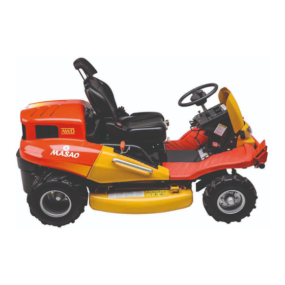
Ride-on Brushcutter
CMX 227/ CM226/ CMX186/ CM185
Operator's Manual
Read this manual completely before operating or maintaining this machine.
Failure to follow safety precautions could result in serious injury or death.
Keep this manual for future reference by you and by all those who operate
and maintain this machine.
Original Instructions
(in English)
5321 5311 003
5335 5311 003
Advertisement
Table of Contents


Need help?
Do you have a question about the CMX 227 and is the answer not in the manual?
Questions and answers
Where is the battery located on a canycom cmx227 lawnmower
The battery on a CanyCom CMX 227 lawnmower is located behind the front cover, tray, and headlight unit.
This answer is automatically generated