Table of Contents
Advertisement
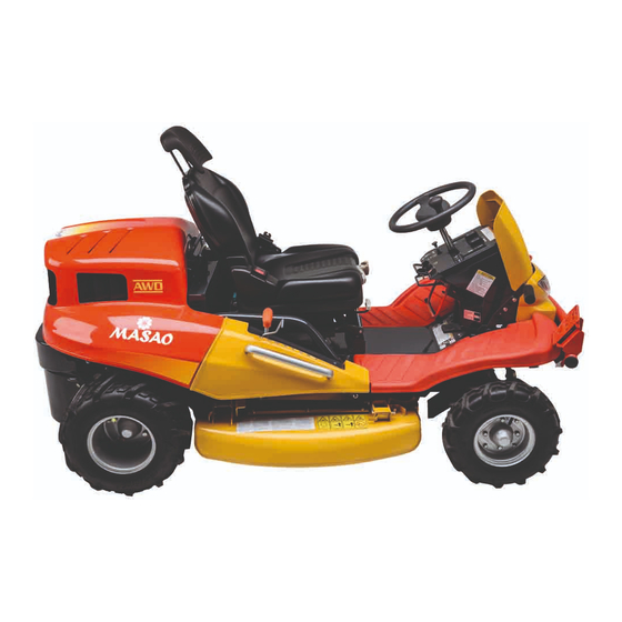
Ride-on Brushcutter
CMX 227/ CM226/ CMX186/ CM185
Operator's Manual
Read this manual completely before operating or maintaining this machine.
Failure to follow safety precautions could result in serious injury or death.
Keep this manual for future reference by you and by all those who operate
and maintain this machine.
Original Instructions
(in English)
5321 5311 003
5347 5351 000
Advertisement
Table of Contents


Need help?
Do you have a question about the CMX 227 and is the answer not in the manual?
Questions and answers
Hi to everyone! My name is Stamatis and I'm emploee of Egaleo Municipality in Attica Greece. We have been suplied with masao cmx227h brushcutter some years ago and now needs to be repaired because the transmition system does not operate at all. Because it is a really remarkable machine we wish to repair but we can't find any specialized mechanic in Greece. Can you help us please? Thanks alot.