Table of Contents
Advertisement
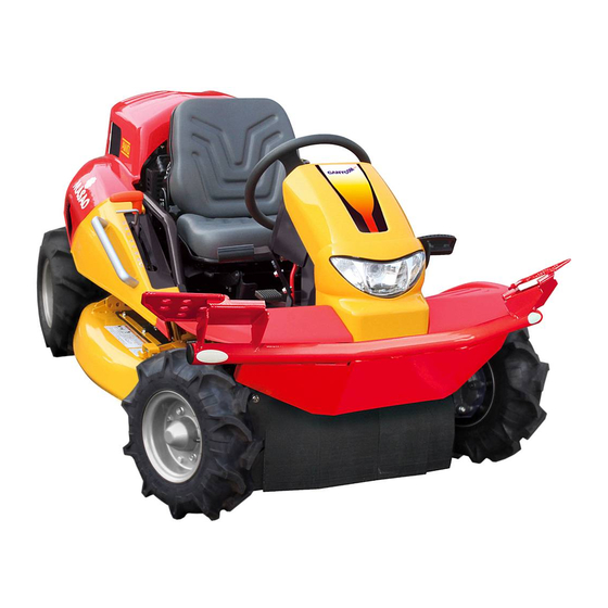
Ride-on Brushcutter
CMX227 / CM226
Operator's Manual
Read this manual completely before operating or maintaining this machine.
Failure to follow safety precautions could result in serious injury or death.
Keep this manual for future reference by you and by all those who operate
and maintain this machine.
Original Instructions
(in English)
5347 5451 001
Advertisement
Table of Contents

Subscribe to Our Youtube Channel
Related Manuals for CanyCom MASAO CMX227


Summary of Contents for CanyCom MASAO CMX227
- Page 1 Ride-on Brushcutter CMX227 / CM226 Operator's Manual Read this manual completely before operating or maintaining this machine. Failure to follow safety precautions could result in serious injury or death. Keep this manual for future reference by you and by all those who operate and maintain this machine.
- Page 2 Notice to Users and Maintenance Personnel Thank you for purchasing this machine. This manual provides information needed for safe and effective use of this machine to those who operate or maintain this machine. Make sure to read and understand the manual thoroughly before operating this machine.
- Page 3 Notice to Owner • Be sure that everyone who uses this machine, including those who rent or lease this machine, receives a copy of this Operator's Manual and understands the importance of reading and following the information in this manual. Warning Terms Used in this Manual In this manual, the following four warning terms are used to signal the four levels of hazard (or seriousness of possible accidents).
- Page 4 Warranty and After-Sales Service Warranty CHIKUSUI CANYCOM, INC. guarantees this product, based on the terms of warranty. After-Sales Service Consult your local CANYCOM dealer or our company’s sales department regarding service orders or any questions or problems that may arise when using this machine. Please make sure to have the product name, serial number, and the make and type of the engine handy at the time of contact.
-
Page 5: Table Of Contents
Contents 1. Safety Safety Labels ........1 Safety Mechanisms . - Page 6 Driving ........27 Starting .
- Page 7 Engine ........59 Engine Oil .
- Page 8 7. Transporting Hauling ........92 Loading and Unloading .
-
Page 9: Safety
• Replace these labels immediately if they have been removed, have fallen off or become illegible. Use the part number, on the label or shown in this manual, to order a replacement label from your CANYCOM representative. AWD Models (CMX227) - Page 10 Safety 5332 5121 000 5347 5109 000 5332 5122 000 5347 5114 000 5305 5326 000 5321 5116 000 5332 5128 000 5332 5127 000 X73-20057-60(Robin Engine) 7DS-24162-00(Yamaha Engine) 5347 5125 000 3667 5063 000 5347M-0101-023E...
-
Page 11: Safety Mechanisms
Safety Safety Mechanisms This product is equipped with the following safety mechanisms. Start Interlock Mechanism The engine can be started only when the parking brake is in [ ] (engaged) position and the mower clutch in [OFF] position. This is to prevent unintended movement of the machine or the cutting blade when starting the engine. -
Page 12: Safety Precautions
Safety Safety Precautions This section contains safety precautions to follow when operating and maintaining the machine. Read and understand the precautions in this section as well as throughout this manual and follow them when operating or maintaining the machine. Failure to follow the safety precautions could result in property damage, serious injury or death to the operator or bystanders. -
Page 13: Preparation
Safety Preparation • Fuel is highly flammable. See Checking and Filling Fuel, page 17 for important safety information on handling fuel. • Always wear the protective footwear, long trousers, hardhat, safety glasses and ear protection when operating or servicing the machine. Proper clothing will minimize the chance of injury. -
Page 14: Operation
Safety Operation This machine is intended for cutting grass and bushes. Any other use may pose hazard or cause damage to the machine. The stability of the machine is affected by the speed, rate of steering, terrain and the operator's weight. Always pay close attention to these factors or a loss of control or tip over could occur, resulting in property damage, serious injury or death. - Page 15 Safety • Always travel slowly and use extra caution when operating on an unfamiliar terrain. Be alert when traveling on a changing terrain. • Never operate on a terrain that you are not comfortable with. Avoid the terrain that is so rough, slippery or loose that you feel like you could tip over.
- Page 16 Safety Driving on a Slope • Never use on the slope steeper than 25 degrees for the CMX2502, CMX227H and CMX186H, and 15 degrees for the CM226H and CM185H. • Driving on the slope can be dangerous. It can result in a tip over and cause serious injury or death.
- Page 17 Safety Cutting When conducting cutting operation, take the following precautions. • Always follow the proper procedures for cutting as described in this manual. • Shut off the work site. Post signs to inform of the cutting operation. Close off the site with rope if necessary to keep people, especially children, off the work site.
-
Page 18: Servicing
Safety Servicing • Do not service the machine when the engine is running. If it is absolutely necessary to run the engine while servicing, pay attention to the moving parts. • Do not operate the engine in a confined space where dangerous carbon monoxide fumes can accumulate. -
Page 19: Controls And Components
Controls and Components Name and Function of Controls Front Cover Seat Fuel Filler Cap Tool Box (Under Front Cover) Handrail Head Light Side Cover, Left Cutting Blade Shield, Left Front Bumper Forward Front Tire Steering Wheel Engine Hood Rear Light (AWD Models Only) Rear Bumper Cutting Blade... - Page 20 Controls and Components 5347M-5351-0201-021 -12-...
- Page 21 Controls and Components 1 Main Switch ... . . Main switch is used to start or stop the engine. 2 Choke Knob ... . . Choke Knob is used to help start the engine by closing the choke valve.
- Page 22 Controls and Components 11 Cutting Height Adjust ..Cutting height adjust lever is used to adjust the cutting height. Grab and hold the cutting height adjust lock and Lever move the cutting height adjust lever back or forth to adjust 12 Cutting Height Adjust the cutting height.
-
Page 23: Specifications
Specifications Product Specifications · Use this product properly after understanding its specifications thoroughly. CMX227 CM226 Model and Type standard standard comfort seat standard & model model model H tire model Machine Mass Mowing Rate 7300 1998 Overall Length Overall Width 1085 1180 Overall Height... -
Page 24: Contents Of Tool Bag
Specifications CMX227 CM226 Model and Type standard comfort standard & standard seat model H tire model High 0 to 13.8 Speed 0 to 7.7 Minimum Turning Radius Gradeability Degrees Stability Degrees (in accordance with the standard measuring method) Main Transmission HST (Continuously Variable) Auxiliary Transmission Constant Mesh... -
Page 25: Operation
Operation Preparation Pre-start up Inspection • Always perform an inspection before every use. If a problem is found, solve or repair it before use. • Clean mowing dust and cut grass before use to avoid fire. • Make sure the cooling air intake is not blocked or clogged. If it is blocked, the engine overheats, resulting in damages to the machine or causing fire. - Page 26 Operation Open the fuel filler cap and fill fuel. Put the fuel filler cap back in place and close Fuel Filler Cap it securely. NOTE • Fuel : Automotive Unleaded Gasoline • Fuel Tank Capacity : 20L 5347M-0401-020E -18-...
-
Page 27: Adjusting Steering Wheel (Yamaha Engine)
Operation Adjusting Steering Wheel • After adjusting steering wheel, try moving steering wheel back and forth and up and down to make sure it is securely locked in its position. Adjusting Angle (Tilting) Steering Wheel Pull up tilt lever to adjust steering wheel angle. -
Page 28: Adjusting Seating Position - (Normal Or Extra Seat)
Operation Adjusting Seating Position (Normal or Extra) • Beware of the pinch points when adjusting the seating position. • After adjusting the seat, try moving the seat back and forth and up and down to make sure it is securely locked in its position. •... - Page 29 Operation Adjusting Stiffness Seat Suspension Adjustment Lever Move the seat suspension adjustment lever to adjust to a desired seat stiffness. 5347M-0401-130E Adjusting Reclining Angle Rotate the reclining knob on the right of the seat to adjust the reclining angle of the seat. NOTE •...
- Page 30 Operation Adjusting Seat Height (Front Part) The height of the seat at the front can be set in one of two positions. NOTE • The height of the seat at the front is set at the high position when shipped from the factory.
- Page 31 Operation Remove the 2 bolts to remove the seat hinge Front Hole bracket. Turn around the seat hinge bracket and mount it to floor with the bolts through the Bolt front holes. Hold the seat in place and install the shaft and hold it with the snap pin, in the reverse Seat hinge Bracket order of 2.
-
Page 32: Adjusting Seating Position - Comfort Seat
Operation Adjusting Seating Position - Comfort Seat • Beware of the pinch points when adjusting the seating position. • After adjusting the seat, try moving the seat back and forth and up and down to make sure it is securely locked in its position. •... - Page 33 Operation Adjusting Stiffness 1. Open the seat suspension adjustment lever Soft handle(1). Hard 2. Turn the seat suspension adjustment lever (2) to adjust the seat suspension stiffness. Seat Suspension Adjustment Lever 5347M-0401-062E Adjusting Reclining Angle Pull up the reclining lever on the left side of the seat to adjust the reclining angle of the Reclining Lever seat.
-
Page 34: Adjusting Drive Pedal
Operation Adjusting Drive Pedal • Always check if the drive pedal is fixed firmly after adjusting. Remove the two bolts fixing the front pedal Front Pedal Drive Pedal Arm with drive pedal arm. Adjust the front pedal into a desired position and fix it with the bolts. -
Page 35: Driving
Operation Driving Starting • Always start and run the engine in a well ventilated place. • Always stay on the seat when starting the engine. Never attempt to start the engine away from the machine. Run over accident may result. •... - Page 36 Using this machine under such conditions may result in an accident or cause damage to machine. If you need to use this machine above that altitude, contact your CANYCOM representative. Make certain the parking brake pedal is Parking Brake Pedal depressed and locked.
- Page 37 Operation Make certain the drive lever is in the neutral Drive Lever position. Neutral Position NOTE • The drive lever returns to the neutral position when the parking brake pedal is fully depressed. 5347M-0402-040E Open the engine hood (see page 56). Open the fuel cock.
-
Page 38: Driving
Operation Turn the main switch to [ ] (ON) position and make sure the oil pressure warning light turns on. Turn the main switch to [ ] (start) position to start the engine. Releas e the key immediately after the engine Oil Pressure starts. - Page 39 Operation • Always make certain of the safety of your surroundings before driving; start slow. Always make certain of the safety of your surroundings before turning. Do not make sudden starts, acceleration, change of speed, change of direction, or stop. Do not turn at speed. Avoid sudden maneuvers; this may cause the operator to fall or to be thrown, or the machine to tip over.
- Page 40 Operation Depress the parking brake pedal to release Parking Brake Pedal the parking brake lock lever. 5347M-0402-121E Driving with Drive Pedal Depress gradually the forward or reverse Drive Pedal side of the drive pedal to move in the corresponding direction. NOTE •...
-
Page 41: Stopping
Operation Stopping • Do not make a sudden stop. Operator may be thrown off, or the machine may skid or tip over. • Always park on a firm, level place. Never park on a potentially dangerous place. • Do not park near combustibles. •... -
Page 42: Shifting
Operation Depress the parking brake pedal to stop the Parking Brake Pedal machine completely. NOTE • When the parking brake pedal is depressed, the drive lever returns to the neutral position. 5347M-0402-121E Shifting • Always shift gears firmly. When the transmission is not firmly shifted, it may jump out of the gear, resulting in loss of control of the machine. -
Page 43: Shifting Between 2Wd And Awd (Awd Models)
Operation Shifting Between 2WD and AWD (AWD models) • Always stop the machine to shift between 2WD or AWD (all-wheel-drive) modes. Shifting gears while the machine is in motion can damage the transmission. • Use the 2WD mode under the normal condition. •... -
Page 44: Locking Differential
Operation Locking Differential The differential can be locked to minimize slipping on the slippery surface. • Always stop the machine to operate the differential lock lever. Operating the differential lock lever while the machine is in motion can damage the differential. -
Page 45: Parking
Operation Parking • Always park on a firm, level place. Never park on a potentially dangerous place. • Avoid parking on a slope. Never park on a slope with an incline of 10 degrees or steeper. If it is absolutely necessary to park the machine on a slope less than 10 degrees, make certain to apply parking brake firmly and block the wheels with chocks. - Page 46 Operation Move the auxiliary transmission shift lever to [N] (neutral) position. Auxiliary Transmission Shift Lever 5347M-0402-101E Turn the main switch to [ ] (off) to stop the engine. Remove the ignition key. Main Switch 5332M-0402-210E Open the engine hood and close the fuel cock.
-
Page 47: Working
Operation Working Inspecting Cutting Blade Inspect the cutting blades before work. Refer to Cutting Blades (page 71) for the inspection procedure. Adjusting Cutting Height Grab the cutting height lock to unlock the Cutting Height Adjust Lever cutting height adjust lever. Cutting Height Lock 5347M-0403-010E With the cutting height lock pulled up, move... -
Page 48: Cutting
Operation Cutting • Never place any part of the body under the cutting blade shield. • Always wear the protective footwear, long trousers, hardhat, safety glasses and ear protection when operating or servicing the machine. Proper clothing will minimize the chance of injury. Do not operate the equipment if you have long hair, loose clothing, or jewelry;... - Page 49 Operation • Always stay on the machine when cuting. • Make sure the air intake for cooling is not clogged or blocked. If it is clogged or blocked, it causes overheating, resulting in damages to the machine. • When working in a dusty area, clean the air filter element twice a day. The dirty air filter element results in poor starting, poor performance, or short service life.
- Page 50 Operation Make sure the cutting blade shield is closed. Cutting Blade Shield 5332M-0403-060E Turn the throttle lever to [ ] (fast) position to raise the engine speed. Throttle Lever 5347M-0402-110E Move the auxiliary transmission shift lever to [L] (low speed). Auxiliary Transmission Shift Lever...
- Page 51 Operation Move the cutting height adjust lever to a Cutting Height Adjust Lever desired height. 5347M-0403-020E Move the mower clutch lever to [ON] to start Mower Clutch Lever mower. NOTE • S a f e t y f e a t u r e : t h e e n g i n e s t o p s automatically if the operator leaves the seat while the mower is running.
- Page 52 Operation Move the mower clutch lever to [OFF] to stop Mower Clutch Lever the mower. NOTE • Moving the mower clutch lever to [OFF] applies the mower brake on the mower to stop. 5347M-0402-021E Move the cutting height adjust lever to the highest position.
-
Page 53: Maintenance
Every 500 hours (clean more frequently in dusty place) Clean carburetor Every 500 hours (clean more frequently in dusty place) Perform valve lapping Every 500 hours (clean more frequently in dusty place) Replace fuel hose Every two years Overhaul 1000 hours (contact Canycom representative for overhaul) -45-... -
Page 54: Chassis
• Perform a pre-startup inspection (PSI) before each use, a monthly inspection once a month, and a yearly inspection once a year. • Some maintenance procedures described below may require special knowledge or tools and instruments. Contact your CANYCOM representative to perform such procedures. Schedule Item... - Page 55 Maintenance Schedule Item Description Note Belt tension shall be properly adjusted. √ √ V-belt Belt shall be free of damage or excessive √ √ wear. √ √ √ Brake shall work properly. Page 70 Parking brake shall be able to hold the Parking Brake √...
- Page 56 Maintenance Schedule Item Description Note Charging Charging system shall charge battery. √ System Battery fluid (electrolyte) shall be at the Page 78 √ √ proper level. Battery Terminals shall be free of looseness or √ √ excessive corrosion. Head and rear lights shall work. √...
-
Page 57: List Of Fluids And Lubricants
Maintenance List of Fluids and Lubricants Item Schedule Grade Cap. Fuel As needed. Automotive Unleaded Gasoline 20 L Engine Oil Fill Gasoline Engine Oil Inspect daily. Fill as needed. API rating: SE or better. 1.4L Change SAE rating: 10W-30 ※(1.55L) Initially - After 20 hours of use. -
Page 58: Greasing Points
Maintenance Greasing Points • Grease regularly. Insufficient greasing may result in seizure or rusting, affecting smooth operation of the machine. NOTE • When using a manual grease pump, push handle five to six times. When handle becomes heavy, stop pushing. •... -
Page 59: Greasing Points (Cm226)
Maintenance Greasing Points (CM 226) Location Schedule Grade Mower deck link pivots Every 6 Months Chassis Grease Mower drive shaft Every 6 Months Chassis Grease Front axle center pivot Every 6 Months Chassis Grease Front knuckles Every 6 Months Chassis Grease Side shield Every 6 Months Chassis Grease... -
Page 60: List Of Consumables And Spares
Maintenance List of Consumables and Spares • When replacing a consumable or spare, always use the CANYCOM genuine part. Using a non-CANYCOM part may reduce the machine's performance or its service life. Note that it may also void the warranty and certification for the relevant standards. - Page 61 Maintenance Item Part No. Schedule Qty. Drive Train Valve*1 *2 53472304000 Replace if defective. Replace if defective (Replace in Brake Lining (Rear) 73019901000 pairs). Replace if defective (Replace in Brake Lining (Front) 73069901000 pairs). Wire (Rear Brake) 53323305500 Replace if defective. Wire (Front Brake) 53323306500 Replace if defective.
-
Page 62: Removing And Installing Body Panels
Maintenance Removing and Installing Body Panels • Cut or pinch hazard exists when removing or installing the body panels; beware of the sharp edges and pinch points. • Make certain to reinstall the panels after removing for repairs or inspection. Front Cover Remove the knob bolts (2 places). -
Page 63: Head Light
Maintenance Head Light Remove the front cover. Remove the 2 knob bolts fixing the tray. Tray Knob Bolt Remove the fixing bracket and lift the tray. Fixing Bracket 5332M-0509-030E Remove the 2 flange bolts fixing the head Flange Bolt light unit to remove the head light unit. Head Light Unit 5347M-0509-041E Insert the projections at the bottom of the... -
Page 64: Engine Hood
Maintenance Engine Hood Pull the lever and open the engine hood. Lever Engine Hood 5332M-0505-030E Rear Cover Remove the 4 bolts. Remove the rear cover. Rear Cover 5332M-0505-040E Step Remove the 3 bolts fixing the step. Step Remove the step. Remove the step on the other side in the same way. -
Page 65: Cutting Blade Shield
Maintenance Seat Bracket • Always slide seat to the rear-most position when lifting seat. If seat is not in the rear- most position, slide lever may interfere with step, preventing seat to be lifted to the holding position. Slide seat to the rear-most position. Safety Pin Lift seat and push safety pin toward inside to hold seat. - Page 66 Maintenance Cutting Blade Shield Lifting up shield 1. Remove bolt and U nut. 2. Raise lock lever. Bolt 3. Hold lock lever and raise blade shield . 4. Release lock lever to lock shield in the raised position. Lock Lever U-Nut 5355M-5353-0505-070 Opening shield to the side Lock Plate Undo the nut to remove the lock plate.
-
Page 67: Engine
Maintenance Engine • Always stop the engine and remove the ignition key before servicing. • An engine that has been running is very hot. Allow the engine to cool before servicing, or severe burns may result. • Keep fire and spark away when servicing. Engine Oil •... - Page 68 Maintenance Inspecting Dipstick Park the machine on a level surface. Open the engine hood. Pull out the dipstick and wipe it clean. Insert the dipstick fully and pull it out. 5347M-0506-010E Visually inspect the oil level. Make sure the oil level is between the upper and lower Upper Limit limits.
-
Page 69: Oil Filter Cartridge
Maintenance Oil Filter Cartridge Open the engine hood. Follow the instructions in Engine Manual to Oil Filter Cartridge change the oil filter cartridge. Close the engine hood. 5347M-0506-050E Air Filter • Clean the air filter element daily. The dirty air filter element causes poor starting, reduces engine performance and shortens engine life. -
Page 70: Spark Plugs
Maintenance Spark Plugs • Never pull an ignition cable when removing a spark plug cap. The conductor in the cable may be severed or damaged. • If a spark plug is damaged, replace it with a new one. Open the engine hood. Spark Plug Cap (On both sides) Follow the instructions in Engine Manual to... -
Page 71: Drive Train
Maintenance Drive Train • Stop the engine and remove the ignition key when servicing the drive train. • Allow the machine to cool off before servicing. An engine and its ancillaries are very hot after operation and may pose a burn hazard. •... -
Page 72: Transmission Oil
Maintenance Transmission Oil NOTE • Oil to use and capacity: Page 49. Park the machine on a level ground. Have an appropriate oil drain pan. Drain Plug Remove the transmission oil drain plug to drain oil. Install the drain plug back in place. Check Bolt 5332M-0507-040E Open the engine hood. -
Page 73: Hst (Hydrostatic Transmission) Oil
Maintenance NOTE • The drain plug for the right front knuckle is on the back side of the front axle. Install both the drain plugs back in place. Filler Cap Remove the right front step. Remove the oil filler cap. Fill the specified amount of oil into the filler. - Page 74 Maintenance Inspecting - Models with charge-pump HST Oil Tank Park the machine on a level ground. Open the engine hood. Filler Cap Unscrew and remove the filler cap. 5335M-0507-010E Wipe the dipstick with clean cloth. Reinstall the filler cap and screw it fully. Lower Limit Filler Cap Unscrew and remove the filler cap again.
- Page 75 Maintenance Remove the oil filter cartridge. Have a new oil filter cartridge. Apply a thin coat of oil onto its oil seal and install it. NOTE • The HST system cannot be fully drained due to its design. • Do not operate the drive pedal or drive lever with the HST oil drained. Doing so lets air into the circuit, necessitating to bleed the circuit.
- Page 76 Maintenance Changing - Models without charge-pump Open the engine hood. Drain Plug Remove the rear cover. Have an appropriate oil drain pan. Remove the filler cap. Remove the drain plug to drain HST oil. NOTE 5347M-0507-061E • The HST system cannot be fully drained due to its design.
-
Page 77: Drive Belt
If it is out of this range, adjust with the adjusting nut. Visually inspect the V-belt. Replace the V-belt if it is damaged. For a replacement, contact Spring your CANYCOM representative. Adjusting Nut Close the engine hood. Drive Belt 5347M-0507-081E... -
Page 78: Parking Brake
5347M-0507-071E NOTE • If the brake does not work even the parking brake pedal is locked, the brake shoe is worn out. Please contact your CANYCOM representative for replacement. Front Brake (AWD Models) Lock the parking brake pedal and inspect that the stretch of the spring is between 5mm and 8mm. -
Page 79: Cutting System
• When replacing the blades, inspect the cutting blade stay. If the stay is worn beyond the wear limit, damaged or deformed, replace it immediately. Contact your CANYCOM representative for replacement. • Blades and cutting blade stay can become sharp due to wear. When handling a blade or cutting blade stay, always wear thick gloves and handle carefully. - Page 80 Blade Pin: Up to either of the shoulder. Inspect the cutting blade stay. If the stay is worn excessively, deformed or damaged, contact your CANYCOM representative and 15mm have it replaced with a new one. Close the cutting blade shield.
- Page 81 Maintenance Replacing Mounting Slot Open the cutting blade shield. Noting the direction of the flat faces on the Flat Face blade pin, shift the blade along the mounting slot to remove. Flat Face 5332M-0508-050E Install a new blade pin and a wave washer to Blade Pin the blade and shift blade along the mounting slot, noting the direction of the flat faces.
-
Page 82: Mower Drive Belt
Remove the engine hood, rear cover and rear bumper. Turn the mower clutch lever to [ON]. Inspect the condition of the V-belt to be free of damages or wear. Replace if damaged or worn. Contact your CANYCOM representative for replacement. -74-... -
Page 83: Mower Brake
5347M-0508-011E notches by adjusting the turnbuckle (V-belt tension cannot be set within the specified Lock Nut range), the V-belt needs to be replaced. Contact your CANYCOM representative for replacement. Reinstall the rear cover, engine hood, and rear bumper. Turnbuckle 5347M-0508-020E Mower Brake •... - Page 84 Maintenance • Never attempt to check the performance of the mower brake with the cutting blade shield open. Stones or rocks can be thrown and cause damage to surrounding properties or persons. • Inspect the mower brake whenever the performance of it seems inadequate. •...
-
Page 85: Mower Gearbox Oil
Maintenance Move the mower clutch lever to [OFF]. Visually inspect if the lining is firmly in contact Lock Nut with the lining groove on the pulley. Shake the turnbuckle to see if there is some Turnbuckle play. Lining If the lining is not firmly in contact with the groove, or the turnbuckle is too tight, readjust the turnbuckle. -
Page 86: Electrical System
Maintenance Electrical System • Always stop the engine and remove the ignition key when servicing the electrical system. • Shock hazard. Do not handle the electrical components with wet hands. Battery • Never charge a battery when the fluid level is below the "lower level" line. Charging a battery with insufficient fluid may shorten the battery life or cause an explosion. - Page 87 Maintenance • Shock hazard: Do not touch the terminals. • Always remove the battery from the machine before charging. Failure to do so causes damage to electrical the components and wiring. • Follow the battery charger user's manual when charging. •...
-
Page 88: Fuses
Maintenance Charging Remove front cover. Remove battery from machine. Follow instructions in battery charger user's manual to charge battery. When battery is fully charged, install battery back in place. Install front cover back in place. 5116M-0509-040E Fuses • If a fuse blows, investigate the cause before replacing. •... -
Page 89: Light Bulbs
Maintenance Light Bulbs • When a light bulb is burnt out, replace it with a new bulb. • When replacing, always use a bulb of the correct rating. A wrong bulb may cause malfunction or damage to the electrical system. •... -
Page 90: After Use Care
Maintenance Replace with a new light bulb. Install the lens back in place. Light Bulb 5332M-0509-080E After Use Care Cutting System • Never place any part of the body under the cutting blade shield when mower is running. • Do not allow bystanders to come near the machine when the mower is running. •... - Page 91 Maintenance Park the machine. Set the cutting height to about 50mm. Connect a hose to the hose connection. Run water through the hose. Hose Connection Start the engine. Turn the throttle lever to [ ] (fast) to raise the engine speed. 5335M-0510-010E Move the mower clutch lever to [ON] to run the mower to clean.
-
Page 92: After Normal Use
Maintenance After Normal Use • Fire hazard; clean the machine of cut grass and similar material after use. Cut grass that is accumulated on the machine can catch fire. • Clean the cooling air intake in front of the engine. If the cooling air intake is clogged or blocked, it causes overheating, resulting in damages to the machine. -
Page 93: After Cold Weather Use
Maintenance After Cold Weather Use • Fire hazard; clean the machine of cut grass and similar material after use. Cut grass that is accumulated on the machine can catch fire. • Do not wash the engine or control panel with running water; water may enter inside and cause rust or damage. -
Page 94: Storage
Maintenance Storage • Fire hazard; do not store the machine where there is a possibility of ignition. • Do not wash the engine or control panel with running water; water may enter inside and cause rust or damage. • Clean the machine before storage; dirt or foreign objects may freeze and cause damage. -
Page 95: Troubleshooting
Troubleshooting chart below. If the malfunction or abnormal condition is not listed in the chart, or the suggested measure does not solve the problem, consult with your CANYCOM representative. • Some corrective measures listed below require special knowledge and/or equipment. - Page 96 Ref. Out of fuel →Fill fuel. Page 17 Other (other than the →Please contact Engine stops abruptly. above). your CANYCOM representative. Insufficient intake air →Clean or replace air Page 61 (clogged air filter). filter element. Idling is not stable. Other (other than the →Please contact...
- Page 97 Engine Wrong engine oil. →Change oil. Page 60 comes out of exhaust Other (other than the →Please contact above). your CANYCOM representative. Insufficient or →Add or change oil. Page 65 deteriorated HST oil. Parking brake is applied →Release parking Machine does not move brake.
- Page 98 Brake times to dry. pulls to one side when Other (other than the →Please contact braked. above). your CANYCOM representative. Improperly inflated tires. →Adjust tire pressure. Page 63 Machine vibrates Other (other than the →Please contact Chassis abnormally.
- Page 99 Troubleshooting Area Malfunction Possible Cause Corrective Measure Ref. Grass is too long. →Cut in several steps at different heights. Engine speed is too low. →Raise engine speed. Driving speed is too high. →Drive slow. Some grass is left uncut. Cutting blade is damaged →Replace.
- Page 100 Transporting Hauling Loading and Unloading • Park the transporter (truck, trailer) on a level ground. Always apply parking brake and use chocks to secure the wheels. • Do not allow bystanders to come close to the machine or the transporter when loading or unloading the machine.
- Page 101 Transporting Set cutting height adjust lever to [150] for CMX227, CM226. Shift auxiliary transmission shift lever to [L] (low speed) and drive machine slowly forward onto the bed. Pay attention not to hit the loading lamp or the bed when loading on a transporter. Park machine according to the instructions in "Parking"...
- Page 102 NOISE LEVEL Model Engine Type Type Speed rpm CMX227 / CM226 Yamaha EH65 3300 rpm 100 dB (A) VIBRATION Vibration Engine Model Rated revolution Hand-arm Whole body 2.8 m/s 0.5 m/s CMX227 / CM226 3300 rpm (uncertainty K=0.70 m/s (uncertainty K=0.16 m/s Values determined according to ISO 5395...
- Page 103 90-1 Fukumasu, Yoshii-machi, Ukiha-shi, Fukuoka, Japan 839-1396 Sales Headquarters TEL +81-(0)943-75-2195 FAX +81-(0)943-75-4396 Authorized Dealer All rights reserved. Unauthorized use or reproduction of this material is prohibited.
Need help?
Do you have a question about the MASAO CMX227 and is the answer not in the manual?
Questions and answers