Advertisement
Advertisement
Table of Contents

Subscribe to Our Youtube Channel
Related Manuals for Exerpeutic 1115


Summary of Contents for Exerpeutic 1115
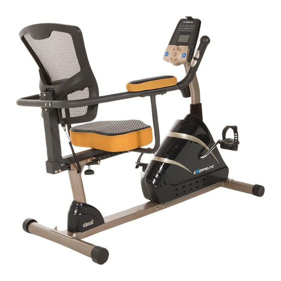
- Page 1 ‘‘Mobile App Tracking’’ Programmable Recumbent Bike IMPORTANT: Read all instructions carefully before using this product. Retain this owner’s manual for future reference. The specifications of this product may vary from this photo, subject to change without notice. OWNER’S MANUAL Item #1115...
-
Page 2: Table Of Contents
TABLE OF CONTENTS SERVICE ------------------------------------------------------------------------ 2 LABEL PLACEMENT --------------------------------------------------------- 3 PRODUCT SAFETY ---------------------------------------------------------- 4 OVERVIEW DRAWING ------------------------------------------------------ 5 PARTS LIST --------------------------------------------------------------------- 6 HARDWARE LIST & TOOLS ----------------------------------------------- 8 ASSEMBLY ---------------------------------------------------------------------- 9 COMPUTER --------------------------------------------------------------------- 20 ADJUSTMENTS ---------------------------------------------------------------- 28 TROUBLE SHOOTING & MAINTENANCE ----------------------------- 29 WARM UP ---------------------------------------------------------------------- 30 WARRANTY -------------------------------------------------------------------- 31 FAX FORM ---------------------------------------------------------------------- 32... -
Page 3: Service
SERVICE IMPORTANT: FOR NORTH AMERICA ONLY To request product service and order replacement parts, please call our customer service department at: 1-866-924-1688 Monday through Friday, 8:00 AM-5:00 PM Pacific Standard Time, service@paradigmhw.com or email us at: Please visit our website at www.paradigmhw.com. Please have the following information ready when requesting for service: Your name Phone number... -
Page 4: Label Placement
LABEL PLACEMENT... -
Page 5: Product Safety
PRODUCT SAFETY Basic precautions should always be followed, including the following safety instructions when using this equipment. Read all instructions before using this equipment. Read all the instructions in this manual and do warm up exercises before using this equipment. Before exercise, in order to avoid injuring the muscle, warm-up exercise of every position of the body is necessary. -
Page 6: Overview Drawing
OVERVIEW DRAWING... -
Page 7: Parts List
PARTS LIST Description Qty No. Description 001 Handrail End Cap Ø32x1.5 2 025 Bushing 002 Bolt M6x70 4 026 Rear Main Frame 003 Washer Ø6xØ12x1.0 5 027 Side Triangle Knob M12 004 Left Handrail Ø32x1.5x1085 1 028 Bottom Triangle Knob M12 Extension Hand Pulse Sensor 005 Backrest 465x465x135 1 029... - Page 8 PARTS LIST Description Qty No. Description 049 Bolt M8x10 4 074 Power Supply Cable L=300 mm Extension Sensor Wire I 1 075 Hexagon Nut 1/2” L=650 mm 051 Extension Sensor Wire L=600 mm 1 076 Adapter L=2000 mm 052 Screw ST2.9x12 2 077 Front Stabilizer End Cap Ø60 053 Sensor with Wire L=300 mm...
-
Page 9: Hardware List & Tools
HARDWARE LIST & TOOLS (#3) Washer (#9) Bolt (#10) Big Curve Washer (#2) Bolt 4 PCS 2 PCS 6 PCS 4 PCS (#11) Cap Nut (#18) Big Washer (#19) Bolt (#22) Bolt 2 PCS 4 PCS 4 PCS 4 PCS (#35) Cap Nut (#36) Big Curve Washer (#37) Bolt... -
Page 10: Assembly
ASSEMBLY Tool: 35 35 35 35 36 36 36 36 Multi Hex Tool with Phillips Screwdriver 78 78 78 78 S10, S13, S14, S15 73 73 73 73 37 37 37 37 Front Stabilizer Installation Lift up the Front Main Frame (73) towards the front, and then align the Front Stabilizer (78) onto the front curve of the Front Main Frame (73). - Page 11 ASSEMBLY Tool: 35 35 35 35 36 36 36 36 26 26 26 26 Multi Hex Tool with Phillips Screwdriver 38 38 38 38 S10, S13, S14, S15 37 37 37 37 Rear Stabilizer Installation Lift up the Rear Main Frame (26) towards the end, and then align the Rear Stabilizer (38) onto the rear curve of the Rear Main Frame (26).
- Page 12 ASSEMBLY Tool: Allen Wrench 6mm 39 39 39 39 26 26 26 26 40 40 40 40 40 40 40 40 29 29 29 29 55 55 55 55 40 40 40 40 39 39 39 39 39 39 39 39 73 73 73 73 Rear Main Frame Installation Use 6mm Allen Wrench to remove six Bolts (39) and six Washers (40) from the Rear Main...
- Page 13 ASSEMBLY Tool: 16 16 23 23 24 24 24 24 Multi Hex Tool with Phillips Screwdriver 21 21 S10, S13, S14, S15 17 17 18 18 19 19 Allen Wrench 5mm Seat and Right/Left Handrail Support Tubes Installation Use the Multi Hex Tool with Phillips Screwdriver to remove four Bolts (24) from the Back and Seat Support Bracket (17).
- Page 14 ASSEMBLY (27) (28) Tool: Allen Wrench 6mm Back/Seat Support Bracket and Seat Sliding Tube Installation Use 6mm Allen Wrench to remove eight Bolts (39) and eight Washers (40) from the Seat Sliding Tube (15). Insert the Seat Sliding Tube (15) into the Bushings (25) of the Rear Main Frame (26). Attach the Back and Seat Support Bracket (17) onto the Seat Sliding Tube (15) with eight Bolts (39) and eight Washers (40) that were removed.
- Page 15 ASSEMBLY Tool: Allen Wrench 6mm Front Post and Front Post Cover and Foot Pedals Installation Use 6mm Allen Wrench to remove four Washers (40), four Bolts (49), one bolt (39), and one Big Curve Washer (36) from the tube of the Front Main Frame (73). Slide the Front Post Cover (54) up to the Front Post (48).
- Page 16 ASSEMBLY Tool: Multi Hex Tool with Phillips Screwdriver S10, S13, S14, S15 Left and Right Foot Pedals Installation The Cranks, Pedal Shafts, and Foot Pedals are marked “R” for Right and “L” for Left. Insert the pedal shaft of Left Foot Pedal (63) into threaded hole in the left Crank (62). Turn the pedal shaft by hand in the counter-clockwise direction until snug.
- Page 17 ASSEMBLY Tool: 12 12 11 11 10 10 13 13 Allen Wrench 5mm 13 13 29 29 17 17 Multi Hex Tool with Phillips Screwdriver S10, S13, S14, S15 ...
- Page 18 ASSEMBLY 20 20 20 20 Tool: 12 12 23 23 21 21 Allen Wrench 5mm 10 10 22 22 Armrests Installation Align and hold the Armrest (20) onto the Right Handrail (12), use 5mm Allen Wrench to tighten two Bolts (22) and two Big Curve Washers (10) until firm and secure. Repeat the same assembly steps to the other Armrest (20) onto the Left Handrail (4).
- Page 19 ASSEMBLY 43 43 50 50 44 44 Tool: 45 45 47 47 46 46 48 48 Multi Hex Tool with Phillips Screwdriver S10, S13, S14, S15 10. Computer and Bottle Holder Installation Use the Multi Hex Tool with Phillips Screwdriver to remove four Bolts (45) from the Computer (43).
- Page 20 ASSEMBLY 71 71 76 76 74 74 11. Adapter Installation Plug one end of the Adapter (76) into the power jack of the Power Supply Cable (74) on the Left Cover (71). Before plugging in, make sure to check carefully the specifications on the Adapter.
-
Page 21: Computer
COMPUTER To quick start, press these buttons in order: 1. RESET -> 2.UPPER ARROW -> 3. START/STOP -> 4. ENTER I. Display: 1. The field is an individual LCD displaying: TIME, RPM\SPEED, DISTANCE, WATT\CALORIES, PULSE, USER. 2. Dot matrix display: ●... - Page 22 COMPUTER III. USER Operation instructions (U0~U4): Select USER 0, USER 1, USER2, USER 3, USER 4: The message reads “U0” until a selection is made. By pressing ▲ or ▼ button to choose from “U0 ~U4”. 1. Press ENTER button to accept “U0~U4”. By pressing the ▲ or ▼ button to adjust the SEX (FEMALE/MALE).
- Page 23 COMPUTER 2. If Press ENTER button to accept PROGRAM By pressing the ▲ or ▼ button to adjust the P1-P12 Press ENTER button to accept program. By pressing the ▲ or ▼ button to adjust the Profile . Press ENTER button to accept LEVEL. By pressing the ▲ or ▼ button to adjust the TIME value.
- Page 24 COMPUTER Press ENTER button to accept TIME. By pressing the ▲ or ▼ button to adjust the DISTANCE value. Press ENTER button to accept DISTANCE. By pressing the ▲ or ▼ button to adjust the CALORIES value. 6. If Press ENTER button to accept H.R.C. (55%, 75%, 90%, Tag) By pressing the ▲...
- Page 25 COMPUTER 2. ENTER button: To confirm set value and enter into the next set value. 3. ▲ and ▼ button: (1). Used to change SEX, AGE, HEIGHT, WEIGHT, TIME, DISTANCE, CALORIES, TARGET HRC and LEVEL; (2). Work level can be changed during a workout. 4.
- Page 26 COMPUTER VII. Pre-defined program profile: ● MANUAL ● PROGRAM ● FITNESS ● PERSONAL ● WATT ● H.R.C. ● RANDOM Program Profile for the P1~P12 Program ● P2 ● P1 ● P3...
- Page 27 COMPUTER ● P5 ● P6 ● P4 ● P8 ● P9 ● P7 ● P11 ● P10 ● P12 Program Profile for the H.R.C. (55%, 75%, 90%, Tag) Program ●HRC (75%) ●HRC (55%) ●HRC (90%) ●HRC (Tag)
- Page 28 Here is the Bluetooth set up example for IPOD. Download APP Application Turn on the IPOD, Go to Apple Store and “Search”. Search for “Exerpeutic pedal monitor”. Click Download. After download successfully, “Pedal Monitor” application will show on the interface.
-
Page 29: Adjustments
ADJUSTMENTS Adjustable Leveler Rear Stabilizer End Cap Adjusting the Rear Stabilizer End Cap or Adjustable Leveler Turn the rear stabilizer end cap on the rear stabilizer or adjustable leveler on the bottom of the rear main frame as needed to level the recumbent bike. Side Triangle Knob Bottom Triangle Knob L Shape Knob... -
Page 30: Trouble Shooting & Maintenance
TROUBLE SHOOTING & MAINTENANCE TROUBLE SHOOTING PROBLEM: The recumbent bike wobbles when in use. SOLUTION: Turn the rear stabilizer end cap on the rear stabilizer or adjustable leveler on the bottom of the rear main frame as needed to level the recumbent bike. PROBLEM: There is no display on the computer console. -
Page 31: Warm Up
WARM UP Quadriceps Stretch With one hand against a wall for balance, reach behind you and pull your right foot up. Bring your heel as close to your buttocks as possible. Hold for 15 counts and repeat with left foot up. Inner Thigh Stretch Sit with the soles of your feet together with your knees pointing outward. -
Page 32: Warranty
WARRANTY Paradigm Health & Wellness, Inc. warrants to the original purchaser that this product is free from defects in material and workmanship when used for the purpose intended, under the conditions that it has been installed and operated in according to Paradigm Health & Wellness, Inc.’s Owner’s Manual. Paradigm Health &... -
Page 33: Fax Form
FAX FORM Paradigm Health & Wellness, Inc. PARTS REQUEST FAX FORM Please fax this form to (1-626-810-2166) OR YOU CAN EMAIL CUSTOMER SERVICE REQUESTS TO service@paradigmhw.com NAME: _______________________________________________________ ADDRESS: ____________________________________________________ CITY ______________ STATE ______________ ZIP ___________________ TELEPHONE: (Day) _____________________________________________ (Night) ____________________________________________ (Email Address) ____________________________________ SERIAL#: __________________________________________ MODEL#: __________________________________________...
Need help?
Do you have a question about the 1115 and is the answer not in the manual?
Questions and answers