Table of Contents
Advertisement
Advertisement
Table of Contents

Subscribe to Our Youtube Channel
Related Manuals for Exerpeutic 1203


Summary of Contents for Exerpeutic 1203
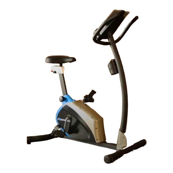
- Page 1 Upright Bike with Pulse IMPORTANT: Read all instructions carefully before using this product. Retain this owner’s manual for future reference. The specifications of this product may vary from this photo, subject to change without notice. OWNER’S MANUAL Item #1203...
-
Page 2: Table Of Contents
TABLE OF CONTENTS SERVICE ------------------------------------------------------------------------ 2 LABEL PLACEMENT --------------------------------------------------------- 3 PRODUCT SAFETY ---------------------------------------------------------- 4 OVERVIEW DRAWING ------------------------------------------------------ 5 PARTS LIST --------------------------------------------------------------------- 6 HARDWARE LIST & TOOLS ----------------------------------------------- 8 ASSEMBLY ---------------------------------------------------------------------- 9 COMPUTER --------------------------------------------------------------------- 18 ADJUSTMENTS ---------------------------------------------------------------- 20 TROUBLE SHOOTING & MAINTENANCE ----------------------------- 21 WARM UP ----------------------------------------------------------------------- 22 WARRANTY -------------------------------------------------------------------- 23 FAX FORM ---------------------------------------------------------------------- 24... -
Page 3: Service
SERVICE IMPORTANT: FOR NORTH AMERICA ONLY To request product service and order replacement parts, please call our customer service department at: 1-866-924-1688 Monday through Friday, 8:00 AM-5:00 PM Pacific Standard Time, service@paradigmhw.com or email us at: Please visit our website at www.paradigmhw.com. Please have the following information ready when requesting for service: Your name Phone number... -
Page 4: Label Placement
LABEL PLACEMENT... -
Page 5: Product Safety
PRODUCT SAFETY Basic precautions should always be followed, including the following safety instructions when using this equipment. Read all instructions before using this equipment. Read all the instructions in this manual and do warm up exercises before using this equipment. Before exercise, in order to avoid injuring the muscle, warm-up exercise of every position of the body is necessary. -
Page 6: Overview Drawing
OVERVIEW DRAWING... -
Page 7: Parts List
PARTS LIST Description Qty No. Description Cross Recessed Pan Head 001 Main Frame 1 025 Tapping Screw ST4.2x25 002 Front Stabilizer Ø60x1.5tx480 1 026 Screw ST4.2x20 003 Rear Stabilizer Ø60x1.5tx650 1 027 Hexagon Nylon Nut M8 (S13) 004 Idler Arm 1 028 Hexagon Nut M6 (S10) 005 Seat Post... - Page 8 PARTS LIST Description Qty No. Description Hand Pulse Sensor with Wire 2 058 Seat Adjustment Knob M10 (L=750 mm) 050 Sensor with Wire (L=1400 mm) 1 059 Washer Ø10xØ20x2t 051 Left Cover 1 060 U Bracket for Seat Sliding Tube Seat Sliding Tube End Cap 052 Right Cover 1 061...
-
Page 9: Hardware List & Tools
HARDWARE LIST & TOOLS (#14) Big Curve Washer (#17) Carriage Bolt (#30) Cap Nut 4 PCS 4 PCS 4 PCS Allen Wrench 6mm Multi Hex Tool with Phillips Screwdriver 1 PC S10, S13, S14, S15 1 PC... -
Page 10: Assembly
ASSEMBLY Tool: Multi Hex Tool with Phillips Screwdriver S10, S13, S14, S15 Front Stabilizer Installation Lift up the Main Frame (1) towards the front, and then align the Front Stabilizer (2) onto the front curve of the Main Frame (1). Attach two Carriage Bolts (17) and on the other ends of bolts with two Big Curve Washers (14) and two Cap Nuts (30). - Page 11 ASSEMBLY Tool: Multi Hex Tool with Phillips Screwdriver S10, S13, S14, S15 Rear Stabilizer Installation Lift up the Main Frame (1) towards the end, and then align the Rear Stabilizer (3) onto the rear curve of the Main Frame (1). Attach two Carriage Bolts (17) and on the other ends of bolts with two Big Curve Washers (14) and two Cap Nuts (30).
- Page 12 ASSEMBLY Tool: Multi Hex Tool with Phillips Screwdriver S10, S13, S14, S15 Left and Right Foot Pedals Installation The Cranks, Pedal Shafts, and Foot Pedals are marked “R” for Right and “L” for Left. Insert the pedal shaft of Left Foot Pedal (44) into threaded hole in the left Crank (39). Turn the pedal shaft by hand in the counter-clockwise direction until snug.
- Page 13 ASSEMBLY Tool: Multi Hex Tool with Phillips Screwdriver S10, S13, S14, S15 Seat Cushion, Seat Sliding Tube, Seat Post, and Seat Post Cover Installation Use the Multi Hex Tool with Phillips Screwdriver to remove three Hexagon Nylon Nuts (27) and three Washers (10) from underside of the Seat Cushion (63). Guide bolts on underside of the Seat Cushion (63) through holes on top of the Seat Sliding Tube (62), attach with three removed Hexagon Nylon Nuts (27) and Washers (10).
- Page 14 ASSEMBLY 19 14 14 19 Tool: 19 14 Allen Wrench 6mm Handlebar Post Installation Use 6mm Allen Wrench to remove six Hexagon Socket Pan Head Cap Bolts (19) and six Big Curve Washers (14) from the Main Frame (1). Insert the Tension Cable (55) through into the bottom end of Handlebar Post (7) and pull it out from the top end of Handlebar Post (7).
- Page 15 ASSEMBLY Tool: Allen Wrench 6mm Handlebar Installation Use 6mm Allen Wrench to remove two Hexagon Socket Pan Head Cap Bolts (19) and two Curve Washers (54) from the Handlebar Post (7). Insert the Hand Pulse Sensor Wires (49) through into a hole on the Handlebar Post (7) and pull it out from the top end of Handlebar Post (7).
- Page 16 ASSEMBLY 18 49 Tool: Multi Hex Tool with Phillips Screwdriver S10, S13, S14, S15 Computer Installation Use the Multi Hex Tool with Phillips Screwdriver to remove four Cross Recessed Pan Head Bolts (42) from the Computer (15). Put the cable end of resistance cable of Tension Control Knob (15) into the cable lock of Tension Cable (55), see Figure A.
- Page 17 18 49 ASSEMBLY Tool: Multi Hex Tool with Phillips Screwdriver S10, S13, S14, S15 Left and Right Decorate Covers Installation Use the Multi Hex Tool with Phillips Screwdriver to remove one Cross Recessed Pan Head Tapping Screw (25) from the Left and Right Decorate Covers (40, 41). Use the Multi Hex Tool with Phillips Screwdriver to remove two Screws (26) from the Main Frame (1).
- Page 18 ASSEMBLY Tool: Multi Hex Tool with Phillips Screwdriver S10, S13, S14, S15 Seat Sliding Tube Cover Installation Use the Multi Hex Tool with Phillips Screwdriver to remove three Cross Recessed Pan Head Bolts (65) from the Seat Post (5). Slide the Seat Sliding Tube Cover (64) onto the top end of the Seat Post (5) with three Cross Recessed Pan Head Bolts (65) that were removed.
-
Page 19: Computer
COMPUTER BUTTON USING YOUR COMPUTER The computer can be activated by pressing the button or by pedaling. If you leave the equipment idle for approximate 5 minutes, the power will turn off automatically. BUTTON FUNCTIONS: Press the button to select each function of computer. Press and hold the button for 3 seconds, all data values will clear to zero except the ODO (ODOMETER) data values. - Page 20 COMPUTER CAL (CALORIES): Displays the total accumulated calories burned during workout. (This data is a rough guide for comparison of different exercise sessions and should not be used in medical treatment). ODO (ODOMETER): Displays the total accumulative distance traveled. RPM (Revolutions per Minute): Displays the current revolutions per minute. PULSE : Displays your current heart rate figures after you grip the handlebar sensors with both your hands during exercise.
-
Page 21: Adjustments
ADJUSTMENTS Adjusting the Tension Control Knob To increase the tension, turn the tension control knob in a clockwise direction. To decrease the tension, turn the tension control knob in a counterclockwise direction. Tension Control Knob Adjusting the Rear Stabilizer End Cap Turn the rear stabilizer end cap on the rear stabilizer as needed to level the upright bike. -
Page 22: Trouble Shooting & Maintenance
TROUBLE SHOOTING & MAINTENANCE TROUBLE SHOOTING PROBLEM: The upright bike wobbles when in use. SOLUTION: Turn the rear stabilizer end cap on the rear stabilizer as needed to level the upright bike. PROBLEM: There is no display on the computer console. SOLUTION: Remove the computer console and verify the wires that come from the computer console are properly connected to the wires that come from the handlebar post. -
Page 23: Warm Up
WARM UP Quadriceps Stretch With one hand against a wall for balance, reach behind you and pull your right foot up. Bring your heel as close to your buttocks as possible. Hold for 15 counts and repeat with left foot up. Inner Thigh Stretch Sit with the soles of your feet together with your knees pointing outward. -
Page 24: Warranty
WARRANTY Paradigm Health & Wellness, Inc. warrants to the original purchaser that this product is free from defects in material and workmanship when used for the purpose intended, under the conditions that it has been installed and operated in according to Paradigm Health & Wellness, Inc.’s Owner’s Manual. Paradigm Health &... -
Page 25: Fax Form
FAX FORM Paradigm Health & Wellness, Inc. PARTS REQUEST FAX FORM Please fax this form to (1-626-810-2166) OR YOU CAN EMAIL CUSTOMER SERVICE REQUESTS TO service@paradigmhw.com NAME: _______________________________________________________ ADDRESS: ____________________________________________________ CITY ______________ STATE ______________ ZIP ___________________ TELEPHONE: (Day) _____________________________________________ (Night) ____________________________________________ (Email Address) ____________________________________ SERIAL#: __________________________________________ MODEL#: __________________________________________...
Need help?
Do you have a question about the 1203 and is the answer not in the manual?
Questions and answers