Table of Contents
Advertisement
Prog
P
IMPO
ORTANT: R
this o
owner's m
The s
specificatio
witho
out notice.
1115
5.5‐0623
316
''M
Mob
bile A
ram
mab
Read all in
nstructions
manual for
r future ref
ons of this
product m
OW
WNER
App T
Trac
ble R
ecum
s carefully
y before u
ference.
may vary fro
om this pho
R'S M
MANU
king
g''
mben
nt Bi
using this
product. R
oto, subjec
ct to chang
AL
ike
Retain
ge
Advertisement
Table of Contents

Related Manuals for Exerpeutic 1115


Summary of Contents for Exerpeutic 1115
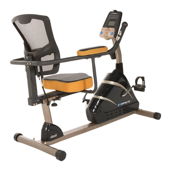
- Page 1 Retain this o owner’s m manual for r future ref ference. The s specificatio ons of this product m may vary fro om this pho oto, subjec ct to chang witho out notice. WNER R’S M MANU AL 1115 5.5‐0623 316 ...
- Page 2 ...
-
Page 3: Table Of Contents
TABLE OF CONTENTS SERVICE ------------------------------------------------------------------------ 2 LABEL PLACEMENT --------------------------------------------------------- 3 PRODUCT SAFETY ---------------------------------------------------------- 4 OVERVIEW DRAWING ------------------------------------------------------ 5 PARTS LIST --------------------------------------------------------------------- 6 HARDWARE & TOOLS PACK ---------------------------------------------- 8 ASSEMBLY ---------------------------------------------------------------------- 9 COMPUTER --------------------------------------------------------------------- 20 ADJUSTMENTS ---------------------------------------------------------------- 28 TROUBLE SHOOTING & MAINTENANCE ----------------------------- 29 WARRANTY -------------------------------------------------------------------- 30 PARTS REQUEST FORM --------------------------------------------------- 31... -
Page 4: Service
SERVICE IMPORTANT: FOR NORTH AMERICA ONLY For damage or defective product, questions, replacement parts or any other service support, please contact our customer service department (8:00 AM - 5:00 PM Pacific Standard Time, Daily) by below methods: For Best Service Email: Service@paradigmhw.com Website: www.paradigmhw.com... -
Page 5: Label Placement
LABEL PLACEMENT 1115 1115 Under Penalty of law this tag not to NOTICE be removed except by the consumer ALL NEW MATERIAL CONSISTING OF This article does not meet POLYURETHANE FOAM PAD_100% REGISTRY NO. ments of California Bureau of VA25302 (CN) Home Furnishings technical bulletin. -
Page 6: Product Safety
PRODUCT SAFETY Basic precautions should always be followed when using this equipment. Read all instructions before using this equipment which include the following safety instructions: Read all the instructions in this manual and do warm up exercises before using this equipment. Before exercising, and in order to avoid injuring your muscles, it is recommended that you perform warm-up exercises for every muscle group. -
Page 7: Overview Drawing
OVERVIEW DRAWING... -
Page 8: Parts List
PARTS LIST Description Qty No. Description 001 Handrail End Cap Ø32x1.5 2 025 Bushing 002 Bolt M6x70 4 026 Rear Main Frame Extension Hand Pulse Sensor 003 Washer Ø6xØ12x1.0 5 029 Wire I L=1300 mm Phillips Self Tapping Screw 004 Left Handrail Ø32x1.5x1085 1 030 ST4.8x20 005 Backrest 465x465x135... - Page 9 PARTS LIST Description Qty No. Description 051 Extension Sensor Wire L=600 mm 1 075 Hexagon Nut 1/2” 052 Screw ST2.9x12 2 076 Adapter L=2000 mm 053 Sensor with Wire L=300 mm 1 077 Front Stabilizer End Cap Ø60 054 Front Post Cover 1 078 Front Stabilizer Ø60x1.5x580 Extension Hand Pulse Sensor...
-
Page 10: Hardware & Tools Pack
HARDWARE & TOOLS PACK ... -
Page 11: Assembly
ASSEMBLY Tool: Multi Hex Tool with Phillips Screwdriver S10, S13, S14, S15 1PC 35 35 35 35 36 36 36 36 78 78 78 78 73 73 73 73 37 37 37 37 Front Stabilizer Installation Lift up the Front Main Frame (73), and align the Front Stabilizer (78) onto the front curve of the Front Main Frame (73). - Page 12 ASSEMBLY Tool: Multi Hex Tool with Phillips Screwdriver S10, S13, S14, S15 1PC Rear Stabilizer Installation Lift up the Rear Main Frame (26), and align the Rear Stabilizer (38) onto the rear curve of the Rear Main Frame (26). Insert two Bolts (37) into the Rear Stabilizer (38), then on the threaded ends of the Bolts (37) attach two Big Curve Washers (36) and two Cap Nuts (35).
- Page 13 ASSEMBLY Tool: 6mm Allen Wrench with Phillips Screwdriver 1 PC Main Frame Assembly Use the 6mm Allen Wrench with Phillips Screwdriver provided to remove the six Bolts (39) and the six Washers (40) from the Rear Main Frame (26). Connect the Extension Hand Pulse Sensor Wire I (29) from the Rear Main Frame (26) with the Extension Hand Pulse Sensor Wire II (55) from the Front Main Frame (73).
- Page 14 ASSEMBLY Tool: 6mm Allen Wrench with Phillips Screwdriver 4.1 Right/Left Handrail Support Tubes Installation Use the Multi Hex Tool with Phillips Screwdriver to remove the four Bolts (24) from the Back and Seat Support Bracket (17). Align the holes of the Right Handrail Support Tube (21) and the Back and Seat Support Bracket (17).
- Page 15 ASSEMBLY Tool: 6mm Allen Wrench with Phillips Screwdriver 5.1 Seat Sliding Tube Installation Use the 6mm Allen Wrench with Phillips Screwdriver to remove the eight Bolts (39) and the eight Washers (40) from the Seat Sliding Tube (15). Insert the Seat Sliding Tube (15) into the Bushing (25) of the Rear Main Frame (26).
- Page 16 ASSEMBLY Tool: 6mm Allen Wrench with Phillips Screwdriver 6. Front Post and Front Post Cover installation Use the 6mm Allen Wrench with Phillips Screwdriver provided to remove the four Washers (40), four Bolts (49), one Bolt (39), and one Big Curve Washer (36) from the tube of the Front Main Frame (73).
- Page 17 ASSEMBLY Tool: Multi Hex Tool with Phillips Screwdriver S10, S13, S14, S15 1PC 7. Left and Right Foot Pedals Installation NOTE: The Cranks, Pedal Shafts, and Foot Pedals are marked “R” for Right and “L” for Left. Insert the Left Foot Pedal (63) into the threaded hole in the left side of the Crank with Belt Pulley (62).
- Page 18 ASSEMBLY Tool: Allen Wrench 5mm Multi Hex Tool with Phillips Screwdriver S10, S13, S14, S15 1PC Left/Right Handrails and Backrest Installation Attach the Backrest (5) and Left Handrail (4) onto the Back and Seat Support Bracket (17), using four Bolts (2) and four Washers (3).
- Page 19 ASSEMBLY Tool: Allen Wrench 5mm 9. Armrests Installation Align the holes of the Armrest (20), the Right Handrail (12), and the Right Hand Support Tube (21). Fasten the three parts together with two Bolts (22) and two Big Curve Washers (10). Use the 5mm Allen Wrench provided to tighten the two Bolts (22) and two Big Curve Washers (10) until firm and secure.
- Page 20 ASSEMBLY Tool: Multi Hex Tool with Phillips Screwdriver S10, S13, S14, S15 1PC 10. Computer and Bottle Holder Installation Use the Multi Hex Tool with Phillips Screwdriver provided to remove the four Bolts (45) from the back of the Computer (43). Connect the Extension Hand Pulse Sensor Wires III (44) and Extension Sensor Wire I (50) to the wires at the rear of the Computer (43).
- Page 21 ASSEMBLY 11. Adapter Installation Plug one end of the Adapter (76) into the power jack of the Power Supply Cable (74) on the Left Cover (71). Before plugging in, make sure to carefully check the specifications on the Adapter (76). Plug the other end of the Adapter (76) into the electrical wall outlet.
-
Page 22: Computer
OMPUTE I. Dis splay: 1. T The LCD d display sho ows the foll owing wor rkout statis stics: TIME, RPM M, SPEED, , DISTANC CE, CALOR RIES, PUL LSE, and U USER 2. P Program P Profiles: Th e LCD disp play will sh how the pro ogram prof... - Page 23 OMPUT utton Fun nctions: III. OP: Press t the START T/STOP bu utton to sta art or stop t the workou ut clock. TART/STO P: Press th he UP butt on to navig gate throug gh the train ning progra am modes (Manual, P Pre-set...
- Page 24 OMPUTE IV. PR ROGRAM OPTION I NSTRUCT TIONS: ANUAL WO ORKOUTS S: Lets yo u set the w workout r resistance e level man nual. Select th he MANUAL L Program f feature and then push the ENTER button. Use the UP and DO OWN button s to set a R...
- Page 25 OMPUT ATT: The te ension will adjust to m maintain a a 50 WATT workout. Select th he WATT fe eature and t hen push th he ENTER b button. Use the UP and DO OWN button s to set a T TIME goal.
- Page 26 OMPUT eart Rate C Control (H H.R.C.): Te nsion will l change t o get user r to the se elected He eart Rate Z Zone. 1. Selec t the H.R.C C feature 2. Selec t a Heart Ra ate Zone, E Either 55%, 75%, 90% or TAG.
- Page 27 COMPUTER VI. Functions View: Below is a list of Functions and their Values and how they display on the console. Item Display Display Rang Stored MALE/ FEM GENDER 10-100 20-330 (Lb) WEIGHT 10-150 (KG) 36-84 (INCH) HEIGHT 90-210 (CM) 0:00-99:59 TIME 0.0-99.99 DISTANCE...
- Page 28 OMPUT VII. P Pre-defin ned prog gram pro file: ● ● MANUAL ● PROGR ● FITNE ● PERSO ONAL ● H.R.C ● WATT ● ● ● RANDOM ogram Pr rofile for r the P1~ ~P12 Pro gram ● P2 ● P3 ●...
- Page 29 OMPUT ● P5 ● P6 ● P4 ● P8 ● P7 ● P9 ● P11 ● P12 ● P10 Progra m Profile e for the H.R.C. ( 55%, 75% %, 90%, Tag) Pro ogram ●HRC (75%) ●HRC (5 55%) ●HRC C (90%) ●HRC (T Tag)
-
Page 30: Adjustments
ADJUSTMENTS Adjustab b le Levele (42) Rear S Stabilizer End Cap (34) Adjusting the Rear Stabilizer End Cap and the Adjustable Leveler: To prevent shaking during a workout adjust the Rear Stabilizer End Caps (34) and the Adjustable Leveler (42) as needed to the level the Bike with the ground. L Sha a pe Knob (97) Adjusting the Seat Forward or Back Turn the L Shape Knob (97) in a counter-clockwise direction until the seat can slide... -
Page 31: Trouble Shooting & Maintenance
TROUBLE SHOOTING & MAINTENANCE TROUBLE SHOOTING PROBLEM: The recumbent bike wobbles when in use. SOLUTION: Turn the Rear Stabilizer End Caps on the Rear Stabilizer or the Adjustable Leveler on the bottom of the Rear Main Frame as needed to level the recumbent bike. See the Adjustments page 25. PROBLEM: There is no display on the computer console. -
Page 32: Warranty
WARRANTY MANUFACTURER’S LIMITED WARRANTY Paradigm Health & Wellness warrants to the original purchaser that this product is free from defects in material and workmanship when used for the purpose intended, under the conditions that it has been installed and operated in accordance with Paradigm’s Owner’s Manual. -
Page 33: Parts Request Form
PARTS REQUEST FORM Paradigm Health & Wellness, Inc. EMAIL THIS FORM WITH YOUR RECIEPT OF PURCHASE TO Service@paradigmhw.com * NAME: _______________________________________________________ ADDRESS: ____________________________________________________ CITY ______________ STATE ______________ ZIP ___________________ TELEPHONE: (Day) ____________________________________________ (Night) ____________________________________________ SERIAL#: _____________________________________________________ MODEL#: _____________________________________________________ PURCHASE DATE: _____________________________________________ PLACE OF PURCHASE: _________________________________________ PART # DESCRIPTION “YOUR ORDER WILL BE PROCESSED WITHIN 3 BUSINESS DAYS”...