Table of Contents

Related Manuals for Exerpeutic 1111


Summary of Contents for Exerpeutic 1111
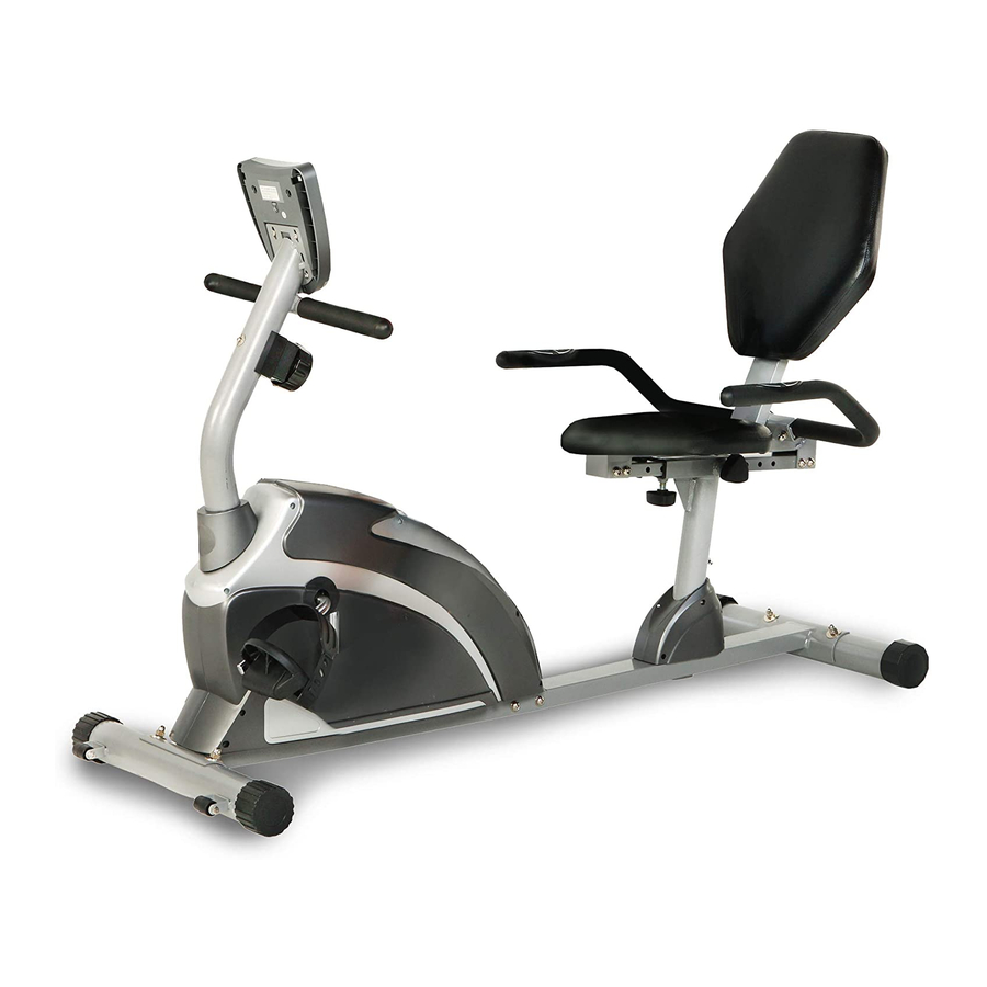
- Page 1 RECUMBENT BIKE IMPORTANT: Read all instructions carefully before using this product. Retain this owner’s manual for future reference. The specifications of this product may vary from this photo, subject to change without notice. OWNER’S MANUAL Item#1111...
- Page 2 1111.3-082615...
-
Page 3: Table Of Contents
TABLE OF CONTENTS SERVICE ------------------------------------------------------------------------ 2 LABEL PLACEMENT --------------------------------------------------------- 3 PRODUCT SAFETY ---------------------------------------------------------- 4 OVERVIEW DRAWING ------------------------------------------------------ 5 PARTS LIST --------------------------------------------------------------------- 6 HARDWARE PACKING LIST & TOOLS --------------------------------- 8 ASSEMBLY --------------------------------------------------------------------- 9 COMPUTER ---------------------------------------------------------------- ADJUSTMENTS ---------------------------------------------------------------- 18 TROUBLE SHOOTING & MAINTENANCE ----------------------------- 19 WARM UP ----------------------------------------------------------------------- 20 WARRANTY -------------------------------------------------------------------- 22 PART REQUEST FORM ----------------------------------------------------- 23... -
Page 4: Service
SERVICE IMPORTANT: FOR NORTH AMERICA ONLY For damaged or defective product, questions, replacement parts or any other service support, please contact our customer service department (8:00 AM - 5:00 PM Pacific Standard Time, Daily) by the below methods: For Best Service, please Email: Service@paradigmhw.com Response Time: 1-2 Business Days Website:... -
Page 5: Product Safety
PRODUCT SAFETY... -
Page 6: Overview Drawing
Basic precautions should always be followed, including the following safety instructions when using this equipment. Read all instructions before using this equipment. 1. Read all the instructions in this manual and do warm up exercises before using this equipment. 2. Before exercise, in order to avoid injuring your muscles, warm-up exercise for every muscle group is highly recommended. -
Page 8: Parts List
PARTS LIST Description Qty No. Description 001 Back and Seat Support Bracket 1 027 Wire Plug Ø12.1 53x23x2.0 002 Front Stabilizer Ø60x1.5x580 1 028 Bolt M8x18 003 Rear Main Frame 1 029 Locknut M6 004 Rear Stabilizer Ø60x1.5x580 1 030 Bolt M8x70 005 Front Main Frame 80x40x2 1 031 Spring 006 Front Handlebar Post Ø50x1.5... -
Page 9: Hardware Packing List & Tools
Description Qty No. Description 053 Nut M10x1 2 067 Pan Head Phillips Self Drilling Screw ST4.2x15 054 Bushing 2 068 Hand Pulse Sensor Wire L=650mm 2 055 Middle Section Hand Pulse 2 069 Pan Head Phillips Self Drilling Sensor Wire Screw ST4.2x25 056 Idle Wheel 1 070 Bolt M8x45... -
Page 10: Assembly
(24) Washer Ø8 (25) Curve Washer Ø8 (30) Bolt M8x70 2 PCS 6 PCS 4 PCS (32) Cap Nut M8 (70) Bolt M8x45 6 PCS 2 PCS TOOLS Allen Wrench S6 Multi Hex Tool with Phillips Screwdriver 1 PC 1 PC ASSEMBLY... - Page 11 Tool: Allen Wrench S6 1. Rear Main Frame Installation Remove two M8x30 Bolts (49), four M8x15 Bolts (23), and six Ø8 Washers (24) from the Rear Main Frame (3). Remove bolts with the Allen Wrench provided. Connect the Middle Section Hand Pulse Sensor Wires (55) from the Rear Main Frame (3) to the Extension Hand Pulse Sensor Wires (65) from the Front Main Frame (5).
- Page 12 Tool: Multi Hex Tool with Phillips Screwdriver 2. Front and Rear Stabilizers Installation Position the Front Stabilizer (2) in front of the Front Main Frame (5) and align bolt holes. Attach the Front Stabilizer (2) onto the front curve of the Front Main Frame (5) with two M8x70 Bolts (30), two Ø8 Curve Washers (25), and two M8 Cap Nuts (32).
- Page 13 ASSEMBLY Tool: Allen Wrench S6 Multi Hex Tool with Phillips Screwdriver 3. Front Handlebar Post and Foot Pedal Installation Remove four M8x15 Bolts (23) and four Ø8 Curve Washers (25) from the Front Main Frame (5). Slide the Front Handlebar Post Cover (74) up to the Front Handlebar Post (6).Insert the Tension Cable (40) through into the bottom hole of Front Handlebar Post (6) and pull it out from the square hole of Front Handlebar Post (6).
- Page 14 ASSEMBLY Tool: Allen Wrench S6 Multi Hex Tool with Phillips Screwdriver 4. Seat Sliding Tube, Back/Seat Support Bracket, and Handlebar Installation Remove eight M8x15 Bolts (23) and eight Ø8 Washers (24) from the Back/Seat Support Bracket (1) and Seat Sliding Tube (15). Remove bolts with the Allen Wrench provided.
- Page 15 ASSEMBLY Hardware: 2 Cap Nuts (M8) 2 Bolts (M8x45) 2 Curve Washers (Ø8) 2 Washers (Ø8) Tool: Multi Hex Tool with Phillips Screwdriver 5. Computer Installation Remove four M5x10 Bolts (39) from the Computer (9). Remove bolts with the Multi Hex Tool with Phillips Screwdriver provided. Connect the Extension Wires (63) and Extension Sensor Wire (64) to the wires that come from the Computer (9).
-
Page 16: Computer
Tool: Multi Hex Tool with Phillips Screwdriver 6. Seat and Back Cushions Installation Remove eight M6x15 Bolts (21) and eight Ø6 Washers (58) from the back of the Seat and Back Cushions (7, 8). Remove bolts with the Multi Hex Tool with Phillips Screwdriver provided. -
Page 17: Operating The Computer
OPERATING THE COMPUTER SPECIFICATIONS: TIME --------------------------------------------------- 0:00-99:59 MIN: SEC SPEED ------------------------------------------------ 0.0-999.9 MPH DIST (DISTANCE) ---------------------------------- 0.0-999.9 MILE CAL (CALORIES) ----------------------------------- 0.0-999.9 KCAL ODO (ODOMETER) -------------------------------- 0.0-999.9 MILE (PULSE) ------------------------------------------ 40-240 BEATS/MIN BUTTON FUNCTIONS: MODE: Press MODE button to select each function of computer. Press and hold MODE button for 3 seconds, all data values will clear to zero except the ODO (ODOMETER) data values. - Page 18 SPEED: Press MODE button until the screen displays SPEED; the computer will display the current training speed. DIST (DISTANCE): Press MODE button until the screen displays DIST; the computer will display the accumulative distance traveled during workout. When you start to exercise, distance starts counting up from 0.0 to 999.9 miles per 0.1 mile increment.
- Page 19 HOW TO INSTALL THE BATTERIES: Remove the battery cover at the rear of computer. Place two "SIZE-AA" batteries into the battery housing. Insure batteries are correctly positioned and battery springs are in proper contact with batteries. Re-install the battery cover. If the display is illegible or only partial legible, remove batteries and wait 15 seconds before reinstalling.
-
Page 20: Adjustments
ADJUSTMENTS Adjusting the Tension Control Knob To increase the load, turn the tension control knob in a clockwise direction. To decrease the load, turn the tension control knob in a counterclockwise direction. Tension Control Knob Adjusting the Rear Stabilizer End Cap Turn the rear stabilizer end cap on the rear stabilizer as needed to level the elliptical trainer Rear Stabilizer End Cap... -
Page 21: Trouble Shooting & Maintenance
TROUBLE SHOOTING & MAINTENANCE Cleaning The recumbent bike can be cleaned with a soft cloth and mild detergent. Do not use abrasives or solvents on plastic parts. Please wipe your perspiration off the recumbent bike after each use. Be careful not get excessive moisture on the computer display panel as this might cause an electrical hazard or electronics to fail. -
Page 22: Warm Up
WARM UP The WARM-UP is an important part of any workout. You should begin every session by stretching your muscles to prepare your body for more strenuous exercise. This will help increasing your circulation and pulse rate, and deliver more oxygen to your muscles HEAD ROLLS Rotate your head to the right for one count, you should feel a stretching sensation up the left side of your neck. - Page 23 WARM UP INNER THIGH STRETCH Sit with the soles of your feet together and your knees pointing outward. Pull your feet as close to your groin as possible. Gently push your knees toward the floor. Hold for 15 counts. TOE TOUCHES Slowly bend forward from your waist, letting your back and shoulders relax as you stretch toward your toes.
-
Page 24: Warranty
WARRANTY MANUFACTURER’S LIMITED WARRANTY Paradigm Health & Wellness warrants to the original purchaser that this product is free from defects in material and workmanship when used for the purpose intended, under the conditions that it has been installed and operated in accordance with Paradigm’s Owner’s Manual. -
Page 25: Part Request Form
PART REQUEST FORM Paradigm Health & Wellness, Inc. EMAIL THIS FORM WITH YOUR RECIEPT OF PURCHASE TO Service@paradigmhw.com NAME: _______________________________________________________ ADDRESS: ____________________________________________________ CITY ______________ STATE ______________ ZIP ___________________ TELEPHONE: (Day) ____________________________________________ (Night) ____________________________________________ SERIAL#: _____________________________________________________ MODEL#: _____________________________________________________ PURCHASE DATE: _____________________________________________ PLACE OF PURCHASE: _________________________________________ PART # DESCRIPTION...
Need help?
Do you have a question about the 1111 and is the answer not in the manual?
Questions and answers
When I peddle the bike it has a lot of resistance and is making a loud noise
Your Exerpeutic bike model 1111 may be making a loud noise because the bolts on the bike may be loose. The high resistance while pedaling could also be related to improper assembly or maintenance. Inspect and tighten all bolts, especially on moving parts, to resolve the noise. Regular maintenance, including checking pedal and assembly bolt tightness weekly, is recommended.
This answer is automatically generated