Table of Contents

Subscribe to Our Youtube Channel
Related Manuals for Exerpeutic EXERWORK 1000


Summary of Contents for Exerpeutic EXERWORK 1000
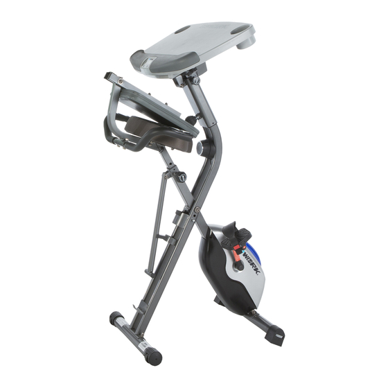
- Page 1 Desk Bike IMPORTANT: Read all instructions carefully before using this product. Retain this owner’s manual for future reference. The specifications of this product may vary from this photo, subject to change without notice. OWNER’S MANUAL 7150.7-020918...
- Page 2 PLEASE DO NOT RETURN THIS PRODUCT TO THE STORE. STOP. Contact customer service if you have any questions regarding assembly or proper operation of the machine. Email us at: Service@paradigmhw.com Or call us at: 1-844-641-7921 Hours: 8:00 am to 5:00 pm (PST) Monday thru Friday...
-
Page 3: Table Of Contents
TABLE OF CONTENTS SERVICE------------------------------------------------------------------------------- LABEL PLACEMENT---------------------------------------------------------------- IMPORTANT SAFETY GUIDELINES------------------------------------------- OVERVIEW DRAWING------------------------------------------------------------- PARTS LIST--------------------------------------------------------------------------- HARDWARE & TOOLS PACK--------------------------------------------------- ASSEMBLY---------------------------------------------------------------------------- CONSOLE ---------------------------------------------------------------------------- OPERATIONS & ADJUSTMENTS---------------------------------------------- BATTERY INSTALLATION-------------------------------------------------------- STORAGE----------------------------------------------------------------------------- TRANSPORTION-------------------------------------------------------------------- MAINTENANCE & TROUBLESHOOTING---------------------------------- WARRANTY--------------------------------------------------------------------------- PART REQUEST FORM-----------------------------------------------------------... -
Page 4: Service
SERVICE IMPORTANT: FOR NORTH AMERICA ONLY For damaged or defective product, questions, replacement parts or any other service support, please contact our customer service department by the below methods: For The Best Service, please Email: service@paradigmhw.com Response Time: 1-2 Business Days Emailing us with the information above will be the best method to receive a response during peak business hours Website:... -
Page 5: Label Placement
LABEL PLACEMENT... -
Page 6: Important Safety Guidelines
IMPORTANT SAFETY GUIDELINES Basic precautions should always be followed, including the following safety guidelines when using this desk bike. Read all of the guidelines before using this desk bike. Before exercising and to avoid injuring your muscles, it is highly recommended that you perform warm-up exercises for each muscle group. - Page 7 IMPORTANT SAFETY GUIDELINES Do not use this equipment if you have any of the following conditions or ailments: Pregnancy Extreme obesity Middle ear infection Hiatus hernia or Ventral hernia Glaucoma, retinal detachment or conjunctivitis Use of anticoagulants including Aspirin in high doses.
-
Page 8: Overview Drawing
OVERVIEW DRAWING... -
Page 9: Parts List
PARTS LIST Description Description Rear Frame Washer Ø6.2 Front Frame Sensor with Wire Rear Stabilizer Flywheel Ø195 Handlebar Belt Wheel with Crank Axle Ø155 Seat Post Bearing Bracket Seat Wave Washer Left Pedal Bearing 6003RS 7-1 Left Pedal Strap C-ring Ø17 Right Pedal Belt Wheel with Crank Axle Ø150 8-1 Right Pedal Strap... - Page 10 No. Description Description 73 Front Stabilizer End Cap Connection Wire B 74 Spring Washer Ø 6.2 100 Drilling Screw M4x10 75 Hexagon Socket Bolt M8x80L 101 Hexagon Socket Bolt M8*45 76 Hexagon Socket Bolt M8x43L 102 Spring Washer Ø8.2 77 Handlebar End Cap Ø25.4 103 Hexagon Socket Bolt M8*25 Front Frame Support Tube End Cap 104 Washer Ø25xØ8.2...
-
Page 11: Hardware & Tools Pack
HARDWARE & TOOLS PACK... - Page 12 THIS PAGE IS INTENTIONALLY BLANK...
-
Page 13: Assembly
ASSEMBLY TOOL 13-15mm Wrench Figure A STEP 1 1A. Setting Up the Frames: Pull apart the Front Frame (2) and the Rear Frame (1). Rest the Rear Frame Support Tube (67) into the hooked plate on the Rear Frame (1). Align the pin holes where the Front Frame (2) and Rear Frame (1) intersect and insert the Safety Pin (22) into the aligned holes. - Page 14 ASSEMBLY IMPORTANT: Make sure the right pedal matches up with the right crank and the left pedal matches up with the left crank. If matched incorrectly, the cranks may become damaged or stripped. IMPORTANT: Screw the Right Pedal (8) into the Right Crank (24) in a CLOCKWISE direction.
-
Page 15: Seat Post:
ASSEMBLY TOOL 5mm Allen Wrench With Phillips Screwdriver 1 PC STEP 3 3A. Adjusting Seat Before Installing It: The Seat (6) has 2 sets of adjustment holes. It is recommended that users between 5’1” – 5’6” use the holes towards the rear of the Seat (6). It is recommended that users between 5’7”... -
Page 16: Seat
ASSEMBLY TOOLS 13-15mm Wrench 1 PC 5mm Allen Wrench With Phillips Screwdriver 1 PC STEP 4 TIP: Refer to the Adjustments Pages 19-20 for more information on adjustments. 4A. Installing the Rear Support Tube to the Seat Post: Attach the Rear Support Tube (15) onto the Seat Post (5) and choose two of the four holes on the Seat Post (5) to secure with using two Carriage Bolts (106), two Flat Washers (33), two Nylon Nuts (34), and to secure the Rear Support Tube (15) in place. - Page 17 ASSEMBLY TOOLS 13-15mm Wrench 1 PC STEP 5 5A. Installing the Handlebars: Attach the Handlebar (4) onto the Rear Supporting Tube (15) using two Curve Washers (30), two Spring Washers (102), and two Hexagon Socket Bolts (101). Attach two Nylon Nuts (34) onto the protruding Carriage Bolts (101). Then tighten the Nylon Nuts (34) with the 13-15mm Wrench provided.
- Page 18 ASSEMBLY STEP 6 6A. Installing the Desk: Align the bolt holes of the U shaped bracket on the underside of the Desk (88) with the holes on the bracket at the top of the Desk Mount (87) and insert one Plastic Bushing (92) into the bracket of the Desk Mount (87) as shown in Figure F.
- Page 19 ASSEMBLY...
-
Page 20: Console
CONSOLE SPECIFICATIONS: TIME --------------------------------------- 0:00-99:59 MIN:SEC SPEED ------------------------------------ 0.0-999.9 ML/H DISTANCE ------------------------------- 0.0-999.9 ML CALORIE --------------------------------- 0.0-999.9 KCAL ODOMETER ----------------------------- 0.0-999.9 ML PULSE ------------------------------------ 40-240 BEATS/MIN CONSOLE FUNTIONS: MODE: Press the “MODE” button to select between, SCAN,SPEED,DISTANCE,TIME,ODOMETER,CALORIES, and PULSE. AUTO ON/OFF: The console will automatically turn on when pedaling begins. The console will automatically turn off after 4 minutes of inactivity. -
Page 21: Operations & Adjustments
OPERATIONS & ADJUSTMENTS INCREASE DECREASE ADJUSTING THE TENSION CONTROL KNOB To increase the resistance, turn the Tension Control Knob (13) in a CLOCKWISE direction. To decrease the resistance, turn the Tension Control Knob (13) in a COUNTERCLOCKWISE direction. ADJUSTING THE SEAT HEIGHT Turn the seat Adjustment Knob (14) in a COUNTER-CLOCKWISE direction and pull to release the Seat Post (5). -
Page 22: Rear Supporting Tube 1
OPERATIONS & ADJUSTMENTS ADJUSTING THE BACKREST The Rear Supporting Tube (15) can be adjusted between 3 different positions: 1. Users between the height of 5’1” and 5’3” may want to use position 1, as shown in FIG. A. 2. Users between the height of 5’4” to 5’11” may want to use position 2 as shown in FIG. B. 3. -
Page 23: Front Stabilizer 1
OPERATIONS & ADJUSTMENTS LEVELING THE MACHINE If you experience a “wobble” while exercising, do the following: Make sure the Front Stabilizer End Caps (73) are all in contact with the floor. Turn the Front Stabilizer End Caps (73) in a COUNTER-CLOCKWISE direction to RAISE the Front Frame (2). Turn the Front Stabilizer End Caps (73) in a CLOCKWISE direction to LOWER the Front Frame (2). - Page 24 OPERATIONS & ADJUSTMENTS ADJUSTING THE DESK HEIGHT ADJUSTING THE DESK RANGE 1. Loosen the Long Adjustment Knob 1. Loosen the Slide Knob (95) by (119) by turning it COUNTER- turning it COUNTER-CLOCKWISE. CLOCKWISE. 2. Shift the Desk (88) forward or 2.
-
Page 25: Battery Installation
BATTERY INSTALLATION HOW TO INSTALL THE BATTERIES: 1. Remove the battery cover on the back of the computer. 2. Place two "SIZE-AAA" batteries into the battery housing. 3. Ensure that the batteries are correctly positioned and that the battery springs are in proper contact with batteries. -
Page 26: Storage
STORAGE For your convenience, the bike can be folded up for storage when NOT in use. 1. Angle the Desk (88) to its lowest position. Refer to the Operations & Adjustments Page 22. 2. Slide the Desk (88) to its furthest forward position. 3. -
Page 27: Transportion
TRANSPORTATION TRANSPORTING THE BIKE 1. Adjust the Bike to Storage Mode, see Operations & Adjustments page 24. 2. Hold onto the Desk (88) and tilt the bike onto to the wheels of the Rear Stabilizer End Caps (11). 3. Carefully move the bike to the desired location. 4. -
Page 28: Maintenance & Troubleshooting
MAINTENANCE & TROUBLESHOOTING MAINTENANCE Cleaning The bike can be cleaned with a soft cloth and a mild detergent. Do not use abrasives or solvents on the plastic parts. Be sure to wipe your perspiration off the bike after each use. Be careful to not get excessive moisture on the console display panel as this may cause an electrical hazard or the electronics to fail. -
Page 29: Warranty
WARRANTY MANUFACTURER’S LIMITED WARRANTY Paradigm Health & Wellness warrants to the original purchaser that this product is free from defects in material and workmanship when used for the purpose intended, under the conditions that it has been installed and operated in accordance with Paradigm’s Owner’s Manual. -
Page 30: Part Request Form
PARTS REQUEST FORM Paradigm Health & Wellness, Inc. EMAIL THIS FORM WITH YOUR RECEIPT OF PURCHASE TO Service@paradigmhw.com NAME:______________________________________________________________________ ADDRESS:__________________________________________________________________ CITY:________________________ STATE:_____________ ZIP:________________________ TELEPHONE: (Day)_______________________________________________________ (Night)______________________________________________________ SERIAL#:____________________________________________________________________ MODEL#:____________________________________________________________________ PURCHASE DATE:____________________________________________________________ PLACE OF PURCHASE:_______________________________________________________ PART # DESCRIPTION “YOUR ORDER WILL BE PROCESSED WITHIN 3 BUSINESS DAYS” *This form can also be faxed to #: 626-810-2166...
Need help?
Do you have a question about the EXERWORK 1000 and is the answer not in the manual?
Questions and answers