Exerpeutic 1200 Owner's Manual
Hide thumbs
Also See for 1200:
- Owner's manual (24 pages) ,
- Owner's manual (24 pages) ,
- Owner's manual (20 pages)
Table of Contents
Advertisement
Fo
oldin
IMPO
ORTANT:
Read
d all instru
owne
er's manu
The s
specificatio
witho
out notice.
Item
m #1200
ng U
prig
ght B
uctions ca
refully bef
al for futu
ure referen
ons of this
product m
may vary fro
OW
WNER
Bike w
with
fore using
g this prod
nce.
om this pho
R'S M
MANU
Puls
se
duct. Ret
tain this
oto, subjec
ct to chang
ge
AL
Advertisement
Table of Contents

Subscribe to Our Youtube Channel
Related Manuals for Exerpeutic 1200


Summary of Contents for Exerpeutic 1200
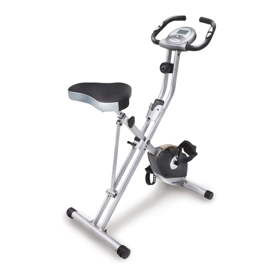
- Page 1 The s specificatio ons of this product m may vary fro om this pho oto, subjec ct to chang witho out notice. WNER R’S M MANU AL Item m #1200 ...
- Page 2 1200.2‐101414 ...
-
Page 3: Table Of Contents
TABLE OF CONTENTS SERVICE ------------------------------------------------------------------------ 2 LABEL PLACEMENT --------------------------------------------------------- 3 PRODUCT SAFETY ---------------------------------------------------------- 4 OVERVIEW DRAWING ------------------------------------------------------ 5 PARTS LIST --------------------------------------------------------------------- 6 HARDWARE LIST & TOOLS ----------------------------------------------- 8 ASSEMBLY --------------------------------------------------------------------- 9 COMPUTER --------------------------------------------------------------------- 13 STORAGE ----------------------------------------------------------------------- 14 ADJUSTMENTS --------------------------------------------------------------- 15 TROUBLE SHOOTING & MAINTENANCE ---------------------------- 17 WARM UP ---------------------------------------------------------------------- 18 WARRANTY -------------------------------------------------------------------- 19 FAX FORM ---------------------------------------------------------------------- 20... -
Page 4: Service
SERVICE IMPORTANT: FOR NORTH AMERICA ONLY To request product service and order replacement parts, please call our customer service department at: 1-844-641-7921 Monday through Friday, 8:00 AM-5:00 PM Pacific Standard Time, service@paradigmhw.com or email us at: Please visit our website at www.paradigmhw.com. Please have the following information ready when requesting for service: Your name Phone number... -
Page 5: Label Placement
LABEL L PLACEM MENT... -
Page 6: Product Safety
PRODUCT SAFETY Basic precautions should always be followed, including the following safety instructions when using this equipment. Read all instructions before using this equipment. Read all the instructions in this manual and do warm up exercises before using this equipment. Before exercise, in order to avoid injuring the muscle, warm-up exercise of every position of the body is necessary. -
Page 7: Overview Drawing
OVERVIEW DRAWING... -
Page 8: Parts List
PARTS LIST Description Qty No. Description 001 Rear Frame 1 029 Hexagon Nut Cap M8 002 Front Frame 1 030 Curve Washer Ø8.2xØ22.2 003 Rear Stabilizer Ø50x1.5tx550L 1 031 Front Stabilizer Ø50x1.5tx550L 004 Handlebar Ø25 1 032 C-ring Ø10 005 Seat Post 1 033 Flat Washer Ø8.2xØ16.8 006 Seat Cushion 1 034 Nylon Nut M8... - Page 9 PARTS LIST Description Qty No. Description 058 Hexagon Socket Bolt M8x15 5 074 Spring Washer Ø6.2 059 Rubber Cushion 1 075 Screw M5x15 060 Washer Ø8.2x Ø25x2.0t 2 076 Hexagon Socket Bolt M8x40L 061 Flat Phillips Head Screw M6x10 6 077 Handlebar End Cap Ø25.4 Front Frame Support Tube End 062 Holder 1 078...
-
Page 10: Hardware List & Tools
HARDWARE LIST & TOOLS (14) Seat Height (29) Hexagon Nut Cap (22) Safety Pin Adjustment Knob 4 PCS 1 PC 1 PC (30) Curve Washer (33) Flat Washer (58) Hexagon Socket Bolt 4 PCS 3 PCS 3 PCS (74) Spring Washer (66) Screw (73) Hexagon Socket Bolt 4 PCS 2 PCS... - Page 11 SSEMBL Tool: Wrench 13-15 Front Stab bilizer (31) Transpor rt Wheel ar Stabilize er (3) nd up the b base of the e machine by separa ating the R ear and Fr ront Frame (1, 2 2). Pull th he Rear an nd Front Fr rames (1, 2 2) apart fro...
-
Page 12: Assembly
ASSEMBLY Tool: Wrench 13-15 Tool: Wrench 19MM 1 PCS Step 2 Loosen Nylon Nut (L)(86) and Nylon Nut (R)(87) from Left and Right Pedal (7) &(8) first. The Cranks, Pedals, Pedal Shafts and Pedal Straps are marked “R” for Right and “L” for Left. Insert the pedal shaft of Left Pedal (7) into threaded hole in the Left Crank (23). - Page 13 ASSEMBLY Allen Wrench Tool: Phillips Screwdriver Allen Wrench with Phillips Screwdriver Step 3 Align bolt holes on underside of Seat Cushion (6) with holes on top of Seat Post (5), then attach with three Flat Washers (33) and three Hexagon Socket Bolts (58).
- Page 14 ASSEMBLY Allen Wrench Tool: Phillips Screwdriver Allen Wrench with Phillips Screwdriver Step 4 Connect the Sensor Wire (15) from the Rear Frame (1) to the wire that comes from the Computer (9). Attach the Handlebar (4) into the Rear Frame (1) with four Hexagon Socket Bolts (73) and four Spring Washers (74).
-
Page 15: Computer
OMPUTE ECIFICATI IONS: ME ---------- -------------- -------------- -- 0:00-99 :59 MIN: S EED ------- -------------- -------------- -- 0.0-999 .9 ML/H STANCE --- -------------- --------------- -- 0.0-999 .9 ML LORIE ---- -------------- -------------- -- 0.0-999 .9 KCAL OMETER -------------- -------------- --- 0.0-999 .9 ML LSE -------- --------------... -
Page 16: Storage
STORAGE For your convenience, the bike can be folded up and placed in a storage area. Remove the Safety Pin (22) from the bike. Push the Rear and Front Frames (1, 2) together until they meet. Align pin holes for inserting the Safety Pin (22) then insert the removed Safety Pin (22) into the holes on the Rear and Front Frames (1, 2) to lock the frames in place. -
Page 17: Adjustments
ADJUSTMENTS Adjusting the Tension Control Knob To increase the tension, turn the tension control knob in a clockwise direction. To decrease the tension, turn the tension control knob in a counterclockwise direction. Adjusting the Seat Height Turn the seat height adjustment knob in a counterclockwise direction until the seat post can be slid up or down and then slide the seat post up or down direction to the suitable position. - Page 18 USTME usting the e Pedal St trap L mark e left pedal strap whic ch has L m marked on t the strap (s see Figure e 1). ap the three e hole end onto the in nside edge e of the left t pedal (see e Figures 2 2 and...
-
Page 19: Trouble Shooting & Maintenance
MAINTENANCE & TROUBLE SHOOTING MAINTENANCE Cleaning The bike can be cleaned with a soft clean damp cloth. Do not use abrasives or solvents on plastic parts. Please wipe your perspiration off the bike after each use. Be careful not to get excessive moisture on the computer display panel as this might cause an electrical hazard or electronics to fail. -
Page 20: Warm Up
WARM U adriceps S Stretch With h one hand d against a a wall for b balance, re ach behind u and pull y your right fo oot up. B Bring your h heel as clo to y your buttoc cks as poss sible. -
Page 21: Warranty
WARRANTY MANUFACTURER’S LIMITED WARRANTY Paradigm Health & Wellness warrants to the original purchaser that this product is free from defects in material and workmanship when used for the purpose intended, under the conditions that it has been installed and operated in accordance with Paradigm’s Owner’s Manual. -
Page 22: Fax Form
FAX FORM Paradigm Health & Wellness, Inc. PARTS REQUEST FAX FORM Please fax this form to (1-626-810-2166) OR YOU CAN EMAIL CUSTOMER SERVICE REQUESTS TO service@paradigmhw.com NAME: _______________________________________________________ ADDRESS: ____________________________________________________ CITY ______________ STATE ______________ ZIP ___________________ TELEPHONE: (Day) _____________________________________________ (Night) ____________________________________________ (Email Address) ____________________________________ SERIAL#: __________________________________________ MODEL#: __________________________________________...
Need help?
Do you have a question about the 1200 and is the answer not in the manual?
Questions and answers
How do you remove the console to check if wire connection is there?
To remove the console on the Exerpeutic 1200 to check the wire connection, detach the computer console from the top of the Rear Frame and verify the wire from the console is properly connected to the wire from the rear frame.
This answer is automatically generated