Table of Contents
Advertisement
Quick Links
Advertisement
Table of Contents

Related Manuals for Exerpeutic 1200.9-102416


Summary of Contents for Exerpeutic 1200.9-102416
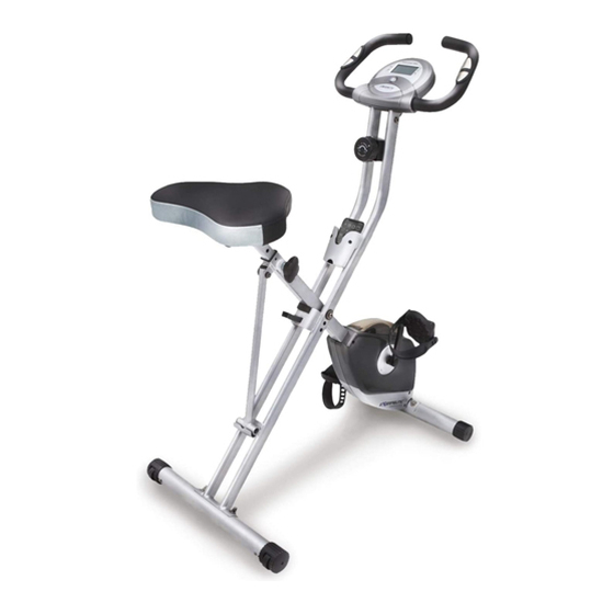
- Page 1 Folding Upright Bike with Pulse IMPORTANT: Read all instructions carefully before using this product. Retain this owner’s manual for future reference. The specifications of this product may vary from this photo, subject to change without notice. OWNER’S MANUAL 1200.9-102416...
- Page 2 PLEASE DO NOT RETURN THIS PRODUCT TO THE STORE. If you need help with product information, assembly, or replacement parts. Please contact customer service. Email us at: Service@paradigmhw.com Or call us at: 1-844-641-7921 Hours: 8:00 am to 5:00 pm (PST) Daily...
-
Page 3: Table Of Contents
TABLE OF CONTENT SERVICE ------------------------------------------------------------------------ -- LABEL PLACEMENT --------------------------------------------------------- -- IMPORTANT SAFETY GUIDELINES ------------------------------------- OVERVIEW DRAWING ------------------------------------------------------ -- PARTS LIST ---------------------------------------------------------------------- HARDWARE & TOOLS PACK ----------------------------------------------- ASSEMBLY --------------------------------------------------------------------- -- COMPUTER -------------------------------------------------------------------- -- STORAGE ----------------------------------------------------------------------- -- OPERATIONS & ADJUSTMENTS ------------------------------------------ TRANSPORTATION ------------------------------------------------------------ MAINTENANCE &... -
Page 4: Service
SERVICE IMPORTANT: FOR NORTH AMERICA ONLY For damaged or defective product, questions, replacement parts or any other service support, please contact our customer service department (8:00 AM - 5:00 PM Pacific Standard Time, Daily) by the below methods: For The Best Service, please Email: service@paradigmhw.com Response Time: 1-2 Business Days Emailing us with the information above will be the best method to receive a response during... -
Page 5: Label Placement
LABEL PLACEMENT... -
Page 6: Important Safety Guidelines
IMPORTANT SAFETY GUIDELINES Basic precautions should always be followed, including the following safety guidelines when using this equipment. Read all of the guidelines before using this equipment. 1. Before exercising and to avoid injuring your muscles, it is highly recommended that you perform warm-up exercises for each muscle group. - Page 7 IMPORTANT SAFETY GUIDELINES Do not use this equipment if you have any of the following conditions or ailments: • Pregnancy • Extreme obesity • Middle ear infection • Hiatus hernia or Ventral hernia • Glaucoma, retinal detachment or conjunctivitis • Use of anticoagulants including Aspirin in high doses.
-
Page 8: Overview Drawing
OVERVIEW DRAWING... -
Page 9: Parts List
PARTS LIST Description Description 01 Rear Frame 29 Hexagon Nut Cap M8 02 Front Frame 30 Curve Washer Ø8.2xØ22.2 03 Rear Stabilizer Ø50x1.5tx550L 31 Front Stabilizer Ø50x1.5tx550L 04 Handlebar Ø25 32 C-ring Ø10 05 Seat Post 33 Flat Washer Ø8.2xØ16.8 06 Seat Cushion 34 Nylon Nut M8 07 Left Pedal (YH-30X) - Page 10 PARTS LIST Description Description 58 Hexagon Socket Bolt M8x15 75 Screw M5x15 59 Rubber Cushion 76 Hexagon Socket Bolt M8x40L 60 Washer Ø8.2x Ø25x2.0t 77 Handlebar End Cap Ø25.4 Front Frame Support Tube End 61 Flat Phillips Head Screw M6x10 Cap Ø22.2 62 Holder 79 Hand Pulse Sensor Wire...
-
Page 11: Hardware & Tools Pack
HARDWARE & TOOLS PACK... -
Page 12: Assembly
ASSEMBLY Tool: 13-15mm Wrench Step 1 Stand up the base of the Rear and Front Frames (1, 2) by pulling them apart from each other. Rest the Support Tube (67) into the hooked plate on the Rear Frame (1). Align the upper pin holes on both frames and then insert the Safety Pin (22) into the uppers holes on the Rear and Front Frames (1, 2) to lock the frames in place. - Page 13 ASSEMBLY Tool: 13-15mm Wrench 19mm Wrench Step 2 Remove the Nylon Nut (L) (86) and Nylon Nut (R) (87) from the Left and Right Pedal (7) & (8). Note: Only turn the pedals in the direction instructed. The left and right pedal will have different directions for installation.
- Page 14 ASSEMBLY Allen Wrench Tool: Phillips Screwdriver Allen Wrench with Phillips Screwdriver Step 3 The Seat Cushion (6) has 2 sets of adjustment holes. It is recommended that users between 5’1” – 5’6” use the holes towards the rear of the seat and users between 5’7” to 6’3” use the holes towards the front.
- Page 15 ASSEMBLY Allen Wrench Tool: Phillips Screwdriver Allen Wrench with Phillips Screwdriver Step 4 Connect the Sensor Wire (15) from the Rear Frame (1) to the wire that hangs from the Computer (9). Attach the Handlebar (4) onto the top of the Rear Frame (1) with four Hexagon Socket Bolts (73) and four Spring Washers (74).
-
Page 16: Computer
COMPUTER SPECIFICATIONS: TIME --------------------------------------- 0:00-99:59 MIN: SEC SPEED ------------------------------------ 0.0-999.9 ML/H DISTANCE ------------------------------- 0.0-999.9 ML CALORIE --------------------------------- 0.0-999.9 KCAL ODOMETER ----------------------------- 0.0-999.9 ML PULSE ------------------------------------ 40-240 BEATS/MIN COMPUTER FUNTIONS: AUTO ON/OFF: The computer will automatically turn on when exercise is detected. If you leave the computer idle for 4 minutes, the power will shut off automatically. -
Page 17: Storage
STORAGE For your convenience, the bike can be folded up for storage. Remove the Safety Pin (22) from the upper pin hole of the bike. Fold the Rear Frame (1) and the Front Frame (2) together until the lower pin holes are aligned. -
Page 18: Operations & Adjustments
OPERATION & ADJUSTMENTS Adjusting the Tension Control Knob To increase the tension, turn the Tension Control Knob (13) in a clockwise direction. To decrease the tension, turn the Tension Control Knob (13) in a counterclockwise direction. Adjusting the Seat Height Turn the Seat Height Adjustment Knob (14) in a counterclockwise direction until the Seat Post (5) can be slid up or down and then slide the Seat Post (5) up or down to a suitable position. - Page 19 OPERATION & ADJUSTMENTS Adjusting the Pedal Strap L mark The Left Pedal Strap (88) is marked with an L on the strap. See Figure 1. Snap the three hole end onto the inside edge of the Left Pedal Strap (88) (see Figures 2 and 3). Select one of the adjustment holes which allow your foot to be easily removed from the pedal.
- Page 20 OPERATION & ADJUSTMENTS Allen Wrench Tool: Phillips Screwdriver Allen Wrench with Phillips Screwdriver Seat Cushion Adjustment The Seat Cushion (6) can be adjusted for users of different heights. Adjust the Seat Cushion (6) to the B position for people whose height is between 5’1” to 5’6”. Assemble the Seat Cushion (6) and align the bolt holes on the underside of Seat Cushion (6) with the holes on top of the Seat Post (5).
-
Page 21: Transportation
TRANSPORTATION Transporting the Bike Hold the Handlebar (4) and pull the machine until the wheels on the Front Stabilizer (31) make contact with the floor. Push or pull the unit to the desired location, then gently lower the Rear Stabilizer (3) to the ground. -
Page 22: Maintenance & Troubleshooting
MAINTENANCE & TROUBLESHOOTING MAINTENANCE Cleaning The bike can be cleaned with a soft clean damp cloth. Do not use abrasives or solvents on the plastic parts. Wipe your perspiration off the bike after each use. Be careful not to get excessive moisture on the computer display panel as this might cause an electrical hazard or electronics to fail. -
Page 23: Warranty
MAINTENANCE & TROUBLESHOOTING MANUFACTURER’S LIMITED WARRANTY Paradigm Health & Wellness warrants to the original purchaser that this product is free from defects in material and workmanship when used for the purpose intended, under the conditions that it has been installed and operated in accordance with Paradigm’s Owner’s Manual. -
Page 24: Part Request Form
PARTS REQUEST FORM Paradigm Health & Wellness, Inc. EMAIL THIS FORM WITH YOUR RECEIPT OF PURCHASE TO Service@paradigmhw.com NAME:_____________________________________________________________________________________ ADDRESS:__________________________________________________________________________________ CITY:________________________ STATE:_____________ ZIP:_______________________________________ TELEPHONE: (Day)________________________________________________________________________ (Night)_______________________________________________________________________ SERIAL#:___________________________________________________________________________________ MODEL#:___________________________________________________________________________________ PURCHASE DATE:___________________________________________________________________________ PLACE OF PURCHASE:_______________________________________________________________________ PART # DESCRIPTION “YOUR ORDER WILL BE PROCESSED WITHIN 3 BUSINESS DAYS” * This form can also be faxed in Fax #: 626-810-2166...
Need help?
Do you have a question about the 1200.9-102416 and is the answer not in the manual?
Questions and answers