Table of Contents
Advertisement
Advertisement
Table of Contents

Subscribe to Our Youtube Channel
Related Manuals for Custom Engineering VKP80II


Summary of Contents for Custom Engineering VKP80II
- Page 1 VKP80 VKP80 II II USER MANUAL DOMC-0011e Command Reference:...
- Page 2 All rights reserved. Total or partial reproduction of this manual in whatever form, whether by printed or electronic means, is forbidden. While guaranteeing that the information contained in it has been carefully checked, CUSTOM ENGINEERING SPA and other entities utilized in the realization of this manual bear no responsibility for how the manual is used.
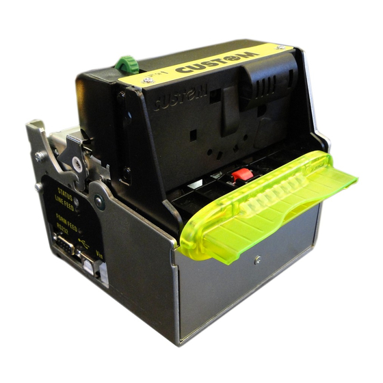
- Page 3 PRINTER COMPONENTS A. VKP80II - Front external view 1 - Opening lever 2 - Serial connector RS232 3 - USB connector 4 - Power supply connector 5 - Output paper mouth 6 - Cutter VKP80II User Manual...
- Page 4 B. VKP80II – Rear external view 1 - Left paper mouth cursor 2 - Paper input 3 - Right paper mouth cursor 4 - Form Feed key 5 - Line Feed key 6 - Status led VKP80II User Manual...
-
Page 5: Table Of Contents
A.1 ACCESSORIES ............................. A-1 A.1.1 Power Supply ..........................A-1 A.1.2 CD Full driver ..........................A-2 A.1.3 Adjustable paper holder support ....................A-2 A.2 SUPPLIES.............................. A-8 A.3 NOTES FOR TECHNICAL ASSISTANCE ....................A-9 A.3.1 Replacing fuse ..........................A-9 VKP80II i User Manual... - Page 6 B.3.1 Dimensions and position of the notch.................... B-6 B.3.2 Position of sensors ......................... B-8 B.3.3 Dimension of tickets ........................B-9 B.4 METHODS OF USAGE ........................B-10 B.4.1 Command sequences ........................ B-10 B.4.1.1 Alignment at the cut ........................B-10 B.4.1.2 Alignment at printing ........................B-11 ii VKP80II User Manual...
-
Page 7: Introduction
The printer is not functioning normally despite the fact that all instructions in the users ma nual have been followed. The printer has been dropped and its outer casing damaged. Printer performance is poor. The printer is not functioning. VKP80II 1 User Manual... -
Page 8: Unpacking The Printer
Take out the foam packing shell • Take out the printer and remove it from its plastic covering. • Keep the box, trays and packing materials in the event the printer must be transported/shipped in the future. 2 VKP80II User Manual... -
Page 9: Printer Features
INTRODUCTION PRINTER FEATURES VKP80II is the latest generation of ATMs, Kiosks and Ticket Printers with high printing speed 220mm/sec and a very small footprint; it’s equipped with a 204 dpi (8 dots/mm) thermal printing mechanism. In addition to normal printing functions, the printer offers a wide array of special features: •... - Page 10 Command reception time out Recovering error Nr. Flashings Description Heading over temperature Flashing Yellow Paper end Paper jam Power supply voltage incorrect Cover opened Unrecovering error Nr. Flashings Description Flashing RAM error EEPROM error Cutter error (Tab.1) 4 VKP80II User Manual...
-
Page 11: Installation And Use
Fig. 1.1). The connector pin confi guration is as follows : (Fig.1.1) Model no. type: Header : 90° Molex series 5569 (no. 39-30-1020) Housing: Molex series 5557 (no. 39-01-3022) SIGNAL +24 V (Tab.1.1) WARNING: Respect power supply polarity. VKP80II 1-1 User Manual... -
Page 12: Self-Test
Under PAPER PRINTED is given the number of centimetres of paper printed. • Under CUT COUNTER is given the number of cuts made. • Under RETRACT COUNTER is given the number of retract made. • Under POWER ON COUNTER is given the number of power-ups made. 1-2 VKP80II User Manual... -
Page 13: Printer Setup
It must be enabled only if it was installed the Status Monitor specifi c driver. If the “Notch Alignment” parameter is “Disabled” this parameter doesn’t appear in the “Printer Setup” ticket. VKP80II 1-3 User Manual... -
Page 14: Configuration
6E 20 30 31 32 33 34 35 36 37 38 39 20 61 62 63 64 65 66 67 68 69 6A 6B n 0123456789 abcdefghijk 0x000030 6C 6D 6E 6F 70 71 72 73 74 75 76 77 78 79 7A 2E lmnopqrstuvwxyz. 1-4 VKP80II User Manual... -
Page 15: Maintenance
Fig.1.6 gives alignment specifi cations for correct paper loading if no roll holder support is present. (Fig.1.4) 90° 90° 90° 90° (Fig.1.5) WARNING Before inserting the paper, make sure the cut is straight (see fi g.1.4). VKP80II 1-5 User Manual... -
Page 16: Ticket Specifi Cations
Below the right slide there are four point of reference for paper width (60, 70, 80 and 82.5mm). Move the slides to align the internal side of the fi n (A) with the point of reference. (Fig.1.6) 1-6 VKP80II User Manual... -
Page 17: Periodic Cleaning
The printer inside needs a periodic cleaning. Check the inside of the printer While pushing the opening lever down, lift the head/cutter unit (see fi g.1.7 and fi g.1.8) until it locks into posi- tion. (Fig.1.7) 90° max (Fig.1.8) VKP80II 1-7 User Manual... - Page 18 (D). Clean carefully the paper sensor (B) and the notch sensor (C). To clean, do not use harsh chemical solvents; the use of a soft, alcohol-moistened cloth and pneumatics air is recommended (see fi g.1.10) (Fig.1.9) (Fig.1.10) 1-8 VKP80II User Manual...
- Page 19 1. INSTALLATION AND USE WARNING To close the head/cutter unit: 1) push the opening lever down (see fi g.1.11); 2) lower the head/ cutter unit and press hard in the position shown in fi g.1.12. (Fig.1.11) (Fig.1.12) VKP80II 1-9 User Manual...
-
Page 20: Notes For Installation And Use Of Printer With Retracting
N.B.: “Ejector outfeed”: When assembling the printer on the machine, be sure to leave ad- equate space for the paper loop below. If this is not done, the ticket could crease at the cutting area, causing the ticket to jam in the paper outfeed opening. 1-10 VKP80II User Manual... -
Page 21: Notes For Installation And Lower Fastening Of Printer
3 FIXING POINT (BOTTOM) (Fig.1.14) +0.5 +0.5 85.5 -0.5 -0.5 ATTENTION It’s very important to consider the screws length to not damage the internal sensor board near the lower fi xing holes (see fi g. 1.15). VKP80II 1-11 User Manual... - Page 22 N.B.: The reference (1) indicates the screws that must located in the two external holes in front of the printer; the reference (2) indicates the screw that must located in the center hole of the rear side of the printer. 1-12 VKP80II User Manual...
-
Page 23: Interfaces
Not connected Signal Ground Ready to send. Printer on and operational (active with RS232 level high) N.C. N.C. Not connected Ready to send. Ready to receive data (active with RS232 level high) N.C. N.C. Not connected VKP80II 2-1 User Manual... - Page 24 2. INTERFACES The diagrams below illustrate a sample connection between the printer and PC using a 25- or 9-pin female connector. (Fig.2.2) VKP80II 2-2 VKP80II User Manual...
-
Page 25: Usb Interface
“Receptacle series B” - type connector. Refer to the table below for the connector pin signals and connection to a device: SIGNAL DESCRIPTION VBUS N.C. Data - Data + Ground signal Shield Cable shield (Tab.2.2) Shell VKP80II 2-3 User Manual... - Page 26 2. INTERFACES Blank page 2-4 VKP80II User Manual...
-
Page 27: Technical Specifications
For ticket width = 60 mm do not exceed a max length of 250 mm. Referred to model without paper holder support. It’s better to use an external shock absorber for rolls with a diameter higher than or equal to 100 mm. Referred to model without paper holder support. VKP80II 3-1 User Manual... - Page 28 10 mm - 30 mm Ejecting function Ticket length Ticket presentation 70 mm 10 mm > 80 mm 10 mm - 30 mm 350 mm 10 mm - 30 mm Maximum length recommended to guarantee the printer effi ciency. NOTE: 3-2 VKP80II User Manual...
-
Page 29: Dimensions
3. TECHNICAL SPECIFICATIONS 3.2 DIMENSIONS In the following fi gures shows the dimensions of the printer. 3 FIXING POINT (BOTTOM) Bottom view (Fig. 3.1) +0.5 +0.5 85.5 -0.5 -0.5 Top view (Fig. 3.2) VKP80II 3-3 User Manual... - Page 30 3. TECHNICAL SPECIFICATIONS Front view (Fig. 3.3) 123.5 Left side view (SX) (Fig. 3.4) 125.5 149.5 3-4 VKP80II User Manual...
-
Page 31: Character Sets
PC860, PC863, PC865, PC858. Shown below in fi gures 4.1 are examples of the 11 cpi character set. PC437 (Usa, Standard, Europe) PC850 (Multilingual) PC860 (Portuguese) PC863 (Canadian, French) PC865 (Nordic) PC858 (Euro symbol) (Fig.4.1) To print the Euro (€) symbol, the command sequence is: $1B, $74, $13, $D5. VKP80II 4-1 User Manual... - Page 32 4. CHARACTER SETS Blank page 4-2 VKP80II User Manual...
-
Page 33: Appendix A - Accessories And Spare Parts
0A ÷ 4,5A Effi ciency Operating temperature 0°C ÷ 70°C Environmental condition Humidity 20% ÷ 85% Rh (w/o condensation) Storage temperature / Humidity -10°C ÷ 75°C/ 10% ÷ 95% (w/o condensation) Protection devices: Shortcircuit, overload and overvoltage. VKP80II A-1 User Manual... -
Page 34: Cd Full Driver
An adjustable paper holder support kit (see fi g. A.2) is available for the printer to make it possible to use larger-width rolls of paper (130mm max.). PCXSP-VKP80II Paper roll holder kit with sensor for VKP80II The kit includes (see fi g. A.2) : 1 Tie for roll blocking... - Page 35 The position of the roll holder support is not fi xed and its rear, lower and upper position may be adjusted. The support is attached to the printer frame at four points, as shown in fi gure A.3. (Fig.A.3) UPPER ATTACHMENT REAR ATTACHMENT LOWER ATTACHMENT VKP80II A-3 User Manual...
- Page 36 Attach the paper holder support (4) to the printer body (1) using four M4x8 screws (5) supplied with the kit (see fi g. A.5). Insert the near paper end sensor connector (3) of the paper holder support into the connector of the sen- sor card located on the printer (6) (see fi g. A.5). A-4 VKP80II User Manual...
- Page 37 Put the paper holder support near the printer body. Insert the point of reference (2) (paper holder sup- port) into the hole (7) (printer body) (see fi g. A.7). Attach the paper holder support (4) to the printer body (1) using four M4x8 screws (5) supplied with the kit (see fi g. A.7). VKP80II A-5 User Manual...
- Page 38 Attach the paper holder support (4) to the printer body (1) using four M4x8 screws (5) supplied with the kit (see fi g. A.9). Insert the near paper end sensor connector (3) of the paper holder support into the connector of the sen- sor card located on the printer (6) (see fi g. A.9). A-6 VKP80II User Manual...
- Page 39 (see fi g. A.11). (Fig.A.11) “Tie” for roll blocking Insert the “tie” as shown in fi gure A.12 to avoid the paper roll come out accidentally from the pin. (Fig.A.12) VKP80II A-7 User Manual...
-
Page 40: Supplies
Printer dimensions with roll holder support +0.5 +0.3 85.5 -0.5 -0.3 (Fig.A.13) M4; no. 3 holes 61.8 306.2 17.3 A.2 SUPPLIES 80mm thermal paper roll back side pre-printed RCT80X48-25MM-RS Paper roll with paper holder support Thermal paper roll 80mm RCT80X130-25MM A-8 VKP80II User Manual... -
Page 41: Notes For Technical Assistance
Unscrew the two fi xing screw for the back closing. Move back closing down and then remove as shown in fi g. A. 14. • Unscrew the two screws that fi xing control board to the chassis as shown in fi g. A.15. (Fig.A.14) (Fig.A.15) VKP80II A-9 User Manual... - Page 42 • Replace the fuse with a new one with same specifi cations (4A, 125V) and place it again in its seating. • Reassemble the printer. (Fig.A.16) (Fig.A.17) (Fig.A.18) A-10 VKP80II User Manual...
-
Page 43: Appendix B - Alignment Management
In order to better identify the optimum threshold for the paper being used, a paper characterisation function is also available in setup. :Yes Characterize Paper. By activating this parameter the outgoing voltage of the sensor will be presented in a graphic form as shown in fi gure B.1 below: VKP80II B-1 User Manual... - Page 44 32 mm. In reality the maximum distance corresponds to the mechanical distance between the notch sensor and the head, and it is for this reason that higher values are not permitted, and negative values are not envisaged. B-2 VKP80II User Manual...
-
Page 45: Commands
TICKET $1D,$E7,$00,$00, FIRST LINE SECOND LINE {Print text} ‘TICKET 1’,$0A,’FIRST LINE’,$0A,’SECOND LINE’,$0A {Cut alignment} $1D, $F8, {Cut} ESC,’i’, {Print text} ‘TICKET 1’,$0A,’FIRST LINE’,$0A,’SECOND LINE’,$0A TICKET (N+1) {Cut alignment} FIRST LINE $1D,$F8, SECOND LINE {Cut} ESC,’i’, (Fig.B.3) VKP80II B-3 User Manual... - Page 46 {Set Notch Distance} $1D,$E7,$00,$00, TICKET {Print text} FIRST LINE ‘TICKET 1’,$0A,’FIRST LINE’,$0A,’SECOND LINE’,$0A SECOND LINE {Cut} ESC,’i’ {Set Notch Distance} $1D,$E7,$00,$00, TICKET (N+1) {Print text} FIRST LINE ‘TICKET 1’,$0A,’FIRST LINE’,$0A,’SECOND LINE’,$0A SECOND LINE {Cut} ESC,’i’, (Fig.B.5) B-4 VKP80II User Manual...
- Page 47 {Set Notch Distance} $1D,$E7,$00,$00, SECOND LINE {Print text} ‘TICKET 1’,$0A,’FIRST LINE’,$0A,’SECOND LINE’,$0A {Cut alignment} $1D, $F8, {Cut} ESC,’i’, TICKET (N+1) {Print text} FIRST LINE ‘TICKET 1’,$0A,’FIRST LINE’,$0A,’SECOND LINE’,$0A SECOND LINE {Cut alignment} $1D,$F8, {Cut} ESC,’i’, (Fig.B.6) VKP80II B-5 User Manual...
-
Page 48: Characteristics Of The Paper
NON HEAT SENSITIVE Side Direction Black notch of paper (Fig.B.7) feed Notch sensor axis Notch on 75 mm paper +0,5 -0,5 NON HEAT SENSITIVE Side 16,5 Black notch Direction Notch sensor axis of paper (Fig.B.8) feed B-6 VKP80II User Manual... - Page 49 NON HEAT SENSITIVE Side Black notch Direction Notch sensor axis of paper (Fig.B.9) feed Notch on 82,5 mm paper 82,5 +0,5 -0,5 NON HEAT SENSITIVE Side 20,25 Direction Black notch of paper (Fig.B.10) feed Notch sensor axis VKP80II B-7 User Manual...
-
Page 50: Position Of Sensors
32 mm upstream of the of the notch in order therefore for it to align itself with this notch, as a refer- ence the paper can only be fed forward, and so reduce the distance already there. B-8 VKP80II User Manual... -
Page 51: Dimension Of Tickets
LEGEND: A = Alignment feed H = Printing area height B = Non printable area (CUTTER - PRINT HEAD) PAPER IN TICKET THE PRINTER PRODUCED Direction of paper Printing area (Fig.B.12) VKP80II B-9 User Manual... -
Page 52: Methods Of Usage
At the end of the print area the printer has fed the paper through to align itself and perform the cut at the desired position. B-10 VKP80II User Manual... -
Page 53: Alignment At Printing
The result is shown in fi gure B.14. Unlike the previous case, the alignment feed takes place before the start of printing, so as to align the print area in the position required. CUTTER PRINT HEAD PAPER IN THE PRINTER Printed area (Fig.B.14) VKP80II B-11 User Manual... - Page 54 APPENDIX B - ALIGNMENT MANAGEMENT Blank page B-12 VKP80II User Manual...
- Page 56 CUSTOM ENGINEERING SPA World Headquarters Via Berettine, 2 - 43010 Fontevivo, Parma ITALY Tel. +39 0521 680111 - Fax +39 0521 610701 info@custom.biz - www.custom.biz All rigths reserved www.custom.biz...
Need help?
Do you have a question about the VKP80II and is the answer not in the manual?
Questions and answers