Table of Contents
Advertisement
Advertisement
Table of Contents

Related Manuals for Custom Engineering KPM 216H II


Summary of Contents for Custom Engineering KPM 216H II
- Page 1 KPM 216H II KPM 216H II USER MANUAL DOMC-0005e Command Reference:...
- Page 2 All rights reserved. Total or partial reproduction of this manual in whatever form, whether by printed or elec- tronic means, is forbidden. While guaranteeing that the information contained in it has been carefully checked, CUSTOM ENGINEERING SPA and other entities utilized in the realization of this manual bear no responsibility for how the manual is used.
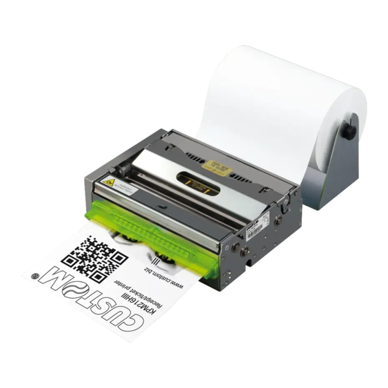
- Page 3 PRINTER COMPONENTS A. KPM216H-II Front external view 1- Printing head set 2- Opening lever of head set 3- Roller cover 4- Paper exit 5- Lock/Unlock button of motorization cover 6- Motorization cover (1) : NOTE Available in two versions: horizontal or vertical (option 0090) paper delivery KPM216H II User Manual...
- Page 4 B. KPM216H-II - Rear external view 1- Paper load 2- Paper feed guides (adjustable) 3- Status led 4- Feed key 5- Print key 6- Reset key 7- External near paper end sensor connector 8- Motorization cover 9- Printing head set 10- Opening lever of head set 11- Tilting paper holder 12- Paper ejector rollers unit...
- Page 5 C. KPM216H-II Under view KPM216H II-E model 1- Power supply fuse 2- Power supply connector 3- RS232 serial interface connector 4- ETHERNET connector 5- USB interface connector KPM216H II User Manual...
- Page 6 Blank page KPM216H II User Manual...
-
Page 7: Table Of Contents
TABLE OF CONTENTS INTRODUCTION MANUAL CONTENTS ............................1 EXPLANATORY NOTES USED IN THIS MANUAL ..................1 GENERAL SAFETY INFORMATION ........................ 1 UNPACKING THE PRINTER ........................... 2 PRINTER FEATURES ............................3 PRINTER DESCRIPTION ..........................4 1. INSTALLATION AND USE 1.1 CONNECTIONS ............................1-1 1.1.1 Power Supply ..........................1-1 1.2 ADDITIONAL BRACKETS ASSEMBLING ....................1-2 1.3 SELF-TEST .............................1-4... - Page 8 TABLE OF CONTENTS APPENDIX B - ALIGNMENT MANAGEMENT B.1 TICKET ALIGNMENT ..........................B-1 B.1.1 Ticket alignment ..........................B-1 B.1.2 Enabling, calibrating and setting of parameters................B-1 B.2 COMMANDS ............................B-3 B.2.1 Ticket alignment..........................B-3 B.2.2 Setting the alignment distance....................... B-3 B.2.3 Examples ............................
-
Page 9: Introduction
INTRODUCTION MANUAL CONTENTS In addition to the Introduction which includes a description of the explanatory notes used in the manual, general safety information, how to unpack the printer and a brief description of the printer including its basic features, this manual is organized as follows: Chapter 1: Contains the information required for correct printer installation and its proper use . -
Page 10: Unpacking The Printer
INTRODUCTION UNPACKING THE PRINTER Rimuovete la stampante dal cartone, facendo attenzione a non danneggiare il materiale di imballaggio al fi ne di utilizzarlo per trasporti futuri. Assicuratevi che vi siano i componenti illustrati in seguito e che essi non siano danneggiati. In caso contrario contattare il servizio di assistenza. -
Page 11: Printer Features
INTRODUCTION PRINTER FEATURES It’s an A4/US letter format thermal printer designed for Internet, information and reservation kiosks and auto- matic teller (ATM) machines. It is available in two models: 204 dpi (8 dots/mm) thermal printing mechanism version and 300 dpi (11.8 dots/ mm) thermal printing mechanism version. - Page 12 INTRODUCTION (Tab.1) STATUS LED COLOUR DESCRIPTION Turned ON GREEN Printer ON : no error Communication status Nr. fl ashings Description Receive data Flashing GREEN Reception errors (parity, frame error, overrun error) Misinterpret command Command reception time out Recovering error Nr. fl ashings Description Heading over temperature Flashing...
-
Page 13: Installation And Use
1. INSTALLATION AND USE 1.1 CONNECTIONS (Fig.1.1) 1.1.1 Power Supply The printer is equipped with an external power supply outlet (see Fig. 1.1). The connector pin confi guration is as follows: Model no. type : Header : Molex 39-30-0060 (Vertical) Housing : Molex 39-01-2065 (Tab.1.1) -
Page 14: Additional Brackets Assembling
1. INSTALLATION AND USE This picture shows the power supply cable included in the printer packaging : BLACK (Fig.1.2) BLACK 6 PIN (3x2) OPPOSITE VIEW SIDE FEMALE CONNECTOR OF CABLE INSERTION The connector pin confi guration of this cable is as follows: (Tab.1.2) Female Cable Color... - Page 15 1. INSTALLATION AND USE Right side (dx) (Fig.1.3) Left side (sx) (Fig.1.4) KPM216H II 1-3 User Manual...
-
Page 16: Self-Test
1. INSTALLATION AND USE 1.3 SELF-TEST During power-up, if the LF LINE FEED key is held down, the printer enters the autotest routine and prints out the Setup report (see fi g.1.5). The printer will remain in standby in Hexadecimal dump mode (see par.1.5) until another key is pressed or characters are received through the printer communication port. -
Page 17: Configuration
1. INSTALLATION AND USE NOTE: : Parameter valid only with serial interface. : Parameter valid only with serial interface; using this parameter, it is possible to select whether the Busy signal is activated when the printer is both in Off Line status and the buffer is full, or only if the reception buffer is full. : This parameter is present in the version with release higher than 1.00. - Page 18 1. INSTALLATION AND USE (Fig.1.6) Notch Position ......: Low Side P ap ....: 3 30% Alignm ..........: P ap Buff f er Clear ....: Short Ticket (< (<150 150mm) .... Di Disab sabled Print Density..
-
Page 19: Printer Setup
1. INSTALLATION AND USE To change this value is possible to modify the digits of each byte: byte byte byte byte 1° byte: digit digit digit where: digit: 0 - 2 digit; 3 digit: 0 - 9 The selected digit is highlighted (the number is written in negative mode). Press FORM FEED key to modify the value of the highlighted digit;... - Page 20 1. INSTALLATION AND USE (6) (7) • Notch Threshold : 30%, 40% , 50%, 60%, 70%, 80%, 90%. (6) (8) • Notch Dist. Signum , -. • Notch Dist. [mm x 10] (6) (8) , 1, 2, 3, 4, 5, 6, 7, 8, 9. (6) (8) •...
-
Page 21: Hexadecimal Dump
1. INSTALLATION AND USE 1.5 HEXADECIMAL DUMP This function is used to diagnose the characters received through the communication port; the characters are printed out both as hexadecimal codes and ASCII codes (see fi g. 1.9). Once the self-test routine has fi nished, the printer enters Hexadecimal Dump mode. -
Page 22: Paper Load Specifi Cations
1. INSTALLATION AND USE WARNING Make sure the paper and printer are aligned (see fi g. 11 and fi g. 1.12). 1.6.2 Paper load specifi cations To correctly load the paper, follow the alignment instructions shown in fi gs. 1.11 and 1.12. (Fig.1.11) CROSS SECTION VIEW OF FRONTAL PANEL FROM... -
Page 23: Adjusting Paper Width
1. INSTALLATION AND USE 1.6.3 Adjusting paper width Paper width may be adjusted from 194mm to 216mm using the right (Dx) and Left (Sx) slides located at the paper infeed opening. Move the right and left slides to adjust the paper width (see fi g. 1.13). (Fig.1.13) S t a t u s... -
Page 24: Paper Jam
1. INSTALLATION AND USE 1.6.4 Paper Jam In the event of a jam along the paper path, proceed as follows: turn the printer off and on, before removing the paper, in order to cut the paper and attempt to have it ejec- ted. - Page 25 1. INSTALLATION AND USE Paper jammed inside the printer perform the operations below: 1) Lift up the print head using the opening slot (1) located on the cover (see fi g. 1.15); remove any pieces of paper. (Fig.1.15) (10) 2) Open the lateral cover (1) rotating the lock/unlock button (2) with the screwdriver or coin (see fi...
- Page 26 1. INSTALLATION AND USE Extract the cover unit pulling from the bottom to the outside and then lifting up to release the two slots (see fi g.1.17). (Fig.1.17) 4) Pulling up the cutter as shown in the fi g. 1.18 (Fig.1.18) remove any pieces of paper.
-
Page 27: Cleaning The Printing Head
1. INSTALLATION AND USE 1.6.5 Cleaning the printing head WARNING • Do not touch the head heating line with bare hands or metal objects. • Do not perform any operation inside the printer immediately after printing because the head and motor tend to become very hot. •... -
Page 28: Cleaning The Ejector Rollers
1. INSTALLATION AND USE 3) Lower the cover (1) to close and pressing (2) in the exact point indicated from the label located on the cover as shown in the fi g. 1.21 e 1.22. (Fig.1.21) (Fig.1.22) 1.6.6 Cleaning the ejector rollers WARNING •... -
Page 29: Memory Card Insertion
1. INSTALLATION AND USE 1.6.7 Memory card insertion WARNING • The printer must be turned off during cleaning operations. To memory card insertion get access to the control board located inside the printer under the cutter, as shown in the fi g. 1.24. To access to the control board referred to paper jam paragraph and follow the indica- tions and the fi... -
Page 30: Ticket Characteristics
1. INSTALLATION AND USE 1.7 TICKET CHARACTERISTICS 1.7.1 Ticket characteristics It’s possible to use paper with alignment mark. The fi gure 1.26 shows paper with alignment mark fac-simile; the notch distance in mm from the beginning of the document must be setting during the printer setup. (Fig.1.26) PAPER OUTFEED DIRECTION Thermal side... -
Page 31: Interfaces
2. INTERFACES 2.1 RS232 SERIAL RS232 (Fig.2.1) The printer has an RS232 serial interface and is connected by means of a 9 pin female connector (see fi g. 2.1). In the following table, the signals present on the connector are listed: (Tab.2.1) SIGNAL IN / OUT... - Page 32 2. INTERFACES The following diagrams show examples of connections between the printer and the Personal Computer using 25 and 9 pin female connectors. (Fig.2.2) PRINTER PRINTER 2-2 KPM216H II User Manual...
-
Page 33: Ethernet Interface
2. INTERFACES 2.2 ETHERNET INTERFACE The printer with Ethernet interface is equipped with a 8-pin RJ45 connector. (Fig.2.3) “SX” “DX” RJ45 Refer to the table below for the connector pin signals: (Tab.2.2) SIGNAL DESCRIPTION ETX+ ETX+ ETX- ETX- ERX+ ERX+ N.C. -
Page 34: Usb Serial Interface
2. INTERFACES 2.3 USB SERIAL INTERFACE (Fig.2.4) USB type B Printers with USB serial interface conform to USB 1.1 standards and have the following specifi cations: • Communication speed 12 Mbit/sec • “Receptacle series B” - type connector. Refer to the table below for the connector pin signals and connection to a device: SIGNAL DESCRIPTION (Tab.2.3) -
Page 35: Technical Specifications
3.TECHNICAL SPECIFICATIONS 3.1 TECHNICAL SPECIFICATIONS Table 3.1 gives the main technical specifi cations of the 200 dpi printer model. (Tab.3.1) Printing method Thermal, fi xed head (8 dot/mm) Resolution 204 DPI (8 dot/mm) Standard Interfaces RS232 Ethernet Communication speed 12 Mbit/sec from 1200 to 115200 bps 10 Mbit/sec PAPER SPECIFICATIONS Type of paper... - Page 36 3.TECHNICAL SPECIFICATIONS ENVIRONMENTAL CONDITIONS Operating temperature 0°C ÷ +50°C Relative humidity 10-85% Rh Storage temperature / humidity -20 °C – 70 °C / 10% - 90% Rh Weight [gr] (without paper roll) Options Roll holder support, 90° paper exit Emulation ESC/POS Minimum printable ticket 160mm...
- Page 37 3.TECHNICAL SPECIFICATIONS head temperature, autoload, near paper end, blackmark, paper pre- Sensors sence on cutter output, ticket presence on output, cover opening and motorization cover Printing mode Normal, 90°, 180°, 270° Printing format Height/Width from 1 to 8, bold, reverse, underlined, italic ESC/POS emulation: PC437, PC850, PC860, PC863, PC865, PC858 (euro).
-
Page 38: Dimensions
3.TECHNICAL SPECIFICATIONS 3.2 DIMENSIONS In the following fi gures shows the dimensions of the printer. Bottom view (Fig.3.1) (4 slots) Top view (Fig.3.2) 194-216 (paper input) 3-4 KPM216H II User Manual... - Page 39 3.TECHNICAL SPECIFICATIONS Rear view (Fig.3.3) 147,4 140,5 140,5 NOTE The part of vertical paper exit in the drawings is indicated with a dotted line, (model with 90° paper exit). Right-side view (Dx) (Fig.3.4) Paper Horizontal input paper output Vertical paper output 12,5 KPM216H II 3-5 User Manual...
- Page 40 3.TECHNICAL SPECIFICATIONS Left side view (Sx) with cover open (Fig.3.5) (Fig.3.6) Front view with cover open 20° WARNING! MOVING PARTS 3-6 KPM216H II User Manual...
- Page 41 3.TECHNICAL SPECIFICATIONS Paper outfeed direction In the following fi gures is showed the printer paper input (1) and paper output (2); in the fi g. 3.8 is illustrated the optional model with vertical paper exit. (Fig.3.7) (Fig.3.8) KPM216H II 3-7 User Manual...
- Page 42 3.TECHNICAL SPECIFICATIONS Blank page 3-8 KPM216H II User Manual...
-
Page 43: Character Sets
4. CHARACTER SETS 4.1 CHARACTER SETS IN ESC/POS EMULATION The printer has 3 fonts of varying width for the 204 dpi (11, 15 and 20 cpi) and 300 dpi (17, 23 and 30 cpi) models, which may be accessed through programming (section 1.2) or control characters (see command reference). -
Page 44: Character Sets In Svelta Emulation
4. CHARACTER SETS 4.2 CHARACTER SETS IN SVELTA EMULATION In SVELTA emulation the printer has 20 fonts of varying width which may be accessed through control cha- racters (see commands description in SVELTA emulation of Command Reference). The following list shows the font availables and relative dimensions in dot: •... -
Page 45: Appendix A - Accessories And Spare Parts
APPENDIX A - ACCESSORIES AND SPARE PARTS A.1 ACCESSORIES A.1.1 Power supply The fi gure below illustrates the power supply provided by Custom to be used for printer operation. (Fig.A.1) Dimensions in mm: BOTTOM VIEW (Tab.A.1) PPSPS-240-P24 Switching power supply 24V 240W Input AC Input 115V ~ 5.0A... -
Page 46: Spare Parts
APPENDIX A - ACCESSORIES AND SPARE PARTS A.2 SPARE PARTS RCT210X140-25MM 70 GR Thermal paper roll 210mm RCT216X140-25MM 70 GR Thermal paper roll 216mm A.3 NOTES FOR TECHNICAL ASSISTANCE ATTENTION: The operations here described are exclusively aimed to the personnel han- dling the technical assistance of the printer. - Page 47 APPENDIX A - ACCESSORIES AND SPARE PARTS Replace the belt and place it again between the two pulleys in its seating, as shown in fi g. A.3. (Fig.A.3) A.3.2 Replacing fuse on the control board ATTENTION: Before replacing the fuse, it’s important to check up that the supply cable of the printer is out.
- Page 48 APPENDIX A - ACCESSORIES AND SPARE PARTS The fuse is on the control board of the printer, near the power supply connector (see Fig.A.4). To replace the fuse before it’s necessary remove the protection cap over the fuse, lift up the protection cap using a tweezer (as shown in fi...
-
Page 49: Appendix B - Alignment Management
APPENDIX B - ALIGNMENT MANAGEMENT B.1 TICKET ALIGNMENT B.1.1 Ticket alignment Paper with an alignment notch can be used in order to handle tickets with pre-printed fi elds and a fi xed leng- To guarantee the alignment it is necessary that the “Notch Alignment” parameter is enabled from the key setup (see setting confi... - Page 50 APPENDIX B - ALIGNMENT MANAGEMENT (Fig.B.1) PAPER CHARACTERIZATION Notch Threshold N.B.: The outgoing voltage of the sensor will be presented in a graphic as a percentage value. The graphic shows the outgoing voltage of the sensor and the threshold value previously set. It is clear that by adjusting the threshold value it is possible to fi...
-
Page 51: Commands
APPENDIX B - ALIGNMENT MANAGEMENT B.2 COMMANDS B.2.1 Ticket alignment The commands to manage ticket alignment are present only in ESC/POSTM emulation; in SVELTA emula- tion are automatically performed with the printing commands <p> <P> <q> <Q>. In ESC/POS emulation the two alignment available commands are : $1D $F6 and $1D $F8. The command $1D $F6 performs an alignment to the print head: the paper is fed through until the print head is at the ticket start. - Page 52 APPENDIX B - ALIGNMENT MANAGEMENT Example 2 To cut 10mm before the notch the command sequence is (this setting have effect after the ticket already in the printer): $1D, $E7, $00, $0A, {Print text} TICKET ‘TICKET 1’,$0A,’FIRST LINE’,$0A,’SECOND LINE’,$0A FIRST LINE {Cut alligment} SECOND LINE...
-
Page 53: Printer Mechanical Characteristics
APPENDIX B - ALIGNMENT MANAGEMENT Example 4 To print 15mm before the notch the command sequence is (this setting have effect after the ticket already in the printer): TICKET {Set Notch Distance} FIRST LINE $1D,$E7,$00,$0F, SECOND LINE {Print head aligment} $1D, $F6, {Print text} ‘TICKET 1’,$0A,’FIRST LINE’,$0A,’SECOND LINE’,$0A... -
Page 54: Ticket Dimension
APPENDIX B - ALIGNMENT MANAGEMENT B.3.2 Ticket Dimension It is very important to well calibrate the height of the printer area, according to the distance between the two edges of the notch. In order not to miss a notch (a ticket must therefore contain only one notch) the following equation must be used: INTER-NOTCH DISTANCE>PRINTED AREA HEIGHT where... -
Page 55: Methods Of Usage
APPENDIX B - ALIGNMENT MANAGEMENT B.4 METHODS OF USAGE B.4.1 Command sequences It is possible, when printing sequences of tickets, to primarily identify three different methods of operation that involve the alignment: • ticket aligned at the cut, • ticket aligned at printing, •... - Page 56 APPENDIX B - ALIGNMENT MANAGEMENT Blank page B-8 KPM216H II User Manual...
-
Page 57: Appendix C - Advanced Functions
APPENDIX C - ADVANCED FUNCTIONS C.1 PRINTER SET-UP N.B. : The printer with release 1.00 doesn’t provide the Mass Storage; so alls references to this functionality in this chapter are not valid for the 1.00 printer release. C.1.1 Mass Storage activation One of the parameters related to printer confi... -
Page 58: Embedded Web Server
APPENDIX C - ADVANCED FUNCTIONS C.2 EMBEDDED WEB SERVER KPM216H II model with Ethernet interface, is equipped with an Embedded Web Server that allows to ex- ecute some operations on printers, through a clear web interface, including: • monitoring the printer status; •... -
Page 59: Embedded Web Server Access
APPENDIX C - ADVANCED FUNCTIONS C.2.2 Embedded Web Server access To enter the Embedded Web Server, type the IP address assigned to the printer into Web browser. For ex- ample, if IP address of the printer is 192.168.10.36, type in the Web browser: http://192.168.10.36 On the screen will appear the internal default page that corresponds to the section “Device Info”... -
Page 60: Embedded Web Server Functions
APPENDIX C - ADVANCED FUNCTIONS C.2.3 Embedded Web Server functions Status Monitor In the “Device Info” section, it is possible to display in real time the printer operating status using the follow- ing tools: • RealTime Status. • Model Information. •... - Page 61 APPENDIX C - ADVANCED FUNCTIONS The printer confi guration tools are: • Printer Setup. • Network Setup. • Email Setup. • Email Log. With these tools, it is possible to set up the same parameters of the printer that are confi gurable in the printer’s Set-up mode (see par.1.4).
- Page 62 APPENDIX C - ADVANCED FUNCTIONS (Fig.C.8) After making registration and obtaining the access to the restricted area (see fi g.C.8), it is possible to test some printer function (see fi g.C.9), for demonstrative and service purpose, as: • printing a test page, the font test and the logos test; •...
-
Page 63: Locator
APPENDIX C - ADVANCED FUNCTIONS C.3 LOCATOR For the models with Ethernet interface, it is available an external software (see fi g.C.10). The “Locator” is able to execute a search of the printers connected to the network with an Ethernet cable, without knowing the IP address of each printer. -
Page 64: Driver Windows/Linux
APPENDIX C - ADVANCED FUNCTIONS C.4 DRIVER WINDOWS / LINUX C.4.1 Driver download from Mass Storage To install printing drivers from USB Mass Storage, proceed as follows: Connect the printer to a computer by an USB cable (see fi g.C.12). (Fig.C.12) NOTE: To download drivers from USB Mass Storage, enable “USB Mass Storage”... -
Page 65: Drivers Download From Ftp Server
APPENDIX C - ADVANCED FUNCTIONS Copy printer drivers into the “Driver” folder (see fi g.C.14). (Fig.C.14) C.4.2 Driver download from FTP Server To install printing drivers by FTP Server connection, proceed as follows: Connect to the network the printer and the computer (see fi g.C.15). (Fig.C.15) NOTE: To download drivers from FTP Server, enable “FTP Server”... - Page 66 APPENDIX C - ADVANCED FUNCTIONS Type in the address bar “ftp://” followed by the IP address of the printer (see fi g.C.16) (Fig.C.16) NOTE: To know the IP address of the printer, print the Set-up report of the printer (see par.1.4.1) or use “Locator”...
-
Page 67: Drivers Download From Embedded Web Server
APPENDIX C - ADVANCED FUNCTIONS C.4.3 Driver download from Embedded Web Server To download printing driver from the Embedded Web Server, proceed as follows: Connect to the network the printer and the computer (see fi g.C.18). Enter into the Embedded Web Server following the instruction of the par.C.2.2. Enter into the “Printer Support”... -
Page 68: Logos Management
APPENDIX C - ADVANCED FUNCTIONS C.5 LOGOS MANAGEMENT With KPM216H it is possible to store new logos in addition to default logos stored on Flash Disk. The printer automatically provides to convert BMP image to the error-diffusion format in black and white. In the models with the SD/MMC card (see fi... - Page 69 APPENDIX C - ADVANCED FUNCTIONS Open printer’s Flash Disk and enter the internal folders (see fi g.C.23). (Fig.C.23) Copy the new logo into the “Pictures” folder (see fi g.C.24). (Fig.C.24) KPM216H II C-13 User Manual...
- Page 70 APPENDIX C - ADVANCED FUNCTIONS NOTE: In models with SD/MMC card, it is possible to store the new logo both on SD/MMC and on Flash Disk. 4. Add to the confi guration fi le “PictList.ini”, a line with a number associated to the logo (to be used with printer’s commands), a letter for the memory unit and the logo fi...
-
Page 71: Logos Management From Ftp Server
APPENDIX C - ADVANCED FUNCTIONS C.5.2 Logos management from FTP Server To add a new logo to the printer from FTP Server, proceed as follows: Connect to the network the printer and the computer (see fi g.C.26) (Fig.C.26) NOTE: To manage logos from FTP Server, enable “FTP Server” parameter into printer Set-up (see par.C.1.2). - Page 72 APPENDIX C - ADVANCED FUNCTIONS Copy the new logo into the “Pictures” folders (see fi g.C.28). (Fig.C.28) 4. Add to the confi guration fi le “PictList.ini”, a line with a number associated to the logo (to be used with printer’s commands), a letter for the memory unit and the logo fi le name, as indicated in the instructions writ- ten inside the “PictList.ini”...
-
Page 73: Logos Management From Embedded Web Server
APPENDIX C - ADVANCED FUNCTIONS C.5.3 Logos management from Embedded Web Server To manage logos from the Embedded Web Server, proceed as follows: Connect to the network the printer and the computer (see fi g.C.30). Enter into the Embedded Web Server following the instruction of the par.C.2.2. Enter into the “Printer Support”... -
Page 74: Logos Printing
APPENDIX C - ADVANCED FUNCTIONS After making registration (see par.C.2.2), the “Printer Settings” page will be displayed (see fi g.C.33). It is pos- sible to execute the following operations: • add a new logo, associate the added logo to an unambiguous number and select the unit memory of storage (Flash Disk or SD/MMC, for the model with SD/MMC);... - Page 75 APPENDIX C - ADVANCED FUNCTIONS Blank page KPM216H II C-19 User Manual...
- Page 76 CUSTOM ENGINEERING SPA World Headquarters Via Berettine, 2 - 43010 Fontevivo, Parma ITALY Tel. +39 0521 680111 - Fax +39 0521 610701 info@custom.biz - www.custom.biz All rigths reserved www.custom.biz...
Need help?
Do you have a question about the KPM 216H II and is the answer not in the manual?
Questions and answers