Table of Contents
Advertisement
Quick Links
Operation Manual
For Menu Screens
Thank you for purchasing our product.
This manual provides important information about safe and proper
operations of this Switching Hub.
Please read the "Important Safety Instructions" on pages 2 to 4.
Any problems or damage resulting from disassembly of this Switching
Hub by customers are not covered by the warranty.
Switch-M24PWR
Model Number: PN23249A
Advertisement
Table of Contents

Related Manuals for Panasonic M24PWR


Summary of Contents for Panasonic M24PWR
- Page 1 Switch-M24PWR Operation Manual For Menu Screens Model Number: PN23249A Thank you for purchasing our product. This manual provides important information about safe and proper operations of this Switching Hub. Please read the "Important Safety Instructions" on pages 2 to 4.
- Page 2 Important Safety Instructions This chapter contains important safety instructions for preventing bodily injury and/or property damage. You are required to follow them. Severity of bodily injury and/or property damage, which could result from incorrect use of the Switching Hub, are explained below. WARNIN This symbol indicates a potential hazard that could result in serious injury or death.
- Page 3 WARNIN Do not install this Switching Hub at the location with continuous vibration or strong shock, or at the unstable location Deviation could lead to injury and/or equipment failure. Do not install any module other than the separately sold SFP module to SFP extension slot.
-
Page 4: Basic Instructions For The Use Of This Product
Basic Instructions for the Use of This Product For inspection and/or repair, consult the retailer. Use commercial power supply from a wall socket, which is close and easily accessible to this Switching Hub. Unplug the power cord when installing or moving this Switching Hub. ... - Page 5 malfunction. When stacking Switching Hubs, leave a minimum of 20 mm space between them is required.
- Page 6 1. Panasonic will not be liable for any damage resulting from the operation not in accordance with this operation manual or the loss of communications, which may or may not be caused by failure and/or malfunction of this device. 2. The contents described in this document may be changed without prior notice.
-
Page 7: Table Of Contents
Table of Contents Basic Instructions for the Use of This Product ..........4 1. Product Outline ..................11 1.1. Features ....................11 1.2. Accessories ..................12 1.3. Part Names and Functions ..............13 1.4. LED Behavior ..................14 1.4.1. LED Behavior at Starting-up............14 1.4.2. - Page 8 4.6.5. Port Configuration Extend ............44 4.6.6. System Security Configuration ............47 4.6.6.a. Telnet Access Limitation Configuration ........50 4.6.6.b. RADIUS Configuration ............52 4.6.6.c. Syslog Transmission Configuration ......... 54 4.6.7. Mail Report Configuration ............56 4.6.7.a. Report Data Configuration ............ 58 4.6.8.
- Page 9 4.7.4.h. Designated Topology Information ........119 4.7.4.i. Regional Topology Information ..........120 4.7.5. Access Control Configuration Menu ........... 122 4.7.5.a. Classifier Configuration Menu ..........123 4.7.5.b. Create Classifier Configuration Menu ........125 4.7.5.c. Classifier Configuration Menu ..........129 4.7.5.d. Show Detailed Entries Information Menu ......131 4.7.5.e.
- Page 10 4.7.12.b. RRP Domain Modification Menu ........196 4.7.12.c. RRP Domain information Menu .......... 198 4.8. Statistics .................... 200 4.9. Switch Tools Configuration .............. 205 4.9.1. TFTP Software Upgrade .............. 206 4.9.2. Configuration File Upload/Download ........209 4.9.3. System Reboot ................211 4.9.4.
-
Page 11: Product Outline
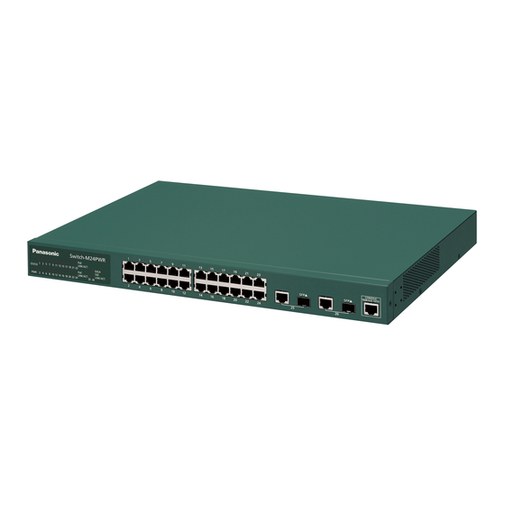
Switch-M24PWR is an Ethernet Switching Hub with management function having 24 ports of 10/100BASE-TX and two pairs of 10/100/1000BASE-T port and SFP extension slot, one of which is selectable. Ports 1 to 24 support IEEE802.3af compatible PoE power supply function. -
Page 12: Accessories
Please be sure to confirm the content. Please contact our distributor if any of the contents are insufficient. Quantity Installation Guide…………………………………………………………………… 1 CD-ROM (PDF version of Operating Instuctions)…………………..… 1 Mounting bracket (for 19-inch rack)………………………………………. 2 Screws (for 19-inch rack)……………………………………………………. 4 ... -
Page 13: Part Names And Functions
Power cord hook block Back panel Ground terminal Power port 10/100BASE-TX port SFP extension slot Front panel 10/100/1000BASE-T port RJ45 console port Fig. 1-1 Switch-M24PWR Fig. 1-2 Front LED Magnified View... -
Page 14: Led Behavior
Upon turning this Switching Hub on, all LEDs (PWR, STATUS, PoE and LINK/ACT for each port) light up. Then, the hardware self diagnosis is executed. Upon finishing the diagnosis, PWR and STATUS LEDs light in solid green. The Switching Hub is working as a Switching Hub. ... -
Page 15: Installation
Switch-M24PWR can be installed in a 19-inch rack. Mounting brackets and screws are included in the package, requiring no separate purchase. Two mounting brackets and eight screws (for fixing the main unit and the mounting bracket) are included in the package. Each side of the main unit has four screw holes. -
Page 16: Connection
Connection Cable Use a CAT5-compliant straight cable (twisted pair) with 8P8C RJ45 modular plugs. Network Configuration 100m or shorter 100m or 100m or Fig. 3-1 Connection example The length of the cable connecting this Switching Hub and a device must be 100 m or shorter. -
Page 17: Connecting An Sfp Extension Port
1000BASE-SX: 500 m or shorter/1000BASE-LX: 10 km or shorter 100m or 100m or shorter shorter Fig. 3-2 Optical fiber cable connection example Plugging an SFP module (optional) into an SFP extension port enables a optical fiber connection. The SFP extension port shares the port with the twisted pair port. -
Page 18: Connecting To Power
Connect the supplied power cord to the power port of this Switching Hub and connect the other end into an electric outlet. This Switching Hub operate at AC 100 to 240 V (50/60 Hz). This Switching Hub does not have a power ON/OFF switch. -
Page 19: Configuration
Upon power ON, this Switching Hub starts working as a Switching Hub. To use the SNMP functions and other functions, you need to configure the Switching Hub by using the console or Telnet. In this chapter, the configuration of this Switching Hub is explained in detail. -
Page 20: Login
Upon connecting, a login window, similar to Fig. 4-2-1, is displayed. If no similar window is displayed, make sure the transmission mode of console is correct or hit the enter key. ============================================================================= PN23249K/PN23249A Local Management System Version 2.0.0.xx MAC Address: 00:C0:8F:xx:xx:xx ============================================================================== Login Menu Login:... - Page 21 If you access the Switching Hub via Telnet, the screen displays "Remote Management System" on the top, similar to Fig. 4-2-2. ============================================================================= PN23249K/PN23249A Remote Management System Version 2.0.0.xx MAC Address: 00:C0:8F:xx:xx:xx ============================================================================== Login Menu Login: Fig. 4-2-2 Login screen (Telnet)
- Page 22 On the login screen, similar to Fig. 4-2-1 or Fig. 4-2-2, enter the login name. The Switching Hub's default login name is set to "manager." Enter "manager" and press the Return key. Then, you need to enter a password, as Fig. 4-2-3 displays. The Switching Hub's default password is the same as the login name ("manager").
-
Page 23: Basic Operations On The Screen
The console screen of the Switching Hub is organized as follows: Previous menu 1. Title Current menu PN23249K/PN23249A Local Management System Basic Switch Configuration -> System Admin. Configuration Menu Description: Switch-M24PWR Object ID: 1.3.6.1.4.1.396.5.4.1.19 4. Configuration Name: Location: Contact: -------------------------------- <COMMAND> -----------------------------------... - Page 24 command. If you enter a command or setting not available, an error message is shown in the explanation field.
-
Page 25: Main Menu
After the login process, the main menu, similar to Fig. 4-4-1, appears. This Switching Hub has a main menu and multiple sub-menus. These menus has a tree structure, with the main menu as its root. To move to a sub-menu, enter a command letter. -
Page 27: General Information Menu
On the Main Menu, pressing "G" opens the General Information Menu, as shown in Fig. 4-5-1. This screen displays this Switching Hub's basic information. You cannot edit shown information on this screen. PN23249K/PN23249A Local Management System Main Menu -> General Information System up for: 000day(s), 00hr(s), 00min(s), 00sec(s) Boot / Runtime Code Version: 1.0.0.xx / 2.0.0.xx... - Page 28 Screen Description System up for Displays the cumulative time since the power on of this Switching Hub. Boot / Displays this Switching Hub's firmware version. Runtime Code The left side displays the Boot Code and the right side displays the Version Runtime Code.
-
Page 29: Basic Switch Configuration
On the Main Menu, pressing "B" opens the Basic Switch Configuration Menu, as shown in Fig. 4-6-1. On this screen, you can configure basic configuration settings, such as IP address, SNMP, and ports. PN23249K/PN23249A Local Management System Main Menu -> Basic Switch Configuration Menu System [A]dministration Configuration System [I]P Configuration S[N]MP Configuration... -
Page 30: System Administration Configuration
On the Basic Switch Configuration Menu, pressing "A" opens the System Administration Configuration Menu, as shown in Fig. 4-6-2. On this screen, you can set administrative information, such as device name. PN23249K/PN23249A Local Management System Basic Switch Configuration -> System Admin. Configuration Menu Description: Switch-M24PWR Object ID: 1.3.6.1.4.1.396.5.4.1.19 Name: Location: Contact: -------------------------------- <COMMAND>... -
Page 31: System Ip Address Configuration
On the Basic Switch Configuration Menu, pressing "I" opens the System IP Configuration Menu, as shown in Fig. 4-6-3. On this screen, you can set IP-address-related settings for this Switching Hub. PN23249K/PN23249A Local Management System Basic Switch Configuration -> System IP Configuration Menu MAC Address: 00:C0:8F:xx:xx:xx IP Address:... - Page 33 Available commands are listed below. Set/edit the IP address. Press "I." The command prompt changes to "Enter IP address>." Enter an IP address for the Switching Hub. M Set/edit the subnet mask. Press "M." The command prompt changes to "Enter subnet mask>." Enter a subnet mask for the Switching Hub.
-
Page 34: Snmp Configuration
On the Basic Switch Configuration Menu, pressing "N" opens the SNMP Configuration Menu, as shown in Fig. 4-6-4. On this screen, you can configure the SNMP agent settings. PN23249K/PN23249A Local Management System Basic Switch Configuration -> SNMP Configuration Menu SNMP [M]anagement Configuration SNMP [T]rap Receiver Configuration [Q]uit to previous menu Command>... -
Page 35: Snmp Management Configuration
4.6.3.a SNMP Management Configuration On the SNMP Configuration Menu, pressing "M" opens the SNMP Management Configuration Menu, as shown in Fig. 4-6-5. On this screen, you can configure the SNMP manager settings. PN23249K/PN23249A Local Management System SNMP Configuration -> SNMP Management Configuration Menu SNMP Manager List: Status Privilege... - Page 36 Available commands are listed below. Set the SNMP manager status. Press "S." The command prompt changes to "Enter manager entry number>." Enter an SNMP manager entry number you wish to configure. Then, the command prompt changes to "Enable or Disable SNMP manger (E/D)>." Press "E" to enable the SNMP manager.
-
Page 37: Snmp Trap Receiver Configuration
4.6.3.b. SNMP Trap Receiver Configuration On the SNMP Configuration Menu screen, pressing "T" opens the SNMP Trap Receiver Configuration Menu screen, as shown in Fig. 4-6-6. On this screen, you can set the SNMP Trap sending settings. PN23249K/PN23249A Local Management System SNMP Configuration ->... - Page 38 Available commands are listed below. Enable/disable the trap receiver. Press "S." The command prompt changes to "Enter manager entry number>." Enter an entry number for the trap receiver you wish to configure. Then, the command prompt changes to "Enable or Disable Trap Receiver (E/D)>." Press "E" to enable the SNMP manager.
-
Page 39: Enable/Disable Individual Trap
4.6.3.c Enable/Disable Individual Trap On the SNMP Trap Receiver Configuration Menu screen, pressing "D" opens the Enable/Disable Individual Trap Menu screen, as shown in Fig. 4-6-7. On this screen, you can set the trap sending settings. PN23249K/PN23249A Local Management System SNMP Trap Receiver Configuration ->... - Page 40 Available commands are listed below. Enable/disable the trap sending when the link status changes. Press "A." The command prompt changes to "Enable or Disable SNMP Authentication trap (E/D)>." Press "E" to enable the trap sending. Press "D" to disable it. Add a port to which the trap is sent when its link status changes.
-
Page 41: Port Configuration Basic
On the Basic Switch Configuration Menu, pressing "p" opens the Port Configuration Basic Menu, as shown in Fig. 4-6-8. On this screen, you can configure port status display settings and port settings. PN23249K/PN23249A Local Management System Basic Switch Configuration -> Port Configuration Basic Menu Port Trunk Type Admin... - Page 42 Screen Description Port Displays the port number. Trunk Displays the group number for a trunked port. Type Displays the port type. 100TX The port type is 10/100BASE-TX. 1000T The port type is 10/100/1000BASE-T. 1000X The port type is SFP port. Admin Displays the current port status.
- Page 43 Available commands are listed below. Show the next page. Press "N." The screen displays the next port. Show the previous page. Pressing "P" displays the previous port. Enable/disable a port. Press "A." The command prompt changes to "Select port number to be changed>." Enter a port number you wish to configure.
-
Page 44: Port Configuration Extend
On the Basic Switch Configuration Menu, pressing "e" opens the Port Configuration Extend Menu, as shown in Fig. 4-6-9. On this screen, you can configure port status display settings and port settings. PN23249K/PN23249A Local Management System Basic Switch Configuration -> Port Configuration Extend Menu Port Trunk Type Link... - Page 46 Available commands are listed below. Show the next page. Press "N." The screen displays the next port. Show the previous page. Pressing "P" displays previous port. A name can be assigned to each port. Press "A." The command prompt changes to "Select port number to be changed>." Enter a port number you wish to configure.
-
Page 47: System Security Configuration
On the Basic Switch Configuration Menu, pressing "S" opens the System Security Configuration Menu, as shown in Fig. 4-6-10. On this screen, you can configure the various settings for accessing this Switching Hub for configuration and management. PN23249K/PN23249A Local Management System Basic Switch Configuration ->... - Page 48 Disabled: Access is disabled. IP Setup Displays the access settings for the IP address configuration software, Interface: bundled with the Panasonic network cameras. 'Enabled' is the factory default setting. * For instructions, refer to Appendix C. Enabled: Access is enabled.
- Page 49 Available commands are listed below. Configure the idle timeout settings for automatically terminating a console-connected session if no input is made. Press "C." The command prompt changes to "Enter console idle timeout>." Enter a value from 0 to 60 (minutes). Entering "0" disables the automatic termination. Configure the idle timeout settings for automatically terminating a Telnet-connected session if no input is made.
-
Page 50: Telnet Access Limitation Configuration
4.6.6.a. Telnet Access Limitation Configuration On the System Security Configuration Menu, pressing "A" opens the Telnet Access Limitation screen, as shown in Fig. 4-6-11. In this screen, you can configure limitation of equipment accessing to this Switching Hub via Telnet. PN23249K/PN23249A Local Management System System Security Configuration ->... - Page 51 Available commands are listed below. Set Enable/Disable of access limitation via Telnet. Set access limitation from Telnet to Enable. Set access limitation from Telnet to Disable. Set an IP address to be permitted. Five ranges can be set up. Press "A." The command prompt changes to "Enter IP address entry number>." Enter an IP address entry number between 1 and 5.
-
Page 52: Radius Configuration
4.6.6.b. RADIUS Configuration On the System Security Configuration Menu, pressing "R" opens the RADIUS Configuration Page screen, as shown in Fig. 4-6-12. In this screen, you can configure accessing to RADIUS server that is used in 802.1x port base authentication. PN23249K/PN23249A Local Management System System Security Configuration ->... - Page 53 Available commands are listed below. Set the NAS ID (NAS Identifier). Press "I." The command prompt changes to "Enter NAS ID>." Enter NAS ID in 16 characters or less. Set an IP address of RADIUS server. Press "A." The command prompt changes to "Enter IP Address for RADIUS server>." Enter an IP address.
-
Page 54: Syslog Transmission Configuration
4.6.6.c. Syslog Transmission Configuration On the System Security Configuration Menu, pressing "G" opens the Syslog Transmission Configuration Page screen, as shown in Fig. 4-6-13. In this screen, you can set Syslog server information to send a system log. PN23249K/PN23249A Local Management System System Security Configuration ->... - Page 55 Available commands are listed below. Set a status of Syslog Transmission. Press "S." The command prompt changes to "Enter manager entry number>." Enter No. you wish to set. Then, the command prompt changes to "Enable or Disable Server (E/D)>." Enter "E" to enable, or "D" to disable the server. Set Facility.
-
Page 56: Mail Report Configuration
On the Basic Switch Configuration Menu, pressing "M" opens the Mail Report Configuration Menu screen, as shown in Fig. 4-6-14. In this screen, you can set notification function of failures or operation information using E-mail. Currently, the E-mail contents are supported Japanese only. PN23249K/PN23249A Local Management System Basic Switch Configuration ->... - Page 57 Available commands are listed below. Set an address of SMTP server. Press "S." The command prompt changes to "Enter new SMTP server>." Enter an address you wish to set. Set a mail address of destination. Press "D." The command prompt changes to "Enter destination account entry number>."...
-
Page 58: Report Data Configuration
4.6.7.a. Report Data Configuration On the Mail Report Configuration Menu, pressing "C" opens the Report Data Configuration screen, as shown in Fig. 4-6-15. In this screen, you can set content to be described in a report. PN23249K/PN23249A Local Management System Mail Report Configuration Menu ->... - Page 59 Collisions Indicates whether the number of collisions is set as an object of notification or not. Errors Indicates whether the number of errors is set as an object of notification or not.
- Page 60 Available commands are listed below. Set a reporting interval. Press "R." The command prompt changes to "Set report interval to daily/weekly/monthly (D/W/M)>." Enter "D" when notifying every day, or "W" when notifying every week, or "M" when notifying every month, respectively. Set an interval to obtain samples.
-
Page 61: Forwarding Database
On the Basic Switch Configuration Menu, pressing "F" opens the Forwarding Database Information Menu screen, as shown in Fig. 4-6-16. In this screen, a list of MAC address required for transferring packets that have been learned and recorded. It is possible to add or delete MAC address statically. PN23249K/PN23249A Local Management System Basic Switch Configuration ->... -
Page 62: Adding Or Deleting Mac Address
4.6.8.a. Adding or deleting MAC address On the Forwarding Database Information Menu, pressing "S" opens the Static Address Table Menu screen, as shown in Fig. 4-6-17. In this screen, you can add or delete MAC address statically . PN23249K/PN23249A Local Management System Forwarding Database Menu ->... -
Page 63: Setting Learning Mode Of Mac Address
4.6.8.b. Setting learning mode of MAC address On the Forwarding Database Information Menu, pressing "A" opens the MAC Learning Menu screen, as shown in Fig. 4-6-18. In this screen, you can set a learning mode of MAC address by port. PN23249K/PN23249A Local Management System Forwarding Database Menu ->... -
Page 64: Displaying Mac Address Table By Port
4.6.8.c Displaying MAC address table by port On the Forwarding Database Information Menu, press "P." The command prompt changes to "Enter Port Number>." Specifying a port number opens the Display MAC Address by Port screen as shown in Fig. 4-6-19. In this PN23249K/PN23249A Local Management System Forwarding Database Menu ->... -
Page 66: Displaying All Mac Addresses
4.6.8.d Displaying all MAC addresses On the Forwarding Database Information Menu, pressing "M" opens the Display MAC Address by MAC screen, as shown in Fig. 4-6-20. In this screen, you can display all the MAC address tables in this Switching Hub. PN23249K/PN23249A Local Management System Forwarding Database Menu ->... -
Page 67: Displaying Mac Address Table By Vlan
4.6.8.e Displaying MAC address table by VLAN On the Forwarding Database Information Menu, press "V." The command prompt changes to "Enter VLAN ID>." Specifying a port number opens the Display MAC Address by VLAN ID screen as shown in Fig. 4-6-21. In this screen, you can display MAC Address table by VLAN. - Page 68 Press "S." The command prompt changes to "Enter VLAN ID>." Enter VLAN ID you wish to display. Return to the previous menu.
-
Page 69: Time Configuration
In this Switching Hub, it is possible to set the exact time by synchronizing the internal clock to an external SNTP server's clock via SNTP (Simple Network Time Protocol). On the Basic Switch Configuration Menu, pressing "T" opens the Time Configuration Menu screen, as shown in Fig. - Page 70 Screen Description Time (HH:MM:SS): Displays time of internal clock. Date Displays date of internal clock. (YYYY/MM/DD): SNTP Server IP Displays an IP address of SNTP server that executes time synchronization. SNTP Polling Interval Displays an interval of time synchronization with SNTP server. Time Zone: Displays time zone.
-
Page 71: Arp Table Configuration
On the Basic Switch Configuration Menu, pressing "R" opens the ARP Table screen, as shown in Fig. 4-6-23. In this screen, you can refer and configure ARP table. PN23249K/PN23249A Local Management System Basic Switch Configuration -> ARP Table Sorting Method : By IP ARP Age Timeout : 7200 seconds IP Address... - Page 72 Available commands are listed below. Display the next page. Press "N" to display the next page. Display the previous page. Press "P" to display the previous page. Set an age-out time of ARP table. Press "T." The command prompt changes to "Enter ARP age timeout value >." Enter Age-out time of ARP table with a value of 30 to 86400 (sec.).
-
Page 73: Advanced Switch Configuration
Selecting "A" from Main Menu opens the Advanced Switch Configuration Menu screen, as shown in Fig. 4-7-1. In this screen, you can configure the settings of VLAN, Link aggregation, Port monitoring, Spanning tree, Access control, QoS, Storm control, IEEE802.1X authentication function, IGMP PN23249K/PN23249A Local Management System Main Menu ->... - Page 74 Quit to previous menu Quits the Advanced Switch Configuration Menu and returns to the Main menu.
-
Page 75: Vlan Management
4.7.1.a. Special Features Corresponding to IEEE802.1Q Tag VLAN, it is possible to send frames attaching a VLAN tag (hereinafter, called as just "tag"). Having two different parameters of VLAN ID and PVID, destination of transferring untagged frames is determined by a combination of these parameters. -
Page 76: Vlan Management Menu
4.7.1.b. VLAN Management Menu On the Advanced Switch Configuration Menu, pressing "V" opens the VLAN Management Menu screen, as shown in Fig. 4-7-2. In this screen, you can configure VLAN-related settings. PN23249K/PN23249A Local Management System Advanced Switch Configuration -> VLAN Management Menu GVRP Status : Disabled Total VLANs : 4... - Page 77 setting, and the management VLAN status of VLAN ID=1 is UP.
- Page 78 Available commands are listed below. Display the next page. Press "N" to display the next page. Display the previous page. Press "P" to display the previous page. Create new VLAN. Pressing "C" opens the "VLAN Create Menu" screen. For details, refer to the section (4.7.1.c).
- Page 79 Note: When Internet Mansion mode is enabled, there are constrained conditions as the followings. Please use the device after confirming these constrained conditions. (1) Combined usage with Spanning Tree function is not possible. (2) Combined usage with IGMP Snooping function is not possible. (3) Combined usage with Link Aggregation function is not possible.
-
Page 80: Vlan Creation Menu
4.7.1.c. VLAN Creation Menu On the VLAN Management Menu, pressing "C" command opens the VLAN Creation Menu screen, as shown in Fig. 4-7-3. In this screen, you can PN23249K/PN23249A Local Management System VLAN Management -> VLAN Creation Menu VLAN ID VLAN Name Port Members Dynamic Ports :... - Page 81 Available commands are listed below. Set the VLAN ID (VLAN Identifier). Press "S." The command prompt changes to "Set VLAN ID->Enter VLAN ID>." Enter new VLAN ID. Set a name of VLAN. Press "N." The command prompt changes to "Set VLAN name->Enter VLAN name>." Enter new VLAN name in 30 characters or less.
-
Page 82: Vlan Modification Menu
4.7.1.d. VLAN Modification Menu On the VLAN Management Menu, pressing "o" command and specifying VLAN ID of object opens the VLAN Modification Menu screen, as shown in Fig. 4-7-4. In this screen, you can modify VLAN-related setting information. PN23249K/PN23249A Local Management System VLAN Management ->... - Page 83 Available commands are listed below. Set a name of VLAN. Press "N." The command prompt changes to "Set VLAN name->Enter VLAN name>." Enter new VLAN name in 30 characters or less. Set a member of VLAN. Press "P." The command prompt changes to "Enter egress port number>." Enter a port number you wish to set.
-
Page 84: Vlan Port Configuration Menu
4.7.1.e. VLAN Port Configuration Menu On the VLAN Management Menu, pressing "S" command opens the VLAN Port Configuration Menu screen, as shown in Fig. 4-7-5. In this screen, you can configure VLAN-related settings by port. PN23249K/PN23249A Local Management System VLAN Management -> VLAN Port Configuration Menu Port PVID Acceptable Frame Type GVRP ---- ---- --------------------- --------... - Page 85 Available commands are listed below. Display the next page. Press "N" to display the next page. Display the previous page. Press "P" to display the previous page. Configure PVID settings. Press "V." The command prompt changes to "Enter port number>." Enter a port number you wish to configure.
-
Page 86: Link Aggregation
4.7.2.a About Link aggregation Link aggregation is a function that is possible to increase bandwidth between switches grouping multiple Switching ports connecting the grouped ports each other. Using this Link Aggregation function is called as trunking. This Switching Hub supports the LACP (Link Aggregation Control Protocol) specified in IEEE802.3ad. - Page 87 Fig. 4-7-6 displays an example in which two ports of 1000BASE-T were grouped in one and between switches was connected with 2000 Mbps (one-way 1000 Mbps x 2). One-way 1000 Mbps × 2 = 2000 Mbps Fig. 4-7-6 Configuration example 1 using trunking Fig.
-
Page 88: Trunk Configuration
4.7.2.b. Trunk Configuration On the Advanced Switch Configuration Menu, pressing "L" opens the Trunk Configuration Menu screen, as shown in Fig. 4-7-8. In this screen, you can configure trunking. PN23249K/PN23249A Local Management System Advanced Switch Configuration -> Trunk Configuration Menu System Priority : 1 Mode Member Port List... - Page 89 Note: If each Switching Hub uses LACP passive mode, LACP negotiation is not executed then the packet storm may be occurred. When constructing trunking using LACP, make sure to configure one side to be Active.
- Page 90 Available commands are listed below. Display the next page. Press "N" to display the next page. Display the previous page. Press "P" to display the previous page. Set System Priority value of this Switching Hub in LACP. Press "T." The command prompt changes to "Enter system priority for LACP >." Configure new trunking settings.
-
Page 91: Set Port Priority For Lacp
4.7.2.c. Set Port Priority for LACP On the Trunk Configuration Menu, pressing "o" opens the Set Port Priority screen, as shown in Fig. 4-7-9. In this screen, you can set priority value of PN23249K/PN23249A Local Management System Trunk Configuration Menu -> Set Port Priority System Priority : System ID 00:C0:8F:xx:xx:xx... - Page 92 Press "S." Return to the previous menu.
-
Page 93: Lacp Group Status
4.7.2.d. LACP Group Status On the Trunk Configuration Menu, pressing "G" command and specifying Key that has become LACP group open the LACP Group Status screen, as shown in Fig. 4-7-10. In this screen, you can confirm the status of LACP group. - Page 95 Available commands are listed below. Display the next page. Press "N" to display the next page. Display the previous page. Press "P" to display the previous page. Return to the previous menu.
-
Page 96: Port Monitoring Configuration
On the Advanced Switch Configuration Menu, pressing "M" opens the Port Monitoring Configuration Menu screen, as shown in Fig. 4-7-11. In this Switching Hub, when analyzing communication using a protocol analyzer, etc., it is possible to monitor other port's packet that is hidden under normal conditions because of being filtered. - Page 97 Available commands are listed below. Set a port to be monitored (port to which analyzer, etc. is connected). Press "S." The command prompt changes to "Enter port number>." Enter a port number you wish to configure. M Configure a port to be monitored. Press "M."...
-
Page 98: Multiple Spanning Tree Configuration
On the Advanced Switch Configuration Menu, pressing "S" opens the Multiple Spanning Tree Configuration screen, as shown in Fig. 4-7-12. This Switching Hub supports the following three modes: IEEE802.1s Multiple Spanning Tree Protocol (MSTP: Fig. 4-7-13), IEEE802.1w compatible Rapid Spanning Tree Protocol (RSTP: Fig. 4-7-14), and IEEE802.1D compatible Spanning Tree Protocol (STP: Fig. - Page 99 PN23249K/PN23249A Local Management System Advanced Switch Configuration -> Multiple Spanning Tree Configuration Global MSTP Status: Disabled Protocol Version : MSTP MST Configuration Name MST Revision Level MST Config Digest : 00000000000000000000000000000000 -------------------------------- <COMMAND> ----------------------------------- [E]nable/Disable Global MSTP CIST [B]asic Port Configuration Set MSTP Protocol [V]ersion CIST [A]dvanced Port Configuration Set MSTI Configuration [N]ame...
- Page 100 PN23249K/PN23249A Local Management System Advanced Switch Configuration -> Multiple Spanning Tree Configuration Global MSTP Status: Disabled Protocol Version : STP-Compatible MST Configuration Name MST Revision Level MST Config Digest : 00000000000000000000000000000000 -------------------------------- <COMMAND> ----------------------------------- [E]nable/Disable Global MSTP CIST [B]asic Port Configuration Set MSTP Protocol [V]ersion CIST [A]dvanced Port Configuration Set MSTI Configuration [N]ame...
- Page 101 Available commands are listed below. Configure ON/OFF of Spanning Tree Protocol. Press "E." The command prompt changes to "Enable or Disable STP (E/D)>." Enter "E" if you wish to use, or "D" if you don't wish to use, respectively. Configure an operation mode of Spanning Tree Protocol. Press "V."...
-
Page 102: Cist (Mst Instance 0) Configuration
4.7.4.a. CIST (MST Instance 0) Configuration On the Multiple Spanning Tree Configuration, pressing "C" opens the CIST Configuration screen, as shown in Fig. 4-7-16. On this screen, you can do CIST configuration. PN23249K/PN23249A Local Management System Multiple Spanning Tree Configuration -> CIST Configuration CIST Root Port: Time Since Topology Change: 0 Sec. - Page 103 Screen Description CIST Root Port: Displays the present root port. CIST Root Path Displays a cost from the root port to root bridge. Cost: CIST Root: Displays bridge ID of a root bridge. CIST Regional Displays a path cost to a regional root bridge (root bridge of CIST Root Cost: tree in the MST region).
-
Page 104: Cist Basic Port Configuration
4.7.4.b CIST Basic Port Configuration On the Multiple Spanning Tree Configuration, pressing "B" opens the CIST Basic Port Configuration screen, as shown in Fig. 4-7-17. On this screen, you can do CIST basic configuration for each port. PN23249K/PN23249A Local Management System Multiple Spanning Tree Configuration ->... - Page 105 Screen Description BPDU Guard Displays enable/disable of auto-recovery of BPDU guard. Recovery The factory default setting is Disabled. Enabled Auto-recovery is enabled Disabled Auto-recovery is disabled BPDU Guard Displays the time to auto-recovery. The factory default setting is 300 sec. Recovery Timer Port...
- Page 106 Available commands are listed below. Display the next page. Press "N" to change the display to the next page. Display the previous page. Press "P" to change the display to the previous page. For setting priority of each port in the Switching Hub Press "I"...
-
Page 107: Cist Advanced Port Configuration
4.7.4.c. CIST Advanced Port Configuration On the Multiple Spanning Tree Configuration, pressing "A" opens the CIST Advanced Port Configuration screen, as shown in Fig. 4-7-18. On this screen, you can do advanced configuration on CIST for each port. PN23249K/PN23249A Local Management System Multiple Spanning Tree Configuration ->... - Page 108 Screen Description Port Displays the port number. Trunk Displays the group number (key) of the trunk if trunking is set. Link Displays the state of link. Link is established normally. DOWN Link is not established. State Displays the present state of port. Forwarding Displays the state of normal communications based on the calculation result.
- Page 109 Available commands are listed below. Display the next page. Press "N" to change the display to the next page. Display the previous page. Press "P" to change the display to the previous page. Set Edge Status of each port. Press "E" to change the command prompt to "Select port number to be changed>." Enter a port number.
-
Page 110: Mst Instance Configuration
4.7.4.d. MST Instance Configuration On the Multiple Spanning Tree Configuration, pressing "T" opens the MSTP Instance Configuration screen, as shown in Fig. 4-7-19. On this screen, you can do instances configuration on the spanning tree. PN23249K/PN23249A Local Management System Multiple Spanning Tree Configuration -> MSTP Instance Configuration Instance VLANs Mapped -------- --------------------------------------------------------------------- -------------------------------- <COMMAND>... - Page 111 Available commands are listed below. Display the next page. Press "N" to change the display to the next page. Display the previous page. Press "P" to change the display to the previous page. Add VLAN ID to be associated to MST instance. Press "A"...
-
Page 112: Mst Instance Advanced Configuration
4.7.4.e. MST Instance Advanced Configuration On the MSTP Instance Configuration, pressing "M" and entering MST instance ID open the MST Instance Configuration screen, as shown in Fig. 4-7-20. On this screen, you can do advanced configuration of MST instance. PN23249K/PN23249A Local Management System MST Instance Configuration ->... - Page 113 Press "I" to change the command prompt to "Enter MSTI Priority>." Enter a value for bridge priority. Return to the previous menu.
-
Page 114: Mst Instance Port Configuration
4.7.4.f. MST Instance Port Configuration On the MSTP Instance Configuration, pressing "C" and entering MST instance ID open the MST Instance Port Configuration screen, as shown in Fig. 4-7-21. On this screen, you can do MST Instance Port Configuration. PN23249K/PN23249A Local Management System MSTP Instance Configuration ->... - Page 115 Screen Description Displays selected MST instance ID. Instance: Port Displays the port number. Trunk Displays the group number (key) of the trunk if trunking is set. Link Displays the state of link. Link is established normally. DOWN Link is not established. State Displays the current state of port.
- Page 116 Press "S" to change the command prompt to "Select port number to be changed>." Enter a port number. Then, "Enable or Disable STP for port # (E/D)>" is displayed. If the spanning tree is used, press "E." If not, press "D." Return to the previous menu.
-
Page 117: Mst Instance Topology Information
4.7.4.g MST Instance Topology Information On the MSTP Instance Configuration, pressing "I" and entering MST instance ID open the MST Instance Topology Information screen, as shown in Fig. 4-7-22. On this screen, you can do setting MST Instance Topology Information. PN23249K/PN23249A Local Management System MSTP Instance Configuration ->... - Page 118 Return to the previous menu.
-
Page 119: Designated Topology Information
4.7.4.h. Designated Topology Information On the Multiple Spanning Tree Configuration Menu, pressing "I" opens the Designated Topology information screen, as shown in Fig. 4-7-23. This screen displays configuration information of the spanning tree for each port. PN23249K/PN23249A Local Management System Multiple Spanning Tree Configuration ->... -
Page 120: Regional Topology Information
4.7.4.i. Regional Topology Information On the Multiple Spanning Tree Configuration Menu, pressing "g" opens the Regional Topology Information screen, as shown in Fig. 4-7-24. This screen displays configuration information of the spanning tree for each port. PN23249K/PN23249A Local Management System Multiple Spanning Tree Configuration ->... -
Page 122: Access Control Configuration Menu
On the Advanced Switch Configuration Menu, pressing "A" opens the Access Control Configuration Menu, as shown in Fig. 4-7-25. On this screen, you can set Access Control. PN23249K/PN23249A Local Management System Advanced Switch Configuration Menu -> Access Control Configuration Menu [C]lassifier [I]n-Profile Action [O]ut-Profile Action... -
Page 123: Classifier Configuration Menu
4.7.5.a. Classifier Configuration Menu On the Access Control Configuration Menu, pressing "C" opens the Classifier Configuration Menu, as shown in Fig. 4-7-26. On this screen, you can set classifier. PN23249K/PN23249A Local Management System Access Control Configuration -> Classifier Configuration Menu Multifield Classifier: Total Entries : 1 Index Src IP Addr/Mask... - Page 124 Available commands are listed below. Display the next page. Press "N" to change the display to the next page. Display the previous page. Press "P" to change the display to the previous page. Create a new classifier. Press "C" to change the screen to the Create Classifier Configuration Menu. For the Create Classifier Configuration Menu, see the next section of 4.7.5.b.
-
Page 125: Create Classifier Configuration Menu
4.7.5.b. Create Classifier Configuration Menu On the Classifier Configuration Menu, pressing "C" opens the Create Classifier Configuration Menu, as shown in Fig. 4-7-27. On this screen, you can create a classifier. PN23249K/PN23249A Local Management System Classifier Configuration -> Create Classifier Configuration Menu Classifier Index Source MAC Address Source MAC Mask Length... - Page 126 ICMP Type Displays the ICMP type.
- Page 127 Available commands are listed below. Set a classifier index. Press "C" to change the command prompt to "Enter Classifier Index>." Enter a classifier index from 1 to 65535. Set a source MAC address to be filtered. Press "S" to change the command prompt to "Enter source MAC address>." Enter the sender MAC address, such as xx:xx:xx:xx:xx:xx.
- Page 128 M Set ICMP type to be filtered. (* Protocol needs to be set to ICMP.) Press "M" to change the command prompt to "Enter ICMP type>." Enter ICMP type in a range from 0 to 18. Set TCP SYN Flag to be filtered. (* Protocol needs to be set to TCP.) Press "Y"...
-
Page 129: Classifier Configuration Menu
4.7.5.c. Classifier Configuration Menu On the Classifier Configuration Menu, pressing "M" opens the More Classifier Information screen, as shown in Fig. 4-7-28 and Fig. 4-7-29. On this screen, you can refer to classifier information. PN23249K/PN23249A Local Management System Access Control Configuration -> Classifier Configuration Menu Multifield Classifier: Total Entries : 1 Index Source MAC Addr./ Mask... - Page 130 Screen Description Total Entries Displays the number of the created Classifiers. Classifier Index Displays a classifier index. Source MAC Address Displays source MAC address. Destination MAC Displays destination MAC address. Address 802.1p Priority Displays priority of IEEE802.1p. VLAN ID Displays VLAN ID. TCP SYN Flag Displays TCP SYN flag.
-
Page 131: Show Detailed Entries Information Menu
4.7.5.d. Show Detailed Entries Information Menu On the Classifier Configuration Menu, pressing "S" opens the Show Detailed Entries Information Menu, as shown in Fig. 4-7-30. On this screen, you can refer to detailed Classifier information. Classifier needs to be created in order to refer to. - Page 132 802.1p Priority Displays priority of IEEE802.1p. TCP SYN Flag Displays the TCP SYN flag. ICMP Type Displays ICMP type.
-
Page 133: In-Profile Action Configuration Menu
4.7.5.e. In-Profile Action Configuration Menu On the Access Control Configuration Menu, pressing "I" opens the In-profile Action Configuration Menu, as shown in Fig. 4-7-31. On this screen, you can set In-Profile. PN23249K/PN23249A Local Management System Access Control Configuration -> In-Profile Action Configuration Menu In-Profile Action: Total Entries : 0 Index Deny/Permit Policed-DSCP... - Page 134 Available commands are listed below. Display the next page. Press "N" to change the display to the next page. Display the previous page. Press "P" to change the display to the previous page. Create In-profile. Press "C." The screen changes to the Create In-Profile Action Menu. See 4.7.5.f. Delete In-profile.
-
Page 135: Create In-Profile Action Menu
4.7.5.f. Create In-Profile Action Menu On the In-Profile Action Configuration screen, pressing "C" opens the Create In-Profile Action Menu, as shown in Fig. 4-7-32. On this screen, you can create In-profile. PN23249K/PN23249A Local Management System In-Profile Action Configuration -> Create In-Profile Action Menu Index Deny/Permit : Permit... - Page 136 Available commands are listed below. Set the In-profile index number. Press "I" to change the command prompt to "Enter in-profile action index>." Enter 1 to 65535 for index number. Set deny/permit of packet. Press "D" to change the command prompt to "Select Deny/Permit (1-2)>." To deny, "1."...
-
Page 137: Out-Profile Action Configuration Menu
4.7.5.g. Out-Profile Action Configuration Menu On the Access Control Configuration Menu, pressing "O" opens the Out-Profile Action Configuration Menu, as shown in Fig. 4-7-33. On this screen, you can set Out-Profile. PN23249K/PN23249A Local Management System Access Control Configuration -> Out-Profile Action Configuration Menu Out-Profile Action: Total Entries : 0 Index... - Page 138 Available commands are listed below. Display the next page. Press "N" to change the display to the next page. Display the previous page. Press "P" to change the display to the previous page. Create Out-Profile. Press "C" to change the screen to the Create Out-Profile Action Menu. Refer to the section 4.7.5.h.
-
Page 139: Create Out-Profile Action Menu
4.7.5.h. Create Out-Profile Action Menu On the Out-Profile Action Configuration screen, pressing "C" opens the Create Out-Profile Action Menu, as shown in Fig. 4-7-34. On this screen, you can create Out-Profile. PN23249K/PN23249A Local Management System Out-Profile Action Configuration -> Create Out-Profile Action Menu Index Deny/Permit : Permit... - Page 140 Available commands are listed below. Set the Out-Profile index number. Press "I" to change the command prompt to "Enter Out-Profile action index>." Enter 1 to 65535 for index number. Set deny/permit of packet. Press "D" to change the command prompt to "Select Deny/Permit (1-2)>." To deny, select "1."...
-
Page 141: Port List Configuration Menu
4.7.5.i. Port List Configuration Menu On the Access Control Configuration Menu, pressing "L" opens the Port List Configuration Menu, as shown in Fig. 4-7-35. On this screen, you can set a port list to apply Access Control. PN23249K/PN23249A Local Management System Access Control Configuration ->... - Page 142 Available commands are listed below. Display the next page. Press "N" to change the display to the next page. Display the previous page. Press "P" to change the display to the previous page. Creates a port list. Press "C" to change the command prompt to "Enter port list index>." Enter an Index number to be executed.
-
Page 143: Policy Configuration Menu
4.7.5.j. Policy Configuration Menu On the Access Control Configuration Menu, pressing "P" opens the Policy Configuration Menu, as shown in Fig. 4-7-36. On this screen, you can set policy. PN23249K/PN23249A Local Management System Access Control Configuration -> Policy Configuration Menu Policy : Total Entries : 0 Index Classifier Seq. - Page 144 Available commands are listed below. Display the next page. Press "N" to change the display to the next page. Display the previous page. Press "P" to change the display to the previous page. Create Policy. Press "C" to change the screen to the Create Policy Configuration Menu. Refer to the section 4.7.5.k for the Create Policy Configuration.
-
Page 145: Create Policy Configuration Menu
4.7.5.k. Create Policy Configuration Menu On the Policy Configuration Menu, pressing "C" opens the Create Policy Configuration menu, as shown in Fig. 4-7-37. On this screen, you can create a policy. PN23249K/PN23249A Local Management System Policy Configuration -> Create Policy Configuration Menu Policy Index Classifier Index Policy Sequence... - Page 146 Available commands are listed below. Set a policy index number. Press "P" to change the command prompt to "Enter policy index>." Enter a policy index number. Set an index number of applicable classifier. Press "C" to change the command prompt to "Enter classifier index>." Enter an index number of applicable classifier.
-
Page 147: Quality Of Service Configuration
On the Advanced Switch Configuration Menu, pressing "S" opens the Quality of Service Configuration Menu, as shown in Fig. 4-7-38. QoS (Quality of Service) configuration of the Switching Hub is available. PN23249K/PN23249A Local Management System Advanced Switch Configuration Menu -> Quality of Service Configuration Menu [T]raffic Class Configuration [E]gress Rate Limiting [Q]uit to previous menu... -
Page 148: Traffic Class Configuration
4.7.6.a. Traffic Class Configuration On the Quality of Service Configuration Menu, pressing "T" opens the Traffic Class Configuration screen, as shown in Fig. 4-7-39. On this screen, you can set QoS in packets. PN23249K/PN23249A Local Management System Quality of Service Configuration -> Traffic Class Configuration Menu QoS Status: Disabled Priority Traffic Class... -
Page 149: Configuration Of Scheduling Method
4.7.6.b. Configuration of Scheduling Method On the Quality of Service Configuration Menu, pressing "C" opens the Scheduling Method screen, as shown in Fig. 4-7-40. On this screen, you can set a scheduling method. PN23249K/PN23249A Local Management System Quality of Service Configuration -> Scheduling Method Scheduling Method: Strict Traffic Class Weight... -
Page 150: Egress Rate Limiting Configuration Menu
On the Quality of Service Configuration Menu, pressing "C" opens the Egress Rate Limiting Configuration Menu, as shown in Fig. 4-7-41. On this screen, you can set bandwidth control. PN23249K/PN23249A Local Management System Quality of Service Configuration -> Egress Rate Limiting Configuration Menu Port Bandwidth Status... -
Page 151: Storm Control Configuration Menu
Press "S" to change the command prompt to "Enter port number e.g.: 1, 3, 5-26>." Enter a port number to designate. Then, the command prompt changes to "Enable or Disable Status (E/D)>." Press "E" to enable bandwidth control configuration, and press "D" to disable it. Return to the previous menu. - Page 152 Threshold: Displays the threshold of the number of packets per second.
- Page 153 Available commands are listed below. Enable/disable the unknown unicast storm control. Press "D." The command prompt changes to "Enter port number>." Enter a port number you wish to specify. Then, the command prompt changes to "Enable or Disable DLF storm control status (E/D)>." Press "E" to enable the unknown unicast storm control, and press "D"...
-
Page 154: Access Control Configuration
On the Advanced Switch Configuration Menu screen, pressing "x" opens the 802.1X Access Control Configuration screen as shown in Fig. 4-7-43. On this screen, you can configure the IEEE 802.1X access control. PN23249K/PN23249A Local Management System Advanced Switch Configuration -> 802.1X Access Control Configuration Menu [P]erUser/MAC Based Access Control Configuration [F]orce Authorized MAC Address Configuration [G]uest/Default VLAN Configuration... -
Page 155: Ieee 802.1X Port Based Access Control Configuration
4.7.9.a. IEEE 802.1X Port Based Access Control Configuration On the 802.1X Access Control Configuration Menu screen, pressing "p" opens the Port Based Access control Configuration Menu as shown in Fig. 4-7-44. On this screen, you can configure the IEEE 802.1X port based access control. - Page 156 Authorized Displays the MAC address of successfully authenticated supplicant or a MAC Address supplicant using Guest Access. If neither is used, this field displays "--:--:--:--:--:--."...
- Page 157 Operational Displays the operation status of controlled direction by IEEE 802.1X Control function. Direction Both Unless the client is authenticated, this Switching Hub does not send or receive packets from the port. Unless the client is authenticated, this Switching Hub does not receive packets from the port.
- Page 158 Available commands are listed below. Set Default VLAN ID. Press "F." The command prompt changes to "Enter default VLAN ID>." Enter an integer between 1 and 4094. Enter 0 to disable the Default VLAN function. Set the interval time to reattempt of authentication. Press "T."...
-
Page 159: Mac Based Access Control Configuration
4.7.9.b. MAC Based Access Control Configuration On the 802.1x Port Base Access Control Configuration screen, pressing "M" changes the command prompt to "Select the Port based or MAC based auth mode (P/M) >." Pressing "M" opens the MAC Based Access Control Configuration Menu as shown in Fig. - Page 160 Transmit Period The number of seconds to wait before requesting the RADIUS server to resend an authentication request The factory default setting is 30 seconds. Max Request The maximum number of times of retransmitting an authentication request. The factory default setting is 2 times. Supplicant Displays the timeout for the client.
- Page 161 Available commands are listed below. Show the next page. Press "N" to go to the next page. Show the previous page. Press "V" to go to the previous page. Set the number of terminals that can be authenticated by the port. Press "B."...
- Page 162 Initialize the authentication status. Press "Z." The command prompt changes to "Select the All MAC or MAC address (A/M) >." Press "A" to initialize all MAC addresses. Press "M" to initialize each MAC address individually. If you press "A," the command prompt changes to "Initialize all MAC (Y/N) >."...
-
Page 163: Force Authorized Mac Configuration Menu
4.7.9.c. Force Authorized MAC Configuration Menu On the 802.1x Access Control Configuration screen, pressing "F" opens the Force Authorized MAC Configuration Menu as shown in Fig. 4-7-46. On this screen, configure addresses terminals authorized/unauthorized without IEEE 802.1X authentication. PN23249K/PN23249A Local Management System 802.1x Access Control Configuration ->... - Page 164 Available commands are listed below. Show the next page. Press "N" to go to the next page. Show the previous page. Press "V" to go to the previous page. Add/delete a MAC address of a terminal to be authorized/unauthorized for access without authentication.
-
Page 165: Guest/Default Vlan Configuration Menu
4.7.9.d. Guest/Default VLAN Configuration Menu On the 802.1x Access Control Configuration screen, pressing "G" opens the Guest/Default VLAN Configuration Menu as shown in Fig. 4-7-47. On this screen, you can configure Guest Access and the default VLAN. Guest Access is a function to assign a terminal that failed authentication or a terminal that caused supplicant timeout to a specific VLAN. - Page 166 Available commands are listed below. Show the next page. Press "N" to go to the next page. Show the previous page. Press "V" to go to the previous page. Specify a VLAN to be assigned when a terminal that failed authentication or that does not have a supplicant is connected.
-
Page 167: Ieee 802.1X Statistics Menu
4.7.9.e. IEEE 802.1X Statistics Menu On the 802.1x Access Control Configuration screen, pressing "s" opens the Statistics Menu as shown in Fig. 4-7-48. On this screen, you can monitor the number of IEEE 802.1X packets as statistics information of the Switching Hub and thereby keep an eye on the network status. - Page 168 Available commands are listed below. Change the target port of the counter value display. Press "S." The command prompt changes to "Select Port number>." Enter the port number you wish to display. Show the values of the next port. Press "N." The screen displays the counter values of the next port. After you reach Port 26, you cannot go back to Port 1 by pressing "N."...
- Page 169 Fig. 4-7-49 Display of values accumulated after resetting the counters...
- Page 170 Screen Description Port Displays the port number. Refresh Displays the refresh interval. Elapsed Time Displays the time elapsed since resetting of the counters. Since Reset Counter Name Displays each counter name. Total Displays values accumulated in the counters. Available commands are listed below. Change the target port of the counter value display.
- Page 171 The counters are described below. TxReqId The number of EAP Request Identify frames sent by this Switching TxReq The number of EAP Request frames sent by this Switching Hub TxTotal The total number of all types of EAP frames sent by this Switching RxStart The number of EAPOL Start frames received from supplicants RxLogoff...
-
Page 172: Eap-Request Configuration Menu
4.7.9.f. EAP-Request Configuration Menu On the 802.1x Access Control Configuration screen, pressing "E" opens the EAP-Request Configuration Menu as shown in Fig. 4-7-50. On this screen, you can configure EAP Request sending in MAC-based access control mode. PN23249K/PN23249A Local Management System 802.1x Access Control Configuration ->... - Page 173 4.7.9.f.1. EAP-Request Port Configuration Menu On the EAP-Request Configuration screen, pressing "E" opens the EAP-Request Port Configuration Menu as shown in Fig. 4-7-51. On this screen, you can configure EAP Request sending for each port in MAC-based access control mode. PN23249K/PN23249A Local Management System 802.1x Access Control Configuration ->...
- Page 174 Press "S." The command prompt changes to "Enter port number>." Enter the port number for which you wish to change the setting. Then, the command prompt changes to "Enable or Disable EAP-Request ?(E/D) >." Press "E" to enable EAP-Request. Press "D" to disable it.
- Page 175 4.7.9.f.2. Unauthorized MAC Address Table Menu On the EAP-Request Configuration screen, pressing "U" opens the Unauthorized MAC Address Table Menu as shown in Fig. 4-7-52. This screen displays terminals that are unauthorized in MAC-based access control mode. (If you enable EAP Request sending in the manner described in 4.7.9.f.1, then the EAP Request is sent to the unauthorized MAC addresses shown on this screen.) PN23249K/PN23249A Local Management System...
- Page 176 Available commands are listed below. Show the next page. Press "N." The screen displays the next port. Show the previous page. Press "V." The screen displays the previous port. Set the time of saving unauthorized MAC addresses. Press "T." The command prompt changes to "Enter new age-out time>." Set the time in seconds between 0 and 65535.
-
Page 177: Igmp Snooping Configuration
On the Advanced Switch Configuration Menu, pressing "I" opens the IGMP Snooping Configuration Menu as shown in Fig. 4-7-53. When you use an IP multicast application, such as a video-conference system and video/audio delivery system, this function prevents multicast packets from being sent to all ports and using up the bandwidth. - Page 178 Screen Description IGMP Snooping Displays whether IGMP Snooping is enabled or disabled. Status Enabled IGMP Snooping is enabled. Disabled IGMP Snooping is disabled. Multicast Filtering Displays whether the multicast filtering function is enabled or Status disabled. Enabled The multicast filtering function is enabled. Disabled The multicast filtering function is disabled.
- Page 179 Available commands are listed below. Show the next page. Press "N." The screen displays the next page. Show the previous page. Press "P." The screen displays the previous page. Enable IGMP Snooping. Press "G." The command prompt changes to "Enable or Disable IGMP snooping (E/D)>."...
-
Page 180: Set Leave Mode Menu
4.7.10.a. Set Leave Mode Menu On the IGMP Snooping Configuration Menu, pressing "L" opens the Set Leave Mode Menu as shown in Fig. 4-7-54. On this screen, you can set the operation after receiving a Leave packet. PN23249K/PN23249A Local Management System IGMP Snooping Configuration ->... - Page 181 Return to the previous menu.
-
Page 182: Vlan Filter Configuration
4.7.10.b. VLAN Filter Configuration On the IGMP Snooping Configuration Menu, pressing "V" opens the Show IGMP Snooping VLAN Filter Table Menu as shown in Fig. 4-7-55. On this screen, you can configure VLANs to be filtered out from the target of IGMP PN23249K/PN23249A Local Management System IGMP Snooping Configuration ->... -
Page 183: Router Port Table Configuration
4.7.10.c. Router Port Table Configuration On the IGMP Snooping Configuration Menu, pressing "T" opens the Show Router Port Table Menu as shown in Fig. 4-7-56. PN23249K/PN23249A Local Management System IGMP Snooping Configuration -> Show Router Port Table Menu Dynamic Detection: PIM and DVMRP VLAN ID Port List ------- --------------------------------------------------------------------- -------------------------------- <COMMAND>... -
Page 184: Set Querier Configuration Menu
4.7.10.d. Set Querier Configuration Menu On the IGMP Snooping Configuration Menu, pressing "C" opens the Set Querier Configuration Menu as shown in Fig. 4-7-57. PN23249K/PN23249A Local Management System IGMP Snooping Configuration -> Set Querier Configuration Menu Querier Status : Disabled Current Role: Querier IGMP Version : Version 2... - Page 185 Available commands are listed below. Configure the IGMP Snooping Querier function. If you press "E," the command prompt changes to "Enable or Disable querier status (E/D)>." Press "E" to enable the function. Press "D" to disable it. Set the version of IGMP queries to be sent. If you press "V,"...
-
Page 186: Power Over Ethernet Configuration
On the Advanced Switch Configuration Menu, pressing "P" opens the Power Over Ethernet Configuration Menu as shown in Fig. 4-7-58. You can configure IEEE 802.3af power supply. PN23249K/PN23249A Local Management System Advanced Switch Configuration -> Power Over Ethernet Configuration Menu PoE [P]ort Configuration PoE [G]lobal Configuration [Q]uit to previous menu... -
Page 187: Poe Port Configuration Menu
4.7.11.a. PoE Port Configuration Menu On the Power Over Ethernet Configuration Menu, pressing "P" opens the PoE Port Configuration Menu as shown in Fig. 4-7-59. On this screen, you can configure the power supply for each port. PN23249K/PN23249A Local Management System Power Over Ethernet Configuration ->... - Page 188 Available commands are listed below. Set whether the power supply is enabled or disabled. Press "S." The command prompt changes to "Select port number to be changed>." Enter the port number for which you wish to change the setting. Press "0" to change the settings of all ports at a time. Then, the command prompt changes to "Up or Down PoE port admin status (U/D)>."...
-
Page 189: Poe Global Configuration
4.7.11.b. PoE Global Configuration On the Power Over Ethernet Configuration Menu, pressing "G" opens the PoE Global Configuration Menu as shown in Fig. 4-7-60. On this screen, you can configure PoE for the entire Switching Hub. PN23249K/PN23249A Local Management System Power Over Ethernet Configuration ->... - Page 190 Press "M." The command prompt changes to "Enter the power management method>." Enter the management method. Press "0" to supply power to a newly connected terminal by shutting down power supply from a low-priority port. Press "1" to disable power supply to any newly connected terminals regardless of the priority setting.
-
Page 191: Ring Redundant Protocol Configuration
On the Advanced Switch Configuration Menu screen, pressing "R" opens the Ring Redundant Protocol Configuration screen as shown in Fig. 4-7-61. On this screen, you can configure the Ring Redundant Protocol (RRP). PN23249K/PN23249A Local Management System Advanced Switch Configuration -> Ring Redundant Protocol Configuration RRP Status : Disabled Total Domain Number : 0 Domain Name... - Page 192 Screen Description RRP Status Displays the Ring Redundant Protocol function status. Enabled The Ring Redundant Protocol function is enabled. Disabled The Ring Redundant Protocol function is disabled. (Factory default setting) Domain Displays the domain name. Name Total Displays the number of registered domains. Domain (Up to eight groups can be registered.) Number...
- Page 193 Available commands are listed below. Enable/disable the Ring Redundant Protocol function. Press "S." The command prompt changes to "Enable or Disable RRP status (E/D)>." Press "E" to enable the function. Press "D" to disable it. Create a new domain. Press "C." The RRP Domain Creation Menu opens. For details, refer to the next section (4.7.12.a).
-
Page 194: Rrp Domain Creation Menu
4.7.12.a. RRP Domain Creation Menu On the Ring Redundant Protocol Configuration screen, pressing "C" opens the RRP Domain Creation Menu as shown in Fig. 4-7-62. On this screen, you can create and configure a new RRP domain. PN23249K/PN23249A Local Management System RRP Management ->... - Page 195 Available commands are listed below. Set the domain name. Press "N." The command prompt changes to "Enter RRP Domain Name>." Enter a name of the domain to be configured in 25 characters or less. Set the node role. Press "N." The command prompt changes to "Enter RRP Node Type (M/T) >." Press "M"...
-
Page 196: Rrp Domain Modification Menu
4.7.12.b. RRP Domain Modification Menu On the Ring Redundant Protocol Configuration screen, pressing "M" opens the RRP Domain Modification Menu as shown in Fig. 4-7-63. On this screen, you can modify RRP domain settings. PN23249K/PN23249A Local Management System RRP Management -> RRP Domain Modification Menu RRP Domain Name : ring RRP Node Type : Transit Primary Port... - Page 197 Available commands are listed below. Set the domain name. Press "N." The command prompt changes to "Enter RRP Domain Name>." Enter a name of the domain to be configured in 25 characters or less. Set the node role. Press "N." The command prompt changes to "Enter RRP Node Type (M/T) >." Press "M"...
-
Page 198: Rrp Domain Information Menu
4.7.12.c. RRP Domain information Menu On the Ring Redundant Protocol Configuration screen, pressing "H" opens the RRP Domain information Menu as shown in Fig. 4-7-64. On this screen, you can check RRP domain information. PN23249K/PN23249A Local Management System RRP Management -> RRP Domain information Menu RRP Domain Name : ring RRP Node Type... - Page 199 Screen Description RRP Domain Displays the domain name. Name Node Type Displays the node role. Master Displays that the Switching Hub controls the ring operation. Each domain has only one master node. Transit Displays that the Switching Hub is not a master node. Ring Status Displays the ring status.
-
Page 200: Statistics
On the Main Menu, pressing "S" opens the Statistics Menu as shown in Fig. 4-8-1. On this screen, you can monitor the number of packets as statistics information of the Switching Hub and thereby keep an eye on the network PN23249K/PN23249A Local Management System Main Menu ->... - Page 201 Available commands are listed below. Change the target port of the counter value display. Press "S." The command prompt changes to "Select Port number>." Enter the port number you wish to display. Show the values of the next port. Press "N." The screen displays the counter values of the next port. After you reach Port 24, you cannot go back to Port 1 by pressing "N."...
- Page 202 On this screen, you can display two types of counter values: Values accumulated after booting this Switching Hub or rebooting it by power-off/ resetting (Fig. 4-8-1), and values accumulated after resetting the counters using a command (Fig. 4-8-2). The values accumulated after booting the Switching Hub are retained even after you reset the counter values using a command.
- Page 203 Screen Description Port Displays the port number. Refresh Displays the refresh interval. Elapsed Time Displays the time elapsed since resetting of the counters. Since Reset Counter Name Displays each counter name. Total Displays values accumulated in the counters. Avg./s Displays the average per second of each value. Available commands are listed below.
- Page 204 The counters are described below. Total RX Bytes Displays the number of bytes of all packets received. Total RX Pkts Displays the number of all packets received. Good Displays the number of broadcast packets received. Broadcast Good Multicast Displays the number of multicast packets received. CRC/Align Displays the number of error packets that have a normal packet Errors...
-
Page 205: Switch Tools Configuration
On the Main Menu, pressing "T" opens the Switch Tools Configuration screen as shown in Fig. 4-9-1. On this screen, you can use and configure the Switching tools firmware upgrade, upload/download PN23249K/PN23249A Local Management System Main Menu -> Switch Tools Configuration [T]FTP Software Upgrade [C]onfiguration File Upload/Download System [R]eboot... -
Page 206: Tftp Software Upgrade
On the Switch Tools Configuration Menu, pressing "T" opens the TFTP Software Upgrade screen as shown in Fig. 4-9-2. On this screen, you can PN23249K/PN23249A Local Management System Switch Tools Configuration -> TFTP Software Upgrade Image Version: 2.0.0.xx TFTP Server IP: 0.0.0.0 Image File Name: Reboot Timer:... - Page 207 Return to the previous menu.
- Page 208 When the download starts, the screen shown in Fig. 4-9-3 opens, and you can check the download status. After the download completes, the system automatically reboots, and the login screen opens. PN23249K/PN23249A Local Management System Software upgrade Menu -> Download Status TFTP Server IP: 192.168.0.1 Image File Name:...
-
Page 209: Configuration File Upload/Download
On the Switch Tools Configuration Menu, pressing "C" opens the Configuration File Upload/Download Menu as shown in Fig. 4-9-4. On this screen, execute configure upload/download configuration file of this Switching Hub to/from a PC. PN23249K/PN23249A Local Management System Switch Tools Configuration -> Configuration File Upload/Download TFTP Server IP: 0.0.0.0 Config File Name: -------------------------------- <COMMAND>... - Page 210 Available commands are listed below. Set the IP address of the TFTP server that executes upload/download the configuration file. Press "S." The command prompt changes to "Enter IP address of TFTP server>." Enter the IP address of the TFTP server. Set the name of the configuration file to be uploaded/downloaded.
-
Page 211: System Reboot
On the Switch Tools Configuration Menu, pressing "R" opens the System Reboot Menu as shown in Fig. 4-9-5. On this screen, you can reboot this PN23249K/PN23249A Local Management System Switch Tools Configuration -> System Reboot Menu Reboot Status: Stop Reboot Type: Normal Reboot Timer: 0 seconds... - Page 212 Available commands are listed below. Set the reboot type to normal reboot or factory default. Press "O." The command prompt changes to "Select one option (N/F/I)>." Press "N" to set the type to normal reboot, "F" to return it to factory default, or "I" to save only the IP address setting and return the other settings to factory default.
-
Page 213: Exception Handler
On the Switch Tools Configuration Menu, pressing "x" opens the Exception Handler screen as shown in Fig. 4-9-6. On this screen, you can configure the PN23249K/PN23249A Local Management System Switch Tools Configuration -> Exception Handler Exception Handler: Disabled Exception Handler Mode: Debug Message -------------------------------- <COMMAND>... -
Page 214: Ping Execution
On the Switch Tools Configuration Menu, pressing "P" opens the Ping Execution screen as shown in Fig. 4-9-7. On this screen, you can execute the ping command from the Switching Hub to confirm communications with PN23249K/PN23249A Local Management System Switch Tools Configuration -> Ping Execution Target IP Address: 0.0.0.0 Number of Requests:... - Page 215 Press "E." The command prompt changes to "Execute Ping or Clean before Ping Data (E/C)>." Press "E" to execute ping. Press "C" to only clear the display. Cancel the ping command. Press "S" or "Ctrl+C" during the ping execution to cancel it. Return to the previous menu.
- Page 216 PN23249K/PN23249A Local Management System Switch Tools Configuration -> Ping Execution Target IP Address: 192.168.0.1 Number of Requests: Timeout Value: 3 Sec. =============== Result =============== No. 1 0.30 ms No. 2 0.30 ms No. 3 0.30 ms No. 4 0.30 ms No.
-
Page 217: System Log
On the Switch Tools Configuration Menu, pressing "L" opens the System Log Menu as shown in Fig. 4-9-9. This screen displays logs of events caused to the Switching Hub. By viewing events, you can check activities related to the Switching Hub, which is useful information for network management. - Page 218 Screen Description Entry Displays the event number. Time Displays the time when the event occurred, or the time accumulated after boot if the clock is not set. Event Displays the description of the event caused to the Switching Hub. System Cold Start Indicates that this Switching Hub started.
- Page 219 (TRAP)Usage power is Indicates that the PoE power supply exceeded above the threshold the threshold. (TRAP)Usage power is Indicates that the PoE power supply exceeded below the threshold the threshold and then decreased below the threshold. (TRAP)System Indicates that authentication from the SNMP authentication failure manager failed.
-
Page 220: Enable/Disable Individual System Log Menu
4.7.6.a. Enable/Disable Individual System Log Menu On the System Log Menu, pressing "I" opens the Enable/Disable Individual System Log Menu, as shown in Fig. 4-9-10. On this screen, you can set configuration for individual record of a system log. PN23249K/PN23249A Local Management System System Log ->... - Page 221 Available commands are listed below. Enable/disable the setting of recording Link UP/Down event. Press "L." The command prompt changes to " Enable or Disable Link UP/DOWN Log (E/D)>." Press "E" to enable the setting of recording Link UP/Down, and press "D"...
-
Page 222: Watch Dog Timer Menu
On the Switch Tools Configuration Menu, pressing "W" opens the Watch Dog Timer Menu as shown in Fig. 4-9-11. On this screen, you can enable/disable the Watch Dog function. PN23249K/PN23249A Local Management System Switch Tools Configuration -> Watch Dog Timer Menu Watch Dog Timer: Disabled -------------------------------- <COMMAND>... -
Page 223: Save Configuration To Flash
On the Main Menu, pressing "F" opens the Save Configuration to Flash screen as shown in Fig. 4-10-1. Execute this command to save the Switching Hub configuration to built-in memory. On this screen, the command prompt displays "Save current configuration?(Y/N)." Press "Y"... -
Page 224: Command Line Interface (Cli)
On this screen, you can use the command line for configuration instead of the menu. Refer to the separate volume, "Command Line Interface Manual" for configuration procedures. Enter "logout" at the command prompt to M24PWR> return to the Menu from CLI. Fig. 4-11-1 Command Line Interface (CLI) -
Page 225: Logout
On the Main Menu, if you access from the console port, pressing "Q" opens the login screen as shown in Fig. 4-2-1. If you access using Telnet, then pressing "Q" terminates the connection. Follow the login procedures shown in section 4.2 to log in again. You are automatically logged out after the time set in the timeout field shown in section 4.6.6 System Security Configuration has elapsed. -
Page 226: Specifications
Appendix A. Specifications Interface Twisted-pair ports Ports 1 - 24 (RJ45 connector) Transmission system IEEE 802.3 10BASE-T IEEE 802.3u 100BASE-TX Twisted-pair ports Ports 25 - 26 (RJ45 connector) Transmission system IEEE 802.3 10BASE-T IEEE 802.3u 100BASE-TX IEEE 802.3ab 1000BASE-T ... - Page 227 Major functions IEEE 802.1D Spanning Tree Protocol IEEE 802.1w Rapid Spanning Tree Protocol IEEE 802.1s Multiple Spanning Tree Protocol IEEE 802.1Q Tag VLAN (256 VLANs max.) IEEE 802.1ad Link aggregation (Capable of establishing up to eight ports in 13 groups) ...
- Page 228 RSTP-MIB (IEEE 802.1w) IEEE8021-PAE-MIB (IEEE802.1X) IEEE8023-LAG-MIB (IEEE 802.3ad)
- Page 229 Power supply specifications Power supply AC 100-240 V, 50/60 Hz, 3.5 A Power consumption Normally, Max. 242 W (26 W when not supplying power), Min. 17 W Environment specifications Operating temperature 0 - 40°C (with total power supply of 175 W or less) 0 - 45°C (with total power supply of 145 W or less)
-
Page 230: Appendix B. Procedures For Console Port Configuration Using Windows Hyperterminal
Appendix B. Procedures for Console Port Configuration using Windows HyperTerminal Connect a Windows-based PC to this Switching Hub with a console cable and follow the procedures shown below to activate HyperTerminal. (If your PC is using Windows Vista or later, you need to install a terminal emulator first.) (1) On Windows, click Start on Task Bar >... -
Page 231: Appendix C. Easy Ip Address Setup Function
[User-settable items] IP address, subnet mask and default gateway System name * Settable with only the software of Panasonic System Networks Co., Ltd. The software displays "Camera name." If you use this function for configuration, "Enabled" is automatically displayed in the Web Server Status. -
Page 232: Troubleshooting
Troubleshooting If you find any problem, please take the following steps to check. LED indicators The power LED (PWR) is not lit. Check if the power cord is disconnected. Please confirm that the power cord is securely connected to the power port. - Page 233 IEEE 802.3af standard?
-
Page 234: After-Sales Service
After-sales Service 1. Warranty card A warranty card is included in the operating instructions (paper) provided with this Switching Hub. Be sure to confirm that the date of purchase, shop (company) name, etc., have been entered in the warranty card and then receive it from the shop. Keep it in a safe place. The warranty period is one year from the date of purchase. - Page 235 (* You can check the version on the screen described in section 4.5 of the Operation Manual — Menu Screens.) © Panasonic Eco Solutions Networks Co., Ltd. 2013-2014 Panasonic Eco Solutions Networks Co., Ltd. 4th fl., Sumitomo Higashi-Shimbashi Building 2, 2-12-7, Higashi-Shimbashi, Minato-ku, Tokyo Japan, 105-0021 URL: http://panasonic.co.jp/es/pesnw/english/...
Need help?
Do you have a question about the M24PWR and is the answer not in the manual?
Questions and answers