Table of Contents
Advertisement
Quick Links
Operating Guide
(Included Installation Instructions)
Main Frame
Model No. AV-HS60U1P/AV-HS60U2P
Model No. AV-HS60U1E/AV-HS60U2E
Control Panel
Model No. AV-HS60C1P/AV-HS60C2P
Model No. AV-HS60C1E/AV-HS60C2E
W0214NN0 -YI
AV-HS6000 Series
2ME Live Switcher
Menu Panel
Model No. AV-HS60C3G
ENGLISH
VQT5J51A(E)
Advertisement
Table of Contents

Related Manuals for Panasonic AV-HS6000


Summary of Contents for Panasonic AV-HS6000
- Page 1 Operating Guide (Included Installation Instructions) 2ME Live Switcher AV-HS6000 Series Main Frame Model No. AV-HS60U1P/AV-HS60U2P Model No. AV-HS60U1E/AV-HS60U2E Menu Panel Model No. AV-HS60C3G Control Panel Model No. AV-HS60C1P/AV-HS60C2P Model No. AV-HS60C1E/AV-HS60C2E ENGLISH W0214NN0 -YI VQT5J51A(E)
- Page 2 Included with this product is software which is licensed under MIT-License. To obtain the source codes, visit the following website. http://pro-av.panasonic.net/ The manufacturer asks users to refrain from directing inquiries concerning the source codes they have obtained and other details to its representatives.
-
Page 3: Table Of Contents
Configuration of the AV‑HS6000 series Key transitions Configuration list of the AV‑HS6000 series Key wipe transition Key output Accessories of the AV-HS6000 series Adjusting the luminance key/linear key Required computer environment Adjusting the chroma key Precautions for use Key decorations... - Page 4 Contents Chapter 11 Appendix Freezing input signals Setting the source name Setting menu table Setting the up-converter <ME1>/<ME2> button (top menu) Setting DVI input signals Displaying video input signal information <DSK MISC> button (top menu) Setting output signals <MEM> button (top menu) <SYS>...
-
Page 5: Chapter 1 Overview
Overview Chapter 1 Please read this chapter, and check the accessories before use. -
Page 6: Before Use
Before use r Overview The AV-HS6000, a new model in the HS series, employs a newly designed, easy-to-use UI graphical Control Panel AV-HS60C1/AV-HS60C2 to support accurate switching. And even with a 3U size compact design, it is equipped with abundant inputs and outputs for great system integration as seen by its 32 SDI and 2 DVI inputs plus 16 SDI outputs. -
Page 7: Features
Chapter 1 Overview — Features Features r Graphical Control Panel AV‑HS60C1/AV‑HS60C2 f The multi-selection panel is set up for each ME for quick access to various functions such as wipe patterns, shot memory, and event memory. f Tactile color LCD switch: The multi-selection panel employs switch so that you can make sure keys being pressed, supporting reliable operation. f Crosspoint buttons: Crosspoint buttons can be grouped by buttons lights with multiple color. -
Page 8: Configuration Of The Av-Hs6000 Series
- AV-HS60U1E: 2 cables, AV-HS60U2E: 4 cables f Rack-mounted rear panel support bracket f Screws for the rack-mounted rear panel support bracket: 8 screws f Operating Guide of the AV-HS6000 series (Excerpted Version) f AV-HS60U1/AV-HS60U2 Operating Instructions r Control Panel AV‑HS60C1/AV‑HS60C2... -
Page 9: Required Computer Environment
Chapter 1 Overview — Required computer environment Required computer environment NOTE t Connection with a computer connected to the <LAN> terminal of the Main Frame AV-HS60U1/AV-HS60U2 will be available in V2.00.00 or higher. Use a host computer that satisfies the following conditions. Intel Core 2 DUO 2.4 GHz or more recommended... -
Page 10: Precautions For Use
Chapter 1 Overview — Precautions for use Precautions for use r Handle carefully. Do not drop the product, or subject it to strong impact or vibration. Do not carry or move the product by the fader lever. This is important to prevent malfunction or accidents. -
Page 11: Chapter 2 Installation And Connection (To Installation Personnel)
Installation and Connection (To Chapter 2 installation personnel) This chapter describes installation and connection. -
Page 12: Installation (To Installation Personnel)
Chapter 2 Installation and Connection (To installation personnel) — Installation (To installation personnel) Installation (To installation personnel) CAUTION: These servicing instructions are for use by qualified service personnel only. To reduce the risk of electric shock, do not perform any servicing other than that contained in the operating instructions unless you are qualified to do so. -
Page 13: Installing The Control Panel Av-Hs60C1/Av-Hs60C2
Chapter 2 Installation and Connection (To installation personnel) — Installation (To installation personnel) f Do not install the unit in a manner in which the unit or cables can be easily damaged. f Avoid installing the unit where it will be exposed to direct sunlight or to the hot air that is blown out from other products. f Installing the unit in a very humid, dusty, or vibration-prone location may cause malfunction. -
Page 14: Installing The Chromakey Software Av-Sfu60
Chapter 2 Installation and Connection (To installation personnel) — Installation (To installation personnel) Installing the Chromakey Software AV‑SFU60 If the activation operation is performed using the key code attached to the Chromakey Software AV-SFU60 (optional), chroma key functions of KEY2, KEY3, and KEY4 can be added. -
Page 15: Connection (To Installation Personnel)
Chapter 2 Installation and Connection (To installation personnel) — Connection (To installation personnel) Connection (To installation personnel) Connecting the imaging systems <SDI IN 1> to <SDI IN 32>/<DVI‑D IN1>/<DVI‑D IN2> terminals Connect cameras, VTR, and other external sources. The SDI input of the Main Frame AV-HS60U1/AV-HS60U2 has a frame synchronizer function, and a non-synchronized SDI signal can be input. To reduce image delay, set the frame synchronizer function to [Off], send a sync signal to the unit and the input device, and configure a synchronized system. -
Page 16: Connecting The Control Systems
Chapter 2 Installation and Connection (To installation personnel) — Connection (To installation personnel) Connecting the control systems Connecting the Main Frame AV‑HS60U1/AV‑HS60U2 and the Control Panel AV‑HS60C1/AV‑HS60C2 Connect the <PANEL> terminal of the Main Frame AV-HS60U1/AV-HS60U2 and the <MAIN FRAME> terminal of the Control Panel AV-HS60C1/ AV-HS60C2 using the supplied LAN cable (CAT5E). - Page 17 Chapter 2 Installation and Connection (To installation personnel) — Connection (To installation personnel) Mouse DVI-D monitor r Connecting a computer Connect to the <LAN> terminal of the Main Frame AV-HS60U1/AV-HS60U2 and control from the Web browser of the computer. If using Internet Explorer, IE8 or earlier browser versions cannot be used. For details on the compatible OS and browser, refer to “Required computer environment”...
-
Page 18: Chapter 3 Part Names And Functions
Part Names and Functions Chapter 3 This chapter describes the names, functions, and operations of each part of the unit. -
Page 19: Main Frame Av-Hs60U1/Av-Hs60U2
Chapter 3 Part Names and Functions — Main Frame AV‑HS60U1/AV‑HS60U2 Main Frame AV‑HS60U1/AV‑HS60U2 Front panel Power supply 2 Power supply 1 1 Alarm indicator <ALARM> Lights up when the cooling fan of the Main Frame AV-HS60U1/AV-HS60U2 has stopped or when there are problems (voltage declines) with the power supply. - Page 20 Chapter 3 Part Names and Functions — Main Frame AV‑HS60U1/AV‑HS60U2 5 <PANEL> terminal (connector: RJ‑45/signal: 100Base‑TX) Connects the Control Panel AV-HS60C1/AV-HS60C2. 6 <REF> terminal (connector: BNC×2/signal: Genlock) Loop-through output in the external sync mode. If the loop-through output is not going to be used, provide a 75 Ω termination. Black burst signals are output from both terminals in the internal sync mode.
-
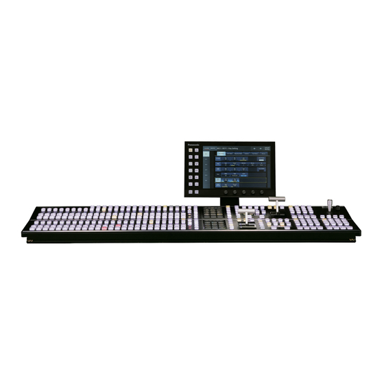
Page 21: Control Panel Av-Hs60C1/Av-Hs60C2
Chapter 3 Part Names and Functions — Control Panel AV‑HS60C1/AV‑HS60C2 Control Panel AV‑HS60C1/AV‑HS60C2 Operation panel SHOT MEMORY ME1 ME1 ME1 PinP PinP WIPE WIPE WIPE SHFT 0s15f 1s00f 1s00f 1s00f CAMERA CAMERA CAMERA CAMERA CAMERA CAMERA CAMERA CAMERA CAMERA CAMERA VTR1 VTR2 VTR3... - Page 22 Chapter 3 Part Names and Functions — Control Panel AV‑HS60C1/AV‑HS60C2 3 Source name display panels (This function will be available in V2.00.00 or higher.) Displays applications of the crosspoint buttons. The display settings of the source name display panels can be made from the <CONF> button on the top menu →...
- Page 23 Chapter 3 Part Names and Functions — Control Panel AV‑HS60C1/AV‑HS60C2 Transition area PinP PinP WIPE WIPE WIPE 0s15f 1s00f 1s00f 1s00f 2s00f 1 Transition target selection buttons (<BKGD>/<KEY1>/<KEY2>/<KEY3>/<KEY4>) Sets the operation target for the next transition to be executed when the fader lever or <AUTO>/<CUT> button is operated. 2 <MCRO ATCH>...
- Page 24 Chapter 3 Part Names and Functions — Control Panel AV‑HS60C1/AV‑HS60C2 r Transition status display Fig. 1 Fig. 2 Fig. 3 Fig. 4 The transition status display at the left side of the fader lever indicates not the lever position but the amount of transition, and also works during auto transition.
-
Page 25: Front Panel
SDHC memory card: 4 GB to 32 GB For the latest information not available in the Operating Guide, visit the following website. http://pro-av.panasonic.net/ (English only) f Keep the following points in mind when using or storing memory cards. - Avoid high temperatures/humidities. -
Page 26: Rear Panel
Chapter 3 Part Names and Functions — Control Panel AV‑HS60C1/AV‑HS60C2 Rear panel MAIN FRAME MENU PANEL DVI-D COM1 (M) COM2 (RS-232) GPI I/O 1 <AC IN 1>/<AC IN 2> terminals (signal: AC) Connects one end of the supplied AC cable to this terminal and the other end to the AC outlet. (AC 100 V to 240 V, 50 Hz/60 Hz) f The supplied AC cable has a 3-pin plug with a grounding terminal. -
Page 27: Menu Panel Av-Hs60C3
Chapter 3 Part Names and Functions — Menu Panel AV‑HS60C3 Menu Panel AV‑HS60C3 Operation panel 1 Top menu buttons (<ME1>, <ME2>, <DSK MISC>, <SYS>, <IN OUT>, <MV>, <PLUG IN>, <MEM>, <PRJ>, <CONF>) Selects the first hierarchy of the menu. 2 Split‑screen buttons (<MENU MODE>, <WFM VECT>) Switches the display of the menu screen. -
Page 28: Rear Panel
Chapter 3 Part Names and Functions — Menu Panel AV‑HS60C3 Display position Display content Upper left Images selected in the DISP bus are displayed. Upper right The WFM (waveform monitor) or VECTOR (vectorscope) for the video selected in the DISP bus is displayed. Bottom The menu will be displayed. -
Page 29: Chapter 4 Preparations
Preparations Chapter 4 This chapter describes basic operations and matters to be performed prior to use. -
Page 30: Turning Power On/Off
Chapter 4 Preparations — Turning power on/off Turning power on/off Turning power on Set the <POWER> switches of the Main Frame AV‑HS60U1/AV‑HS60U2 and the Control Panel AV‑HS60C1/AV‑HS60C2 to <ON>. f For the redundant power supply model (AV-HS60U2, AV-HS60C2), set both <POWER> switches of the power supply 1and the power supply 2 to <ON>. -
Page 31: Basic Menu Operations
Chapter 4 Preparations — Basic menu operations Basic menu operations This section describes basic operations of the menu. Connect with the Menu Panel AV-HS60C3 or general-purpose DVI monitor to perform menu operations. This document is written based on the operations with the Menu Panel AV-HS60C3. Operations may differ depending on the connected devices. -
Page 32: Numeric Entry Item Operations
Chapter 4 Preparations — Basic menu operations 8 [Default Setting] button Initializes the corresponding pages when the menu tab or the function menu is selected while the button is selected. 9 Menu tab Selects the third hierarchy of the menu. 10 Page Makes various settings. -
Page 33: Text Entry Item Operations
Chapter 4 Preparations — Basic menu operations 10 [Trim] Enters differential values to change the numeric values. This item is not displayed for the time entry. Select [Trim], and then enter the “numeric value” or “minus” + “numeric value” after the current numeric values display. After entering the differential values, press [Enter] to reflect the numeric values converted in the display format corresponding to the item in the entry field. -
Page 34: Color Settings Menu Operations
Chapter 4 Preparations — Basic menu operations 4 Alphanumerics, symbols Selects the alphanumerics or symbols you want to enter in the entry field. 5 [Shift] Switches the keyboard display. (Uppercase, lowercase) 6 [Space] Enters a space in the entry field. 7 [BS] Erases the last character in the entry field. -
Page 35: Other Buttons
Chapter 4 Preparations — Basic menu operations Other buttons List box The selection screen opens. When the item is selected, the screen closes, and the item is displayed at the lower part of the list box. Depending on the function, after selecting the item, select [OK] to close the screen. Radio button Select an item from multiple options. -
Page 36: Basic Operations For The Multi-Selection Panel Area
Chapter 4 Preparations — Basic operations for the multi‑selection panel area Basic operations for the multi‑selection panel area The multi-selection panel area is a color liquid crystal panel with buttons, which integrates wipe pattern selection and various memory operations. 1 Mode selection button Switches the mode using the buttons at the right side of the multi-selection panel area. -
Page 37: Shot Memory Menu
Chapter 4 Preparations — Basic operations for the multi‑selection panel area Shot memory menu Press the <SHOT MEM> button on the multi-selection panel area to display the shot memory menu. Register and play back the 81 register memories (9 pages×9 memories). Pages 1 to 9 can be specified for the page numbers of the memories. -
Page 38: Event Memory Menu
Chapter 4 Preparations — Basic operations for the multi‑selection panel area Event memory menu Press the <EVNT MEM> button on the multi-selection panel area to display the event memory menu. Play back the 81 register memories (9 pages×9 memories). Pages 1 to 9 can be specified for the page numbers of the memories. Numbers 1 to 9 can be specified as the respective memory numbers for the specified page numbers. -
Page 39: Video Memory Menu
Chapter 4 Preparations — Basic operations for the multi‑selection panel area Video memory menu Press the <VMEM> button on the multi-selection panel area to display the video memory menu. Record or play back the moving image memories (Clip) and still image memories (Still), and save or recall the register memories. The current thumbnail display will be available in V2.00.00 or higher. -
Page 40: Plug-In Menu
Chapter 4 Preparations — Basic operations for the multi‑selection panel area [OP] Moves to the [CHANNEL SELECT] menu. Stops recording Clip for the operation target. [STOP] f Operations are impossible for [STILL1] to [STILL4]. Records the source selected with the VMEM bus in the video memory for the [REC] operation target. -
Page 41: Menu Delegation Function
Chapter 4 Preparations — Menu delegation function Menu delegation function When a button on the Control Panel is double-clicked, the menu screen displayed on the Menu Panel AV-HS60C3 or the multi-selection panel area can be switched. At the same time, the normal operation activated when the button is pressed is also executed. Enabling/disabling the menu delegation function Enable/disable the menu delegation function at the Menu Panel AV-HS60C3 and the multi-selection panel area separately. -
Page 42: Various Settings
Chapter 4 Preparations — Various settings Various settings Network settings Configure the network for the Control Panel AV‑HS60C1/AV‑HS60C2 and the Main Frame AV‑HS60U1/AV‑HS60U2. Configuring the network for the Control Panel AV‑HS60C1/AV‑HS60C2 The terminals connected to the Main Frame AV-HS60U1/AV-HS60U2 differ depending on the number of Control Panel AV-HS60C1/AV-HS60C2. f When only one panel is connected Connect the Control Panel AV-HS60C1/AV-HS60C2 to the <PANEL>... -
Page 43: Button Settings
Chapter 4 Preparations — Various settings [Frame Buffer] tab Make the settings for DVI-D input signals. [Status] tab Displays the information on the images for DVI-D input signals. Select the <IN OUT> button → [C/C IN 25‑30], [C/C IN 31‑32] → [SDI IN 25] to [SDI IN 32] tabs, and make the color corrector settings. -
Page 44: Setting Multiview Displays
Chapter 4 Preparations — Various settings [Down Converter] tab Makes the settings for down-converters built into the <SDI OUT 14>/<SDI OUT 16> terminals. Select the <IN OUT> button → [C/C OUT] → [SDI OUT 13] to [SDI OUT 16] tabs, and make the color corrector settings. f This function will be available in V2.00.00 or higher. -
Page 45: Chapter 5 Basic Operations
Basic Operations Chapter 5 This chapter describes menu operations. -
Page 46: Background Transition
Chapter 5 Basic Operations — Background transition Background transition Selecting a bus Select sources to be used for background transitions. Press the crosspoint buttons. f Depending on the operating status, the buttons pressed will light in one of three color patterns. Color when lit* Type Description... - Page 47 Chapter 5 Basic Operations — Background transition r Setting the transition time Select the <ME1>/<ME2> button → [BKGD] → [Transition] tab. Set [Time] in the [Transition] column. f Set the transition time. NOTE t The units used for time display of the unit can be set to either in seconds/frame or in frames. (page 121) –...
-
Page 48: Wipe
Chapter 5 Basic Operations — Wipe Wipe Selecting the wipe pattern for background transition Set the wipe pattern for background transition. Select the <ME1>/<ME2> button → [BKGD] → [BKGD Pattern] tab. Set an item in [Pattern] in the [BKGD Pattern] column. f Select the wipe pattern for background transition. -
Page 49: Modifying Wipe
Chapter 5 Basic Operations — Wipe Set [Width], [Soft], and [Fill] in the [Border] column. [Width] Sets the border width. [Soft] Sets the amount of soft effect. Select the image to fill in the border area from [Matte], [UTIL1], or [UTIL2]. When [Matte] is selected, the border color can [Fill] be set using [Hue], [Sat], [Lum], or [Color Palette] in the [Border Color] column. - Page 50 Chapter 5 Basic Operations — Wipe f These can be set only when the target pattern is selected in the background. Either operate the fader lever or press the <AUTO> button to check the wipe operation. Example) When [X-Pos] is set to [−50], and [Y-Pos] is set to [−50] The next screen (or key) appears from the bottom left, and wipes in towards the center of the screen.
-
Page 51: Key
Chapter 5 Basic Operations — KEY Combine the background image with another image. The key definition can be adjusted, and an edge can be added to the combined image. The unit comes with four keys for each ME. The functional differences between <KEY1>/<KEY2>/<KEY3>/<KEY4> buttons and <DSK1>/<DSK2>/<DSK3>/<DSK4> buttons are as follows. <DSK1>... -
Page 52: Selecting The Key Source
Chapter 5 Basic Operations — KEY Does not cut key fill with a key signal. The part of key fill not cut out with the key signal is superimposed on the background image. This item is used when key fill source has been cut with a key signal beforehand using an external [On] device. -
Page 53: Key Wipe Transition
Chapter 5 Basic Operations — KEY Select the transition mode. f Press the <MIX> button to MIX the background image with a key. f Press the <WIPE> button to execute transition in the pattern selected as the wipe pattern on the menu. f Transition mode can be set separately for key in and key out. - Page 54 Chapter 5 Basic Operations — KEY f Set the start position of the next pattern waveform. - WIPE: 11, 12, 13, 14, 15 - SQ: 41, 42, 43, 44, 45 Select an item in [In=Out] in the [Wipe Out]/[SQ Out] column. [Off] Sets the start position of pattern waveform separately for key in and key out.
-
Page 55: Key Output
Chapter 5 Basic Operations — KEY Key output ME1 and ME2 output the following signals. For details, refer to “System Menu” (page 125). f ME1PGM, ME2PGM: Outputs program signals combined according to the transition setting. f ME1PVW, ME2PVW: Outputs preview signals of BKGD and KEY1 to KEY4 selected in next transition. To switch the screen to the preview screen for chroma key adjustment of the relevant keyer, use the <ME1>/<ME2>... - Page 56 Chapter 5 Basic Operations — KEY Displays the preview image selected using [View] in the [Sample] column. The sample marker is displayed. [Key1] ‑ [Key4] Because this is a common setting for [Key1] to [Key4], changing this setting for one key changes the setting of all the other keys.
- Page 57 Chapter 5 Basic Operations — KEY Set [X‑Pos], [Y‑Pos], and [Size] in the [Sample Area] column. f Set the position and size of the sample marker at the position of noise (black dots) in the foreground image. After setting the sample area, select [Sampling] in the [Sampling] column. f The noise in the area that has been set is now removed, and the foreground image is restored.
- Page 58 Chapter 5 Basic Operations — KEY f For details on [Clean BG Noise], refer to “Removing noise in the background image” (page 56). f For details on [Clean FG Noise], refer to “Removing noise in the foreground image” (page 56). f For details on [Spill Sponge], refer to “Removing color irregularity in the detail areas”...
- Page 59 Chapter 5 Basic Operations — KEY [Matte Sponge] makes the semi-transparent parts non-transparent, but does not change the color to the original color. (When the operation of [Clean FG Noise] is performed, the image returns to the original state including color information.) r [Make FG Trans] Increase transparency of the low transparency area in the foreground image.
-
Page 60: Key Decorations
Chapter 5 Basic Operations — KEY Key decorations Add a border, shadow, or other edge to the key. Setting the key edge [Border] [Drop] (Top) [180] [225] [270] [Shadow] [Outline] (Left) [135] [315] (Right) [90] [45] (Bottom) Fig. 1 Fig. 2 Select the <ME1>/<ME2>... -
Page 61: Masking The Key Signals
Chapter 5 Basic Operations — KEY Masking the key signals Mask the key signals using the mask signal of the box pattern. The following figure is the status when [Type] is set to [ForeGround], and [Invert] is set to [Off]. [50] Video signal range [Top]... -
Page 62: Pinp (Picture In Picture)
Chapter 5 Basic Operations — KEY PinP (Picture in Picture) Select PinP as the key type to combine the background image with key fill as a sub‑screen. (The transition effect is fixed at MIX.) Since PinP uses DVE effects, the image is delayed by one frame. Setting the PinP shape [Square] (square), [Circle] (circle),[Heart] (heart), [Star] (star), or [Flower] (flower) can be selected as the shape used for combining PinP images. - Page 63 Chapter 5 Basic Operations — KEY Item Description Makes the coordinates and rotation angle [Center] symmetrical to the center. NOTE t Do not set each other, such as selecting [Key2] in [Key1] and selecting [Key1] in [Key2] at [Target] in the [Sync] column. Normal operation may not be performed if set each other.
- Page 64 Chapter 5 Basic Operations — KEY Set [Left], [Top], [Right], and [Bottom] in [Trim Adjust1]/[Trim Adjust2]. f Set the trimming value. The [Left] setting cannot exceed the [Right] setting (and vice versa), and the [Top] setting cannot exceed the [Bottom] setting (and vice versa).
-
Page 65: Dsk (Downstream Key)
Chapter 5 Basic Operations — DSK (Downstream key) DSK (Downstream key) Combine characters or other images with the background image of ME1PGM or ME2PGM output. To select ME1PGM or ME2PGM output, use the <SYS> button on the top menu → [MAIN FRAME] → [DSK] → [Assign] in the [Config] column. (page 133) Selecting the DSK type Set the key type on the Menu Panel AV-HS60C3. -
Page 66: Dsk Transition
Chapter 5 Basic Operations — DSK (Downstream key) DSK transition Operating in the DSK operation area Press the <DSK1 TRNS> to <DSK4 TRNS> buttons in the transition area to execute a transition automatically with the transition time of respective keys set on the menu. - Page 67 Chapter 5 Basic Operations — DSK (Downstream key) Setting the DSK edge [Border] [Drop] (Top) [180] [225] [270] [Shadow] [Outline] (Left) [135] [315] (Right) [90] [45] (Bottom) Fig. 1 Fig. 2 Select the <DSK MISC> button → [DSK1] to [DSK4] → [Setting] tab. Select an item in [Type] in the [Edge] column.
-
Page 68: Masking The Dsk
Chapter 5 Basic Operations — DSK (Downstream key) Masking the DSK Mask the key signals using the mask signal of the box pattern. The following figure is the status when [Type] is set to [ForeGround], and [Invert] is set to [Off]. -
Page 69: Setting [Dsk On Link]
Chapter 5 Basic Operations — DSK (Downstream key) Setting [DSK On Link] To perform transition with the <DSK1 TRNS> to <DSK4 TRNS> buttons, set [DSK1] through [DSK4] at the same time. Select the <DSK MISC> button → [MISC] → [Misc] tab. Select an item in [DSK1] to [DSK4] in the [DSK On Link] column. -
Page 70: Usk (Upstream Key)
Chapter 5 Basic Operations — USK (Upstream key) USK (Upstream key) Combine characters or other images with the input image in the input area. Combine key sources generated using the four USK lines with respective source signals to handle them as sources with a telop without using ME. In addition, a 4:3 source of SD can be handled as a source by placing CG sources on both of its wings. -
Page 71: Selecting The Source Type
Chapter 5 Basic Operations — USK (Upstream key) Selecting the source type Select the <DSK MISC> button → [UP STREAM KEYER] → [USK1] to [USK4] tabs. Select an item in [Source Type] in the [Key] column. f Select the mode to link selection of key source signal with key fill selection. The selection status is stored for each source signal. [Self Key] Uses the source selected in the key fill bus column as the key source signal. -
Page 72: Adjusting The Luminance Key/Linear Key
Chapter 5 Basic Operations — USK (Upstream key) Adjusting the luminance key/linear key Adjust the luminance key and linear key definition. Select the <DSK MISC> button → [UP STREAM KEYER] → [USK1] to [USK4] tabs. Set [Clip], [Gain], and [Density] in the [Key Adjust] column. [Clip] Sets the reference level for creating key signals. -
Page 73: Image
Chapter 5 Basic Operations — IMAGE IMAGE NOTE t This function will be available in V2.00.00 or higher. Setting image effects Four types of effects, paint, monochrome color, mosaic, and defocus can be set to the KEY1FILL, KEY2FILL, PGM/A, and PST/B bus sources. f The [Key1] tab can set bus sources of KEY1FILL, the [Key2] tab can set bus sources of KEY2FILL, and the [BKGD] tab can set bus sources of PGM/A and PST/B. -
Page 74: Color Corrector
Chapter 5 Basic Operations — Color corrector Color corrector The unit can correct the colors of video signals because its terminals <SDI IN 25> to <SDI IN 32>, and <SDI OUT 13> to <SDI OUT 16> are equipped with the color corrector function. NOTE t This function will be available in V2.00.00 or higher. -
Page 75: Tone Curve
Chapter 5 Basic Operations — Color corrector Tone curve Correct the tone of input images. Set the tone curve to adjust the screen brightness and contrast. Adjust R, G, and B separately to adjust white balance or tone. 1: [Tone1 Black] 2: [Tone2 Gray L] 3: [Tone3 Gray H] 4: [Tone4 White]... - Page 76 Chapter 5 Basic Operations — Color corrector Set the amount of gain and hue in the [CC B‑Mg/Mg]/[CC Mg‑R/R]/[CC R‑Ye/Ye]/[CC Ye‑G/G]/[CC G‑Cy/Cy]/[CC Cy‑B/B] column. [B‑Mg Gain], [Mg Gain], [Mg‑R Gain], [R Gain], [R‑Ye Gain], [Ye Gain], [Ye‑G Gain], [G Gain], [G‑Cy Gain], [Cy Gain], [Cy‑B Gain], Sets the gain value.
-
Page 77: Internal Color Signals
Chapter 5 Basic Operations — Internal color signals Internal color signals The unit supports two lines of internal color signals. Setting the color background Set the color of the color background to be used by the bus. The color can be set by setting the hue (Hue), saturation (Sat), and luminance (Lum), or by recalling the preset eight colors. The recalled colors can also be adjusted using [Hue], [Sat], and [Lum]. -
Page 78: Switching The Aux Output
Chapter 5 Basic Operations — Switching the AUX output Switching the AUX output Selecting the AUX output sources Display the AUX output image on the monitor using the output settings or the settings of the MultiView display. Press one of the KEY bus selector buttons <AUX 1/2> to <AUX 15/16> of ME1 to select odd number buses among the AUX1 bus to the AUX15 bus. To select even number buses among the AUX2 bus to the AUX16 bus, press <AUX 1/2>... -
Page 79: Memory
Chapter 5 Basic Operations — Memory Memory The unit has the following memory functions to store setting data. f Shot memory (page 79) f Event memory (page 81) f Macro memory (page 87) f Key preset (page 90) f Key source preset (page 123) f Preset memory of background wipe (page 36) NOTE t Event memory, macro memory, key preset, and key source preset will be available in V2.00.00 or higher. - Page 80 Chapter 5 Basic Operations — Memory f The [Misc] screen is displayed. Select a file icon and set this item to [On] to protect the relevant file. The protected file is not deleted even when [Delete] [Protect]* is selected. [Rename]* Select [Rename] after selecting a file icon to change the file name using the on‑screen keyboard.
-
Page 81: Event Memory
Chapter 5 Basic Operations — Memory [XPT] [ME1] [BKGD] BKGD [Key1] [Key2] [Key3] [Key4] [A/B XPT] Key1 Key2 Key3 Key4 [ME2] BKGD Key1 Key2 Key3 Key4 [Key XPT] [DSK] Key1 Key2 Key3 Key4 [AUX] [CBGD] [AUX Sel1]: [All], [AUX1] - [AUX16] [AUX Sel2]: [AUX1] - [AUX16] CBGD1 [AUX Sel3]: [AUX1] - [AUX16]... - Page 82 Chapter 5 Basic Operations — Memory - When the same register memory page in the event memory is being played back - The same resource is being used in the shot memory and the event memory r Timeline A timeline is a group of events which have been placed on the time axis. r Event points and edit points On a timeline, the position where an event has been registered is called the event point, and the event currently being edited is called the current event.
- Page 83 Chapter 5 Basic Operations — Memory Select [New] in the [Edit1] column to initialize the work memory. f When this operation is performed, the timeline currently in the work memory is deleted. If it is required, register the timeline in a register memory of the event memory.
- Page 84 Chapter 5 Basic Operations — Memory Moves to the first event point. [Lead] [<Step] Moves to the previous event point. [>Step] Moves to the next event point. [Last] Moves to the last event point. Set [Play], [Pause], and [Reverse] in the [Control2] column. [Play] Plays back an event memory.
- Page 85 Chapter 5 Basic Operations — Memory Select an item in the [Control1] column. Moves to the first event point. [Lead] [<Step] Moves to the previous event point. [>Step] Moves to the next event point. [Last] Moves to the last event point. Select an item in [Play Mode] in the [Control1] column.
- Page 86 Chapter 5 Basic Operations — Memory Select [Misc] in the [Register] column. f The [Misc] screen is displayed. Select a file icon and set this item to [On] to protect the relevant file. The protected file is not deleted even when [Delete] [Protect]* is selected.
-
Page 87: Macro Memory
Chapter 5 Basic Operations — Memory Select an item in [Clip1] to [Clip4] in the [Detail Clip] column. [On] Sets as a memory target. [Off] Does not set as a memory target. Select an item in [AUX Sel1] to [AUX Sel5] in the [Detail AUX] column. f Select items from [AUX1] to [AUX16]. - Page 88 Chapter 5 Basic Operations — Memory [Play Cancel] Forcibly terminates the macro being played back. Select an item in the [Work Status] column. [Current Event] Displays the number of current events in the work memory. [Total Event] Displays the total number of events in the work memory. [Used] Displays the usage of the work memory.
- Page 89 Chapter 5 Basic Operations — Memory f When [Recall] is selected, playback target items cannot be selected. [View] Fixed to icon display. [Page] Switches pages. [Cancel] Closes the [Recall] screen without recalling the target. [OK] Closes the [Recall] screen after recalling the target. Editing macro register memories Delete a registered register memory or change file names.
-
Page 90: Key Preset
Chapter 5 Basic Operations — Memory NOTE t The <MCRO ATCH> button in the transition area on the Control Panel AV-HS60C1/AV-HS60C2 switches enabled/disabled status of the macro attach function assigned to the relevant buttons in the ME. - When it is turned on, the macro attach function is enabled. - The button to which the macro attach function is applied blinks while holding down the button. -
Page 91: Video Memory
Chapter 5 Basic Operations — Video memory Video memory The unit can store and use the still image memory (Still) and the moving image memory (Clip), each in four channels. The menu screen and the thumbnail display of the multi-selection menu panel will be available in V2.00.00 or higher. f Images with key signals can be saved in the video memory (still images and moving images). -
Page 92: Recording Moving Images (Clip)
Chapter 5 Basic Operations — Video memory Select an item in [Key Enable] in the [Rec1] column. f Set whether to record key signals at the same time. [Off] Does not record the key signals. [On] Records the key signals. Select an item in [Input Disp]/[Review] in the [Rec2] column. -
Page 93: Operating The Register Memory
Chapter 5 Basic Operations — Video memory [Input Disp] [Review] [CLIP] output When [Input Disp] is set to [On], the images on the VMEM bus are bypass displayed for the Clip1 to Clip4 outputs. [On] [On] When the recording of moving images is completed, the recorded moving images are played back for maximum four seconds, and then the images on the VMEM bus are displayed. -
Page 94: Using Image Files Created On A Computer
- HD/1080i: 1920×1080, HD/1080PsF: 1920×1080, HD/720p: 1280×720, SD/NTSC: 720×487, SD/PAL: 720×576 f If the size of an image is not appropriate, the image is centered without resizing and is output from AV-HS6000. If the size is too large, then the image is displayed with the portion which does not fit the size cut out. -
Page 95: Playing Back Moving Images (Clip)
Select the frame rate of the file to be loaded. This setting cannot be used when the frame rate is different from the AV-HS6000 system format. In the interlace mode and PsF mode, one file is expanded into two fields; and in the progressive mode, one file is equivalent to one frame. - Page 96 Chapter 5 Basic Operations — Video memory Playing back moving images Select the <MEM> button → [CLIP] → [Play Clip1] to [Play Clip4] tabs. Select [Play] in the [Play1] column. f Playback of the moving images starts. f [Current Time] displays the current playback position (time). f When [Pause] is selected, playback of moving images is suspended.
-
Page 97: Layout Of Display Icons
Chapter 5 Basic Operations — Video memory f When [Mode] in the [Play3] column is set to [Loop], the operation of [Lead] is performed. Amount of transition PGM-A PST-B In point Out point Clip playback [Mode]: [Lead] Standby Playback Standby Playback Standby Playback... - Page 98 Chapter 5 Basic Operations — Video memory 1 Channel name Displays channels from [Clip1] to [Clip4]. 2 Image of the 10th frame counting from the first frame Displays the image of the 10th frame counting from the first frame of the clip. (If the number of frames in a source is 10 frames or less, then the image of the frame one frame before the last image is displayed.) 3 Current frame 4 Recording time...
-
Page 99: Operating In The Multi-Selection Panel Area
Chapter 5 Basic Operations — Video memory 2 Register memory number 3 Protection mark Indicates that the moving image file is protected. 4 Number of frames in the moving image file 5 Time stamp when saved 6 Image file size 7 Source with key mark Indicates a source with key. -
Page 100: Project Management
Chapter 5 Basic Operations — Project management Project management The settings of the unit can be saved or loaded in/from three types of storage. f Memory card (optional) inserted in the memory card slot of the Control Panel AV-HS60C1/AV-HS60C2 f Storage Module AV-HS60D1 (optional) which can be mounted inside the Main Frame AV-HS60U1/AV-HS60U2 f Internal storage of the local computer connected to the <LAN>... -
Page 101: Editing Data In A Memory Card Or The Storage Module
Chapter 5 Basic Operations — Project management Select [OK]. f The project file is loaded. Editing data in a memory card or the storage module Delete data saved in a memory card or the Storage Module AV‑HS60D1 (optional), or change file names. Select the <PRJ>... -
Page 102: Storage
Chapter 5 Basic Operations — Storage Storage The settings of the unit can be saved or loaded in/from three types of storage. f Memory card (optional) inserted in the memory card slot of the Control Panel AV-HS60C1/AV-HS60C2 f Storage Module AV-HS60D1 (optional) which can be mounted inside the Main Frame AV-HS60U1/AV-HS60U2 f Internal storage of the local computer connected to the <LAN>... - Page 103 Chapter 5 Basic Operations — Storage f The data saved on memory cards may be lost as a result of misplacing the cards or performing erroneous operations. It is recommended that valuable data be saved on a computer or other device. Initializing a memory card To use a memory card in the unit, make sure to initialize the memory card using the unit.
-
Page 104: Storage Module
Chapter 5 Basic Operations — Storage Deleting files on the memory card To delete unnecessary project files and video memory (Still, Clip) files, select [Delete] on the [Misc] screen. To delete unnecessary files of other functions, delete using the computer. (page 94) Storage Module Project files and image files in the video memory can be saved and loaded in/from the optional Storage Module AV‑HS60D1 which is mounted inside the Main Frame AV-HS60U1/AV-HS60U2. -
Page 105: Chapter 6 Input/Output Signal Settings
Input/Output Signal Settings Chapter 6 This chapter describes the input/output signal settings. -
Page 106: Setting Input Signals
Chapter 6 Input/Output Signal Settings — Setting input signals Setting input signals [SDI IN 1] to [SDI IN 32] are used for SDI signal input. [DVI IN 1] and [DVI IN 2] are used for DVI-D signal input. f To configure the input signal settings, select the <IN OUT> button on the top menu → [SDI IN]/[DVI IN]. NOTE t 1080/24PsF, 1080/23.98PsF, 720/59.94p, and 720/50p will be available in V2.00.00 or higher. -
Page 107: Setting The Delay Amount
Chapter 6 Input/Output Signal Settings — Setting input signals Setting the delay amount The input signals can be delayed. f This function is enabled when [FS] in the [SDI IN 27]/[SDI IN 28]/[SDI IN 31]/[SDI IN 32] column is set to an item other than [Off]. Select the <IN OUT>... -
Page 108: Setting Dvi Input Signals
Chapter 6 Input/Output Signal Settings — Setting input signals Select an item in [Sharp] in the [SDI IN 27]/[SDI IN 28]/[SDI IN 31]/[SDI IN 32] column. f Set the extent of the edge sharpness for the images. [3] is the standard setting. Set this closer to [1] for less sharp edges, and to [5] for sharper edges. Set [Size] in the [SDI IN 27]/[SDI IN 28]/[SDI IN 31]/[SDI IN 32] column. - Page 109 Chapter 6 Input/Output Signal Settings — Setting input signals r List of DVI input scaling sizes HD/1080i HD/720p SD/NTSC SD/PAL DVI format [Mode] 1920×1080 1280×720 720×487 720×576 1440 [Fit-V] 1080 XGA (1024×768) [Fit-H] 1920 1280 [Full] 1080 1350 [Fit-V] 1080 SXGA (1280×1024) [Fit-H] 1920...
- Page 110 Chapter 6 Input/Output Signal Settings — Setting input signals HD/1080i HD/720p SD/NTSC SD/PAL DVI format [Mode] 1920×1080 1280×720 720×487 720×576 1728 1152 [Fit-V] 1080 WSXGA+ (1680×1050) [Fit-H] 1920 1280 [Full] 1080 1440 [Fit-V] 1080 UXGA (1600×1200) [Fit-H] 1920 1280 [Full] 1080 1728 1152...
-
Page 111: Displaying Video Input Signal Information
Chapter 6 Input/Output Signal Settings — Setting input signals HD/1080i HD/720p SD/NTSC SD/PAL DVI format [Mode] 1920×1080 1280×720 720×487 720×576 1920 1280 [Fit-V] 1080 1080/59.94p 1080/50p 1920 1080/59.94i 1280 1080/50i (1920×1080) [Fit-H] 1080 1920 1280 [Full] 1080 1920 1280 [Fit-V] 1080 720/59.94p 1920... -
Page 112: Setting Output Signals
Chapter 6 Input/Output Signal Settings — Setting output signals Setting output signals [SDI OUT 1] to [SDI OUT 16] are used for SDI signal output. The functions differ depending on the output signals. NOTE t 1080/24PsF, 1080/23.98PsF, 720/59.94p, and 720/50p will be available in V2.00.00 or higher. r List of settings by output signal f “l”... - Page 113 Chapter 6 Input/Output Signal Settings — Setting output signals System image Output image Item Description (SD) (HD) Reduces the image both horizontally and vertically so that the [Squeeze] aspect ratio is set to 4:3. Maintains the aspect ratio of the image, and reduces the [Edge Crop] image in accordance with the vertical resolution.
-
Page 114: Setting Multiview Displays
Chapter 6 Input/Output Signal Settings — Setting MultiView displays Setting MultiView displays The unit has 4 lines of MultiView display that can be split up to 16 screens. Setting the screen layout In [Split] of the [Pattern] column, select a split-screen layout from the following 9 options. [5-aSplit] [6-aSplit] [10-aSplit]... -
Page 115: Other Display Settings
Chapter 6 Input/Output Signal Settings — Setting MultiView displays [Tally Box] [Tally Label L] SDI IN 1 [Tally Label R] [Source Name] Select the <MV> button → [MV1‑4] → [MV1] to [MV4] tabs. Select an item in [Tally Group1] to [Tally Group4] in the [Tally Box]/[Tally Label L]/[Tally Label R] column. [On] Shows the tally displays. -
Page 116: Chapter 7 Config Menu
CONFIG Menu Chapter 7 This chapter describes how to operate the CONFIG menu displayed when the <CONF> button is pressed. -
Page 117: Disabling Button Operations
Chapter 7 CONFIG Menu — Disabling button operations Disabling button operations For each button or block, the operation can be disabled. Select the <CONF> button → [BUTTON INHIBIT] → [MainPanel]/[SubPanel1]/[SubPanel2] tab. [MainPanel] tab Assigns the main control panel. [SubPanel1] tab* Assigns the sub control panel 1 (the second Control Panel AV-HS60C1/AV-HS60C2). -
Page 118: Assigning Signals To Buttons
Chapter 7 CONFIG Menu — Assigning signals to buttons Assigning signals to buttons External video input signals and internally generated signals can be assigned to the crosspoint buttons (the PGM/A, PST/B, and KEY bus crosspoint buttons) in the crosspoint area. All buses in a single Control Panel AV-HS60C1/AV-HS60C2 have a common assignment. If the assignment of the signals selected by the crosspoint buttons is changed, the positions of the lit crosspoint buttons will be changed according to the changed assignment. -
Page 119: Setting The Source Name
Chapter 7 CONFIG Menu — Setting the source name Setting the source name Setting the source name display panel Set the display of the source name display panels on the crosspoint area and KEY/DSK operation area. Select the <CONF> button → [SOURCE NAME] → [Panel Name] tab. Select an item in [Type] in the column that displays the source name to be set. -
Page 120: Setting The Source Link
Chapter 7 CONFIG Menu — Setting the source link Setting the source link Setting the key coupling Linking the key fill signal and key source signal Two modes are available for the linking setting for the key fill signal and key source signal: f [Fill to Source]: When the key fill signal (master) is selected, the key source signal (slave) changes automatically. -
Page 121: Setting The Operation Mode
Chapter 7 CONFIG Menu — Setting the operation mode Setting the operation mode Setting the operation mode for the crosspoint buttons Selecting a bus using the SHIFT function The SHIFT function is used to assign four sources to one crosspoint button (the KEY, PGM/A, or PST/B crosspoint button) and change pages using the <2nd PAGE>/<3rd PAGE>... -
Page 122: Switching The Me Area In The Control Panel Av-Hs60C1/Av-Hs60C2
Chapter 7 CONFIG Menu — Setting the operation mode - 50i: Max. 39s24f - 50p: Max. 19s49f - 24PsF: Max. 41s15f - 23.98PsF: Max. 41s15f f The time that can be set in [Frame] is between 0 and 999 frames. FTB (Fade to Black) For DSKPGM1 and DSKPGM2 outputs, fade out from the program image to the black background screen, and fade in from the black ground screen to the program image. -
Page 123: Setting The Key Operation Mode
Chapter 7 CONFIG Menu — Setting the operation mode SHOT MEMORY ME1 ME1 ME1 PinP PinP WIPE WIPE WIPE SHFT 0s15f 1s00f 1s00f 1s00f CAMERA CAMERA CAMERA CAMERA CAMERA CAMERA CAMERA CAMERA CAMERA CAMERA VTR1 VTR2 VTR3 VTR4 CG1V CG2V STILL1V STILL2V CLIP1V... -
Page 124: Locking The Menu Operation
Chapter 7 CONFIG Menu — Locking the menu operation Locking the menu operation The menu setting that can be operated from the <CONF> button can be locked by each menu in the second hierarchy. Select the <CONF> button → [MENU LOCK] → [Menu Lock] tab. Select an item in [BUTTON INHIBIT], [XPT ASSIGN], [SOURCE NAME], [SOURCE LINK], and [OPERATE] in the [Menu Lock] column. -
Page 125: Chapter 8 System Menu
System Menu Chapter 8 This chapter describes how to operate the system menu displayed when the <SYS> button is pressed. -
Page 126: System Settings
Chapter 8 System Menu — System settings System settings Setting the video format function One system format (input/output signal) can be selected. NOTE t Do not change the format during any of the following operations: - When loading from a memory card or saving to a memory card - When loading from the Storage Module AV-HS60D1 or saving to the Storage Module AV-HS60D1 - When recording videos or still images Select the <SYS>... - Page 127 Chapter 8 System Menu — System settings Reference (System standard) Approx. 0.3H Line synchronizer range Internally fixed Approx. −0.3H to +0.7H delay Approx. 0.3H 1H output (+1H) Output phase variable range H phase ([−0.50H] to [0.49H]) V phase ([−100H] to [100H]) Line synchronizer range Internally fixed delay Approx.
- Page 128 Chapter 8 System Menu — System settings r When the sync signal (Reference) is set to [BB], [Tri‑level sync], or [Internal] [0H] [Output Phase] [System] [1H] Example 1) [Normal]/[U/C]/[Dot by [Mode] [Normal] [Normal] [U/C]/[Dot by Dot] Dot] Input signal [Strict] (forced) or [Strict] (forced) or [FS] [Strict] or [Acceptable]...
-
Page 129: Setting The Sync Signal
Chapter 8 System Menu — System settings Example 2) Input signal (Non-synchronized) Sync signal (Reference) 1F (frame) Output signal 1 Max. of 1F - Output signal 2 (90H) Max. of 1F Output signal 2 (1F) Max. of 2F - 90H Setting the sync signal The sync signal to be used by the system can be selected. -
Page 130: Network Settings
Chapter 8 System Menu — System settings The video is delayed by one frame (1F). [1F Fix] f The delay difference during transition (when [SQ], [SL], or [3D] is selected in the wipe pattern) and after transition will disappear. r Setting the delay amount MIX/WIPE SQ/SL/3D/Flying Key* Item... -
Page 131: Setting The Wfm/Vect Of Menu Panel Av-Hs60C3
Chapter 8 System Menu — System settings Setting the WFM/VECT of Menu Panel AV‑HS60C3 WFM and VECT which are displayed in Menu Panel AV-HS60C3 can be set. NOTE t This function will be available in V2.00.00 or higher. Setting the WFM (waveform monitor) Select the <SYS>... -
Page 132: Setting The Main Frame Av-Hs60U1/Av-Hs60U2
Chapter 8 System Menu — Setting the Main Frame AV‑HS60U1/AV‑HS60U2 Setting the Main Frame AV‑HS60U1/AV‑HS60U2 Setting the ME output and DSK output Video signals can be output in the ME1/ME2/DSK block as shown in the following figure. Each output can be assigned to the SDI OUT signal from the <IN OUT>... - Page 133 Chapter 8 System Menu — Setting the Main Frame AV‑HS60U1/AV‑HS60U2 Select an item in [Key1 Enable] to [Key4 Enable] in the [ME1 PVW]/[ME2 PVW] column. [Off] Does not output signals. [On] Outputs the preview signal of the corresponding keyer. Setting the DSKPGM1/DSKPGM2 output This unit has a DSKPGM1 output and a DSKPGM2 output.
-
Page 134: Setting The Control Panel Av-Hs60C1/Av-Hs60C2
Chapter 8 System Menu — Setting the Control Panel AV‑HS60C1/AV‑HS60C2 Setting the Control Panel AV‑HS60C1/AV‑HS60C2 Settings for the main control panel and sub control panel Panel brightness and saver time can be set in each Control Panel AV-HS60C1/AV-HS60C2. NOTE t Connection with the second or further Control Panel AV-HS60C1/AV-HS60C2 will be available in V2.00.00 or higher. Setting the touch buzzer The buzzer sound during touch screen operation can be enabled/disabled. - Page 135 Chapter 8 System Menu — Setting the Control Panel AV‑HS60C1/AV‑HS60C2 Select an item in [Low Tally] in the [Select Button] column. f Set the color of the button not included in the on-air output (except Preset). f Besides the KEY bus crosspoint buttons, the PGM/A bus crosspoint buttons, and the PST/B bus crosspoint buttons, other buttons excluding Preset are also included.
-
Page 136: Setting The External Connection
Chapter 8 System Menu — Setting the external connection Setting the external connection Setting a serial port The <COM4 (M/S)> port can be switched between master and slave connection. Select the <SYS> button → [PERIPHERAL] → [General] tab. Select an item in [Master/Slave] in the [MF COM4] column. [Master] A master connection is used. - Page 137 Chapter 8 System Menu — Setting the external connection f Select [Select] to filter the port list in the left column. You can select [All], [GPI In1‑6], [GPI In7‑12], or [GPI In13‑18]. Select the function to assign from the function list in the right column. f The input signal type can be selected from the right column function list by selecting [Type].
- Page 138 Chapter 8 System Menu — Setting the external connection f Select [Test Fire] to test the signal output operation of the set GPI port. The pulse of [LowEdge] is output for approximately 0.05 seconds. r GPI output function list This table describes cases when [ME1], [ME2], [DSK], or [OTHER] is selected in [Group Select]. [Group Select] Signal name Description...
-
Page 139: Maintenance Settings
Insert the memory card on which the update files are stored into the memory card slot. For the latest information, visit the following website. http://pro-av.panasonic.net/ (English only) Select the <SYS> button → [MAINTENANCE] → [Status] tab. Select an item in [Update File] in the [Update] column. -
Page 140: Startup Settings/Initialization
Chapter 8 System Menu — Maintenance settings r Display details [No Alarm] Shows that there are no problems. [Alarm] Shows that there is a problem. Not a target for determination. f When a power supply unit is not mounted [−] f When [Off] is selected in each item of [Alarm Enable] Enabling/disabling the alarm display Select the <SYS>... -
Page 141: Option Status Display And Activation
Chapter 8 System Menu — Maintenance settings NOTE t The function of the plug-in software initialization will be available in V2.00.00 or higher. The [with Plugin] item is not displayed. t When the settings data is initialized, video memory that has been saved to flash memory is lost. Data stored in Storage Module AV‑HS60D1 (optional) is not initialized. -
Page 142: Setting The Date And Time
Chapter 8 System Menu — Maintenance settings Resume data* Still Register* Clip Register* Project* Item ― [SSD Data] Flash memory settings data on the Main Frame AV-HS60U1/AV-HS60U2/MAINPROC unit Still Register data on Main Frame AV-HS60U1/AV-HS60U2/Storage Module AV-HS60D1 (optional) (Frame memory data from Still1 to Still4 are excluded from the backup) Clip Register data on Main Frame AV-HS60U1/AV-HS60U2/Storage Module AV-HS60D1 (optional) (Frame memory data from Clip1 to Clip4 are excluded from the backup) -
Page 143: Locking The Menu Operation
Chapter 8 System Menu — Locking the menu operation Locking the menu operation The menu setting that can be operated from the <SYS> button can be locked by each menu in the second hierarchy. Select the <SYS> button → [MENU LOCK] → [Menu Lock] tab. Select an item in [SYSTEM], [MAIN FRAME], [CTRL PANEL], [PERIPHERAL], and [MAINTENANCE] in the [Menu Lock] column. -
Page 144: Chapter 9 External Interfaces
External Interfaces Chapter 9 This chapter describes the terminals and signals of the unit. -
Page 145: Gpi Input/Output Settings And Alarm Output
GPI OUT, alarm connection examples (Fig. 1): Make sure that the following conditions are satisfied. Dielectric strength: Max. DC 24 V Current: Max. 50 mA GPI IN connection example (Fig. 2): Provide contact inputs. AV-HS6000 AV-HS6000 (Max. voltage: 24 V) Open collector output +3.3 V... -
Page 146: Gpi Input/Output Ports Of The Control Panel Av-Hs60C1/Av-Hs60C2
Chapter 9 External Interfaces — GPI input/output settings and alarm output Pin assignments and signal names of the <GPI IN> terminal Signal name Signal name Outside view Pin No. Pin No. GPI IN-1 GPI IN-13 GPI IN-2 GPI IN-14 GPI IN-3 GPI IN-15 GPI IN-4 GPI IN-16... -
Page 147: Serial Ports
Chapter 9 External Interfaces — Serial ports Serial ports Serial ports of the Main Frame AV‑HS60U1/AV‑HS60U2 There are 4 serial ports (RS-422) in Main Frame AV-HS60U1/AV-HS60U2. The <COM1 (M)>, <COM2 (M)>, and <COM3 (M)> terminals are exclusively for master connection. The <COM4 (M/S)> terminal can switch between the master connection and the slave connection through the <SYS>... -
Page 148: Plug-In Software
Chapter 9 External Interfaces — Plug‑in software Plug‑in software The unit allows plug-in software to be registered and functions to be added. Plug-in software can be registered, deleted, or started through the <PLUG IN> button on the top menu → [PLUGIN] → [List]. f For detailed information regarding the plug-in software, consult your dealer. -
Page 149: Chapter 10 Specifications
Specifications Chapter 10 This chapter describes the dimensions and specifications of this product. -
Page 150: Dimensions
Chapter 10 Specifications — Dimensions Dimensions Dimensions of the Main Frame AV‑HS60U1/AV‑HS60U2 Unit: mm (inch) (130 (5-1/8)) 2 (3/32) 423.4 (16-21/32) 482 (18-31/32) 465 (18-5/16) – 150 –... -
Page 151: Dimensions Of The Control Panel Av-Hs60C1/Av-Hs60C2
Chapter 10 Specifications — Dimensions Dimensions of the Control Panel AV‑HS60C1/AV‑HS60C2 Unit: mm (inch) 153.4 (6-1/32) 11.6 (15/32) 980 (38-19/32) 51 (2) 56 (2-7/32) 18 (23/32) 69.5 (2-3/4) 702 (27-5/8) 951 (37-7/16) – 151 –... -
Page 152: Dimensions Of The Menu Panel Av-Hs60C3
Chapter 10 Specifications — Dimensions Dimensions of the Menu Panel AV‑HS60C3 Unit: mm (inch) 290 (11-13/32) 4 (5/32) 11.8 (15/32) 30.3 (1-3/16) 75 (2-15/16) – 152 –... -
Page 153: Specifications
Chapter 10 Specifications — Specifications Specifications Main Frame AV‑HS60U1/AV‑HS60U2 Power supply AC 100 V to 240 V, 50 Hz/60 Hz Power consumption 110 W AV-HS60U2 supports redundant power supply. indicates safety information. Video terminal <SDI IN 1> to <SDI IN 32> terminals 32 lines f Connectors: BNC×32 f <SDI IN 27>, <SDI IN 28>, <SDI IN 31>, and <SDI IN 32>... - Page 154 Chapter 10 Specifications — Specifications <LTC IN> terminal This is the LTC (linear time code) input terminal f Connector: BNC f Impedance: 1 kΩ f Level: 1 to 2 V [p-p] Video delay time 1 line (H) When the frame synchronizer is set to [Off], and the up-converter is set to [Off] 1 frame (F) When the frame synchronizer is set to on, or the up-converter is set to [On] f When the signals have passed through PinP, DVE, MultiView, down-converter, or DVI-IN, a maximum delay of 1 frame is...
-
Page 155: Control Panel Av-Hs60C1/Av-Hs60C2
Chapter 10 Specifications — Specifications Control Panel AV‑HS60C1/AV‑HS60C2 Power supply AC 100 V to 240 V, 50 Hz/60 Hz Power consumption 40 W AV-HS60C2 supports redundant power supply. indicates safety information. Control terminal <MAIN FRAME> terminal Compatible with 100Base-TX and AUTO-MDIX (For Control Panel AV-HS60C1/AV-HS60C2 connection) f Connection cable (supplied with AV-HS60C1/AV-HS60C2): LAN cable (CAT5E), straight cable, STP (Shielded Twisted Pair), 10 m (32.8 ft) f Connector: RJ-45... -
Page 156: Menu Panel Av-Hs60C3
Chapter 10 Specifications — Specifications Menu Panel AV‑HS60C3 Power supply DC 12 V/0.54 A * Supplied from AV-HS60C1/AV-HS60C2 using the supplied cable Power consumption 6.48 W indicates safety information. <CONTROL PANEL> terminal Used only for the Control Panel AV-HS60C1/AV-HS60C2 f Connector: DVI-D f Because an independent signal format is used, DVI-D source cannot be displayed. -
Page 157: Chapter 11 Appendix
Appendix Chapter 11 This chapter describes the setting menu table and terms. -
Page 158: Setting Menu Table
Chapter 11 Appendix — Setting menu table Setting menu table This section describes the menu configuration. To perform menu operations, select the top menu → function menu → menu tab → column → item. For details on basic menu operations, refer to “Basic menu operations” (page 31). <ME1>/<ME2>... - Page 159 Chapter 11 Appendix — Setting menu table Setting item Setting item Column Item Default Column Item Default [Adjust] [Narrow] [Off], [0.5], [1.0], [1.5] [Off] [Sample Area] [X-Pos] [−50.00] - [50.00] [0.00] [Phase] [−4.0] - [4.0] [0.0] [Y-Pos] [−50.00] - [50.00] [0.00] [Sample] [Chroma PVW]...
- Page 160 Chapter 11 Appendix — Setting menu table [Chroma] tab Setting item Column Item Default [Sample Area] [X-Pos] [−50.00] - [50.00] [0.00] Setting item Column Item Default [Y-Pos] [−50.00] - [50.00] [0.00] ― ― [Auto Compute] [Auto Compute] [Size] [0.1] - [100.0] [10.0] ―...
-
Page 161: Dsk Misc> Button (Top Menu)
Chapter 11 Appendix — Setting menu table <DSK MISC> button (top menu) [DSK1] to [DSK4] (function menu) [Setting] tab Column Item Detailed setting Default [Edge Color] [Hue] [0.0] - [359.9] [0.0] Column Item Detailed setting Default [Sat] [0.0] - [100.0] [0.0] [DSK] [Type]... -
Page 162: Mem> Button (Top Menu)
Chapter 11 Appendix — Setting menu table [MISC] (function menu) Column Item Detailed setting Default [Misc] tab [DSK On Link] [DSK1] [Off], [On] [Off] Column Item Detailed setting Default [DSK2] [Off], [On] [Off] [DSK Priority] [DSK1] [1st], [2nd], [3rd], [4th] [4th] [DSK3] [Off], [On]... -
Page 163: Sys> Button (Top Menu)
Chapter 11 Appendix — Setting menu table [EVENT MEMORY] (function menu) This function will be available in V2.00.00 or higher. [MACRO] (function menu) This function will be available in V2.00.00 or higher. [KEY PRESET] (function menu) This function will be available in V2.00.00 or higher. <SYS>... - Page 164 Chapter 11 Appendix — Setting menu table [CTRL PANEL] (function menu) Column Item Detailed setting Default [Main Panel] tab [No Sel ME1]/ [XPT] [Input], [ColorGroup1] - [Input] Column Item Detailed setting Default [No Sel ME2] [ColorGroup8] [Touch Sound] [Touch Sound] [Off], [On] [Off] [Select Panel]...
-
Page 165: In Out> Button (Top Menu)
Chapter 11 Appendix — Setting menu table [GPI OUT] tab The assignment setting screen is displayed. [MAINTENANCE] (function menu) [Status] tab Column Item Detailed setting Default ― [Alarm Enable] [Power 1] [Off], [On] Column Item Detailed setting Default ― [Power 2] [Off], [On] ―... -
Page 166: Mv> Button (Top Menu)
Chapter 11 Appendix — Setting menu table [Status] tab [Up Converter] tab Column Item Detailed setting Default Column Item Detailed setting Default ― ― [SDI IN 1] - [SDI [Format] [SDI IN 27], [Scale] [Squeeze], [Edge Crop], [Squeeze] IN 32] [SDI IN 28], [Letter Box] ―... -
Page 167: Prj> Button (Top Menu)
Chapter 11 Appendix — Setting menu table <PRJ> button (top menu) [PROJECT] (function menu) [SD/SSD] tab Column Item Detailed setting Default ― [SSD] [Load] ([Load] screen) Column Item Detailed setting Default ― [Save] ([Save] screen) ― [SD] [Load] ([Load] screen) ―... - Page 168 Chapter 11 Appendix — Setting menu table [MENU LOCK] (function menu) [Menu Lock] tab Column Item Detailed setting Default [Menu Lock] [BUTTON [Off], [On] [Off] INHIBIT] [XPT ASSIGN] [Off], [On] [Off] [SOURCE [Off], [On] [Off] NAME] [SOURCE [Off], [On] [Off] LINK] [OPERATE] [Off], [On]...
-
Page 169: Glossary
Chapter 11 Appendix — Glossary Glossary Defined below are the terms used in this manual. Explanation Word AB Bus A bus control mode. By executing a transition, the A bus and B bus signals are output to the program images alternately. - Page 170 Chapter 11 Appendix — Glossary Explanation Word SDI (Serial Digital Interface) The standard by which video signals in the SD and HD formats are transmitted along a single coaxial cable. Self Key The function that creates key signals from key fill signals for combining keys. The memory in which the control panel statuses can be saved and recalled.
-
Page 171: Index
Index Index Key/DSK preset memory buttons Key output Accessories Key preset <AC IN 1> terminal 20, 26 Key source <AC IN 2> terminal 20, 26 Key transitions Alarm Key type Assigning signals to buttons <LAN> terminal Linear key 55, 66, 72 Background transition Locking the menu operation 124, 143... - Page 172 Index System settings Tone curve Top menu buttons Transition area Transition target selection buttons Transition type selection buttons Trimming 50, 63, 97 Turning power off Turning power on Up-converter Upstream key <USB> terminal Video input signals Video memory Video memory menu Wipe Wipe direction Wipe pattern...
- Page 173 Web Site: http://panasonic.net © Panasonic Corporation 2014...
Need help?
Do you have a question about the AV-HS6000 and is the answer not in the manual?
Questions and answers