D-Link DGS-3324SR User Manual
High-density layer 3 stackable gigabit ethernet switch
Hide thumbs
Also See for DGS-3324SR:
- Specifications (3 pages) ,
- User manual (363 pages) ,
- User manual (392 pages)

Related Manuals for D-Link DGS-3324SR


Summary of Contents for D-Link DGS-3324SR
- Page 1 D-Link ™ DGS-3324SR High-Density Layer 3 Stackable Gigabit Ethernet Switch User’s Guide...
- Page 2 Reproduction in any manner whatsoever without the written permission of D-Link Corporation is strictly forbidden. Trademarks used in this text: D-Link, the D-LINK logo are trademarks of D-Link Computer Corporation; Microsoft and Windows are registered trademarks of Microsoft Corporation. Other trademarks and trade names may be used in this document to refer to either the entities claiming the marks and names or their products.
-
Page 3: Table Of Contents
CONTENTS D-Link ™ DGS-3324SR......................i Intended Readers..........................ix Typographical Conventions ........................ ix Notes, Notices, and Cautions ....................x Safety Instructions........................x Safety Cautions ..............................x General Precautions for Rack-Mountable Products ..................xii Protecting Against Electrostatic Discharge ....................xiii Introduction ..........................1 Switch Description.......................... - Page 4 Connecting Devices to the Switch ..................... 14 Introduction to Switch Management..................15 Introduction............................15 Login to Web Manager ........................15 Web-based User Interface........................16 Areas of the User Interface..........................16 Web Pages..............................17 Basic Setup ............................18 Switch Information............................18 Switch IP Settings ............................18 Security IP Management Stations Configuration ...................21 User Accounts Management ..........................21 Admin and User Privileges............................22...
- Page 5 Understanding IEEE 802.1p Priority......................45 VLANs ................................46 Notes About VLANs on the DGS-3324SR ........................46 IEEE 802.1Q VLANs.............................46 802.1Q VLAN Packet Forwarding..........................47 802.1Q VLAN Tags ..............................47 Port VLAN ID................................49 Tagging and Untagging..............................49 Ingress Filtering ................................50 Default VLANs ................................50 Port-based VLANs ............................50 VLAN Segmentation..............................51 VLAN and Trunk Groups.............................51...
- Page 6 Configuring Layer 3 IP Networking ....................87 L3 Global Advanced Settings.........................87 Setting Up IP Interfaces ..........................88 MD5 Key................................90 Route Redistribution Settings.........................90 Static/Default Route ............................92 Static ARP Table............................93 Routing Information Protocol (RIP).......................94 RIP Version 1 Message Format............................95 RIP 1 Message................................96 RIP 1 Route Interpretation ............................96 RIP Version 2 Extensions.............................96 RIP2 Message Format ..............................96 Setting Up RIP ................................97...
- Page 7 SNMP Engine ID ..........................138 Monitoring ..........................139 Port Utilization..........................139 Packets ............................. 140 Received(RX)...............................141 UMB_cast(RX) ............................143 Transmitted (TX) ............................145 Errors ............................... 147 Received (RX)..............................147 Transmitted (TX) ............................149 Size ..............................151 Stacking Information ........................153 Device Status ........................... 154 MAC Address ..........................155 Switch History Log..........................
- Page 8 Switch Maintenance ......................175 TFTP Services..........................175 Download Firmware.............................175 Download Configuration File........................175 Upload Configuration...........................176 Upload Log..............................176 Ping Test ............................176 Save Changes........................... 177 Reset ..............................178 Reboot Device..........................179 Logout.............................. 179 Technical Specifications....................... 180 Glossary..........................182...
-
Page 9: Intended Readers
D-Link DGS-3324SR Layer 3 Stackable Gigabit Ethernet Switch Intended Readers The DGS-3324SR User Guide contains information for setup and management of the DGS-3324SR Switch. This guide is intended for network managers familiar with network management concepts and terminology. Typographical Conventions... -
Page 10: Notes, Notices, And Cautions
D-Link DGS-3324SR Layer 3 Stackable Gigabit Ethernet Switch Notes, Notices, and Cautions NOTE: A NOTE indicates important information that helps you make better use of your device. NOTICE: A NOTICE indicates either potential damage to hardware or loss of data and tells you how to avoid the problem. - Page 11 D-Link DGS-3324SR Layer 3 Stackable Gigabit Ethernet Switch • Do not push any objects into the openings of your system. Doing so can cause fire or electric shock by shorting out interior components. • Use the product only with approved equipment.
-
Page 12: General Precautions For Rack-Mountable Products
D-Link DGS-3324SR Layer 3 Stackable Gigabit Ethernet Switch General Precautions for Rack-Mountable Products Observe the following precautions for rack stability and safety. Also refer to the rack installation documentation accompanying the system and the rack for specific caution statements and procedures. -
Page 13: Protecting Against Electrostatic Discharge
D-Link DGS-3324SR Layer 3 Stackable Gigabit Ethernet Switch CAUTION: The system chassis must be positively grounded to the rack cabinet frame. Do not attempt to connect power to the system until grounding cables are connected. Completed power and safety ground wiring must be inspected by a qualified electrical inspector. -
Page 14: Introduction
The DGS-3324SR is a modular Gigabit Ethernet backbone switch designed for adaptability and scalability. The Switch provides a management platform and uplink to backbone for a stacked group of twelve DGS-3324SR Layer 3 switches in a ring or chain topology arrangement. Alternatively, the Switch can utilize up to twenty-four Gigabit Ethernet ports to function as a central distribution hub for other switches or switch groups, or routers. -
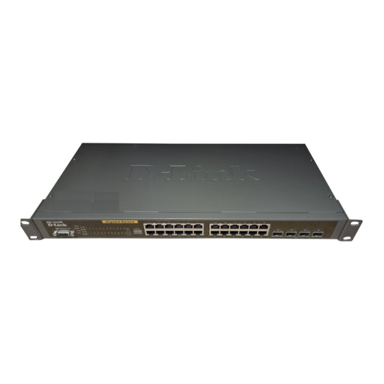
Page 15: Front-Panel Components
D-Link DGS-3324SR Layer 3 Stackable Gigabit Ethernet Switch • TFTP upgrade • Traffic Segmentation • SysLog support • Simple Network Time Protocol • Web GUI Traffic Monitoring Front-Panel Components The front panel of the Switch consists of LED indicators, an RS-232 communication port, and four SFP (Mini- GBIC) combo ports. -
Page 16: Rps Connector
Connect the optional external redundant power supply to the RPS connector. If the Switch’s internal power unit fails, the redundant power system automatically supplies power to the switch for uninterrupted operation. The switch supports the D-Link RPS-500 redundant power supply units. Management Options The system may be managed out-of-band through the console port on the front panel or in-band using Telnet or a web browser. - Page 17 D-Link DGS-3324SR Layer 3 Stackable Gigabit Ethernet Switch • RFC1907 (SNMPv2-MIB) • RFC2021 (RMON2) • RFC2096 IP Forwarding • RFC2233 Interface MIB • RFC2571 (SNMP Frameworks) • RFC2572 (Message Processing for SNMP) • RFC2573 (SNMP Applications) • RFC2574 (USM for SNMP) •...
-
Page 18: Installation
D-Link DGS-3324SR Layer 3 Stackable Gigabit Ethernet Switch Section 2 Installation Package Contents Before You Connect to the Network Switch Installation Connecting Stacked Switch Groups Gigabit Combo Ports External Redundant Power System Connecting the Console Port Password Protection SNMP Settings... -
Page 19: Switch Installation
D-Link DGS-3324SR Layer 3 Stackable Gigabit Ethernet Switch Switch Installation Installing the Switch Without the Rack 1. Install the Switch on a level surface that can safely support the weight of the Switch and its attached cables. The Switch must have adequate space for ventilation and for accessing cable connectors. -
Page 20: Connecting Stacked Switch Groups
D-Link DGS-3324SR Layer 3 Stackable Gigabit Ethernet Switch Figure 2-3. Install switch in equipment rack Connecting Stacked Switch Groups Up to 12 switches can be stacked together for Ring mode or Chain mode to a Master Unit or in tandem with a second master unit via the second 10Gig stacking port. - Page 21 D-Link DGS-3324SR Layer 3 Stackable Gigabit Ethernet Switch Figure 2-4. Ring (Bus) Topology Please note that the DGS-3324SRi is needed to connect a group of Switches in the Star topology, as shown below.
-
Page 22: Configuring A Switch Group For Stacking
That is, stacking port 1 may connect to 1 or 2, and stacking port 2 may connect to 2 or 1 Configuring a Switch Group for Stacking Follow the instructions below to configure the DGS-3324SR as the designated Master, and then to configure the slave units. -
Page 23: Unit Id Display For Switches In A Switch Stack
Success. DGS-3324SR:4#.... DGS-3324SR:4# To configure the same DGS-3324SR to function in a stacked group as the Slave, do the following: 1. At the CLI login prompt, enter config box_priority current_box_id 1 priority 2 and press the Enter key. 2. Successful configuration will be verified by a Success message. It takes a few seconds for the change to take effect. -
Page 24: External Redundant Power System
D-Link DGS-3324SR Layer 3 Stackable Gigabit Ethernet Switch simultaneously with its corresponding 10/100/1000BASE-T port. For example, if port 24x is used on the Mini GBIC module, port 24 is not available for the 10/100/1000BASE-T built-in port, and vice versa. External Redundant Power System The Switch supports an external redundant power system. -
Page 25: Connecting The Console Port
D-Link DGS-3324SR Layer 3 Stackable Gigabit Ethernet Switch NOTE: See the DPS-900 documentation for more information. CAUTION: Do not use the Switch with any redundant power system other than the DPS-900. Connecting the Console Port The Switch provides an RS-232 serial port that enables a connection to a computer or terminal for monitoring and configuring the switch. -
Page 26: Password Protection
Password Protection The DGS-3324SR does not have a default user name and password. One of the first tasks when settings up the Switch is to create user accounts. If you log in using a predefined administrator-level user name you have privileged access to the Switch’s management software. -
Page 27: Snmp Settings
The DGS-3324SR supports the SNMP versions 1, 2c, and 3. You can specify which version of the SNMP you want to use to monitor and control the Switch. The three versions of SNMP vary in the level of security provided between the management station and the network device. -
Page 28: Ip Address Assignment
D-Link DGS-3324SR Layer 3 Stackable Gigabit Ethernet Switch IP Address Assignment Each switch must be assigned its own IP Address, which is used for communication with an SNMP network manager or other TCP/IP application (for example BOOTP, TFTP). The Switch’s default IP address is 10.90.90.90. -
Page 29: Connecting Devices To The Switch
D-Link DGS-3324SR Layer 3 Stackable Gigabit Ethernet Switch Connecting Devices to the Switch After assigning IP addresses to the Switch, you can connect devices to the Switch. To connect a device to an SFP transceiver port: 1. Use your cabling requirements to select an appropriate SFP transceiver type. -
Page 30: Introduction To Switch Management
Restart System Introduction All software functions of the DGS-3324SR can be managed, configured and monitored via the embedded web- based (HTML) interface. The switch can be managed from remote stations anywhere on the network through a standard browser such as Netscape Navigator/Communicator or Microsoft Internet Explorer. The browser acts as a universal access tool and can communicate directly with the Switch using the HTTP protocol. -
Page 31: Web-Based User Interface
D-Link DGS-3324SR Layer 3 Stackable Gigabit Ethernet Switch Figure 3- 2. Enter Network Password window Leave both the User Name field and the Password field blank and click OK. This will open the Web-based user interface. The Switch management features available in the web-based manager are explained below. -
Page 32: Web Pages
D-Link DGS-3324SR Layer 3 Stackable Gigabit Ethernet Switch Area Function Presents a graphical near real-time image of the front panel of the Switch. This area displays the Switch’s ports and expansion modules, showing port activity, duplex mode, or flow control, depending on the specified mode. To the right of the Switch’s front panel is the current stacking configuration. -
Page 33: Basic Setup
D-Link DGS-3324SR Layer 3 Stackable Gigabit Ethernet Switch Basic Setup The subsections below describe how to change some of the basic settings for the Switch such as changing IP settings and assigning user names and passwords for management access privileges, as well as how to save the changes and restart the Switch. - Page 34 D-Link DGS-3324SR Layer 3 Stackable Gigabit Ethernet Switch Figure 3- 5. Configure Switch IP Settings NOTE: The Switch’s factory default IP address is 10.90.90.90 with a subnet mask of 255.0.0.0 and a default gateway of 0.0.0.0. To manually assign the Switch’s IP address, subnet mask, and default gateway address: -Select Manual from the Get IP From drop-down menu.
- Page 35 D-Link DGS-3324SR Layer 3 Stackable Gigabit Ethernet Switch network administrator. The fields which require entries under this option are as follows: Subnet Mask A Bitmask that determines the extent of the subnet that the Switch is on. Should be of the form xxx.xxx.xxx.xxx, where each xxx is a number (represented in decimal) between 0 and 255.
-
Page 36: Security Ip Management Stations Configuration
D-Link DGS-3324SR Layer 3 Stackable Gigabit Ethernet Switch Security IP Management Stations Configuration Go to the Security Management folder and click on Security IP; the following screen will appear. Figure 3- 6. Security IP Management Setup Use the Management Station IP Settings to select up to three management stations used to manage the Switch. -
Page 37: Admin And User Privileges
D-Link DGS-3324SR Layer 3 Stackable Gigabit Ethernet Switch Figure 3- 9. Modify User Accounts Modify or delete an existing user account in the User Account Modify Table. To delete the user account, click on the Delete button. To change the password, type in the New Password and retype it in the Confirm New Password entry field. -
Page 38: Factory Reset
D-Link DGS-3324SR Layer 3 Stackable Gigabit Ethernet Switch Figure 3- 10. Save Configuration window The Switch has two levels of memory, normal RAM and non-volatile or NV-RAM. To save all the changes made in the current session to the Switch’s flash memory, click the Save Configuration button. Click the OK button in the new dialog box that appears to continue. -
Page 39: Restart System
D-Link DGS-3324SR Layer 3 Stackable Gigabit Ethernet Switch Restart System The following menu is used to restart the Switch. Access this menu by clicking on the Reboot Device link in the Maintenance folder. Click the Yes after Do you want to save the settings? to instruct the Switch to save the current configuration to non-volatile RAM before restarting the Switch. -
Page 40: Advanced Settings
D-Link DGS-3324SR Layer 3 Stackable Gigabit Ethernet Switch Figure 3- 13. Switch Information The System Information page displays general information about the Switch including its MAC Address, Hardware Boot PROM and Firmware versions, and other optional information. You can also enter or change a System Name, System Location, and the name and telephone number of the responsible administrator in the System Contact. - Page 41 D-Link DGS-3324SR Layer 3 Stackable Gigabit Ethernet Switch Figure 3- 14. Switch Information − Advanced Settings The Advanced Settings menu options are summarized in the table below. Variables in the Advanced Settings menu of the Web Manager are as follows:...
- Page 42 D-Link DGS-3324SR Layer 3 Stackable Gigabit Ethernet Switch Multicast Router If this option is enabled and IGMP Snooping is also enabled, the Switch Only forwards all multicast traffic to a multicast-enabled router only. Otherwise, the Switch will forward all multicast traffic to any IP router.
-
Page 43: Configuration
D-Link DGS-3324SR Layer 3 Stackable Gigabit Ethernet Switch Section 4 Configuration Configuring Box Information Configuring Ports Configuring Port Mirroring Configuring Link Aggregation Configuring IGMP Configuring The Spanning Tree Configuring Forwarding and Filtering Configuring VLANs Configuring Traffic Control Configuring Port Security... -
Page 44: Configuring Ports
D-Link DGS-3324SR Layer 3 Stackable Gigabit Ethernet Switch Box Type The user may choose the model name of the Master switch in a stack to be the main configuring switch of that stack. Priority Displays the priority ID of the Switch. The lower the number, the higher the priority. -
Page 45: Configuring Port Mirroring
D-Link DGS-3324SR Layer 3 Stackable Gigabit Ethernet Switch To configure switch ports: 1. Choose the Unit from the pull-down menu. 2. Choose the port or sequential range of ports using the From…To… port pull-down menus. 3. Use the remaining pull-down menus to configure the parameters described below:... -
Page 46: Configuring Link Aggregation
Port trunk groups are used to combine a number of ports together to make a single high-bandwidth data pipeline. The DGS-3324SR supports up to 32 port trunk groups with 2 to 8 ports in each group. A potential bit rate of... - Page 47 D-Link DGS-3324SR Layer 3 Stackable Gigabit Ethernet Switch Figure 4- 4. Example of Port Trunk Group The Switch treats all ports in a trunk group as a single port. Data transmitted to a specific host (destination address) will always be transmitted over the same port in a trunk group. This allows packets in a data stream to arrive in the same order they were sent.
- Page 48 D-Link DGS-3324SR Layer 3 Stackable Gigabit Ethernet Switch the state of the link aggregation group. If two redundant link aggregation groups are configured on the switch, STP will block one entire group, in the same way STP will block a single port that has a redundant link.
-
Page 49: Lacp Port Setting
D-Link DGS-3324SR Layer 3 Stackable Gigabit Ethernet Switch Figure 4- 7. Link Aggregation Group Configuration window – Modify The user-changeable parameters are as follows: Parameter Description Group ID Select an ID number for the group, between 1 and 32. Type This pull-down menu allows you to select between Static and LACP (Link Aggregation Control Protocol.) LACP allows for the automatic detection of... - Page 50 D-Link DGS-3324SR Layer 3 Stackable Gigabit Ethernet Switch Figure 4- 8. LACP Port Setting and Information window The user may set the following parameters: Parameter Description Choose the number representing the Switch in the stack for which you Unit would like to change the LACP Port mode.
-
Page 51: Configuring Igmp
D-Link DGS-3324SR Layer 3 Stackable Gigabit Ethernet Switch After setting the previous parameters, click Apply to allow your changes to be implemented. The LACP Port Information Table shows which ports are active and/or passive. Configuring IGMP Internet Group Management Protocol (IGMP) snooping allows the Switch to recognize IGMP queries and reports sent between network stations or devices and an IGMP host. -
Page 52: Static Router Ports
D-Link DGS-3324SR Layer 3 Stackable Gigabit Ethernet Switch The following parameters may be viewed or modified: Parameter Description VLAN ID This is the VLAN ID that, along with the VLAN name, identifies the VLAN which the user wishes to modify the IGMP Snooping Settings for. - Page 53 D-Link DGS-3324SR Layer 3 Stackable Gigabit Ethernet Switch A router port has the following behavior: • All IGMP Report packets will be forwarded to the router port. • IGMP queries (from the router port) will be flooded to all ports.
-
Page 54: Configuring The Spanning Tree
802.1d STP will be familiar to most networking professionals. However since 802.1w RSTP has been recently introduced to D-Link managed Ethernet switches, a brief introduction to the technology is provided below followed by a description of how to set up 802.1 d STP and 802.1w RSTP. -
Page 55: 802.1D/802.1W Compatibility
D-Link DGS-3324SR Layer 3 Stackable Gigabit Ethernet Switch designated as edge ports transition to a forwarding state immediately without going through the listening and learning states. An edge port loses its status if it receives a BPDU packet, immediately becoming a normal spanning tree port. -
Page 56: Stp Port Settings
D-Link DGS-3324SR Layer 3 Stackable Gigabit Ethernet Switch Configure the following parameters and click the Apply button to implement them: Parameter Description This field can be toggled between Enabled and Disabled using the pull- Spanning Tree down menu. This will enable or disable the Spanning Tree Protocol (STP), Protocol <Disabled>... - Page 57 D-Link DGS-3324SR Layer 3 Stackable Gigabit Ethernet Switch Figure 4- 14. STP Port Settings In addition to setting Spanning Tree parameters for use on the switch level, the Switch allows for the configuration of groups of ports, each port-group of which will have its own spanning tree, and will require some of its own configuration settings.
-
Page 58: Configuring Forwarding & Filtering
D-Link DGS-3324SR Layer 3 Stackable Gigabit Ethernet Switch Cost(0=Auto) < 0 > A Port Cost can be set from 1 to 200000000. The lower the number, the greater the probability the port will be chosen to forward packets. Default port cost:... -
Page 59: Static Multicast Forwarding
D-Link DGS-3324SR Layer 3 Stackable Gigabit Ethernet Switch Parameter Description VLAN ID (VID) The VLAN ID number of the VLAN on which the above Unicast MAC address resides. MAC Address The MAC address to which packets will be statically forwarded. This must be a unicast MAC address. -
Page 60: Configuring Vlans
D-Link DGS-3324SR Layer 3 Stackable Gigabit Ethernet Switch Parameter Description Unit This is the Unit ID of a switch in a switch stack. The VLAN ID of the VLAN the corresponding MAC address belongs to. Multicast MAC The MAC address of the static source of multicast packets. This must be a Address multicast MAC address. -
Page 61: Vlans
VLANs without a network device performing a routing function between the VLANs. The DGS-3324SR supports IEEE 802.1Q VLANs and Port-Based VLANs. The port untagging function can be used to remove the 802.1Q tag from packet headers to maintain compatibility with devices that are tag-unaware. -
Page 62: 802.1Q Vlan Packet Forwarding
D-Link DGS-3324SR Layer 3 Stackable Gigabit Ethernet Switch Any port can be configured as either tagging or untagging. The untagging feature of IEEE 802.1Q VLANs allows VLANs to work with legacy switches that don’t recognize VLAN tags in packet headers. The tagging feature allows VLANs to span multiple 802.1Q-compliant switches through a single physical connection and... - Page 63 D-Link DGS-3324SR Layer 3 Stackable Gigabit Ethernet Switch field is equal to 0x8100, the packet carries the IEEE 802.1Q/802.1p tag. The tag is contained in the following two octets and consists of 3 bits of user priority, 1 bit of Canonical Format Identifier (CFI – used for encapsulating Token Ring packets so they can be carried across Ethernet backbones), and 12 bits of VLAN ID (VID).
-
Page 64: Port Vlan Id
D-Link DGS-3324SR Layer 3 Stackable Gigabit Ethernet Switch Port VLAN ID Packets that are tagged (are carrying the 802.1Q VID information) can be transmitted from one 802.1Q compliant network device to another with the VLAN information intact. This allows 802.1Q VLANs to span network devices (and indeed, the entire network, if all network devices are 802.1Q compliant). -
Page 65: Ingress Filtering
D-Link DGS-3324SR Layer 3 Stackable Gigabit Ethernet Switch Ingress Filtering A port on a switch where packets are flowing into the switch and VLAN decisions must be made is referred to as an ingress port. If ingress filtering is enabled for a port, the switch will examine the VLAN information in the packet header (if present) and decide whether or not to forward the packet. -
Page 66: Vlan Segmentation
D-Link DGS-3324SR Layer 3 Stackable Gigabit Ethernet Switch On port-based VLANs, NICs do not need to be able to identify 802.1Q tags in packet headers. NICs send and receive normal Ethernet packets. If the packet’s destination lies on the same segment, communications take place using normal Ethernet protocols. - Page 67 D-Link DGS-3324SR Layer 3 Stackable Gigabit Ethernet Switch Figure 4- 22. 802.1Q Static VLANs – Add To return to the Current 802.1Q Static VLANs Entries window, click the Show All Static VLAN Entries link. To change an existing 802.1Q VLAN entry, double-click on the selected entry in the Current 802.1Q Static VLANs Entries menu.
-
Page 68: Gvrp Settings
D-Link DGS-3324SR Layer 3 Stackable Gigabit Ethernet Switch Advertisement Enabling this function will allow the switch to send out GVRP packets to outside sources, notifying that they may join the existing VLAN. Port Allows an individual port to be specified as member of a VLAN. - Page 69 D-Link DGS-3324SR Layer 3 Stackable Gigabit Ethernet Switch Figure 4- 24. GVRP Settings and GVRP Table The following fields can be set: Parameter Description Displays the Unit ID of the switch − within the switch stack − that the VLAN Unit will be created on.
-
Page 70: Configuring Traffic Control (Broadcast/Multicast Storm Control)
D-Link DGS-3324SR Layer 3 Stackable Gigabit Ethernet Switch This field can be toggled using the space bar between Enabled and Disabled. Enabled enables the port to compare the VID tag of an incoming Ingress Check packet with the PVID number assigned to the port. If the two are different, the port filters (drops) the packet. -
Page 71: Configuring Port Security
D-Link DGS-3324SR Layer 3 Stackable Gigabit Ethernet Switch Figure 4- 25. Traffic Control Settings window Traffic or storm control is used to stop broadcast, multicast or ARP request storms that may result when a loop is created. The Destination Look Up Failure control is a method of shutting down a loop when a storm is formed because a MAC address cannot be located in the Switch’s forwarding database and it must send a packet to all... - Page 72 D-Link DGS-3324SR Layer 3 Stackable Gigabit Ethernet Switch Figure 4- 26. Port Security Settings window Click Apply to implement the changes on the Switch. The following parameters can be set: Parameter Description Unit Allows you to specify a switch in a switch stack using that switch’s Unit ID.
-
Page 73: Configuring Qos
CoS until there are no more packets for this CoS. The other CoS queues that have been given a nonzero value, and depending upon the weight, will follow a common weighted round-robin scheme. Remember that the DGS-3324SR has 8 priority queues (and eight Classes of Service) for each port on the Switch. - Page 74 D-Link DGS-3324SR Layer 3 Stackable Gigabit Ethernet Switch Figure 4- 27. Bandwidth Settings window The following parameters can be set or are displayed: Parameter Description Unit Allows you to specify a switch in a switch stack using that switch’s Unit ID.
-
Page 75: Qos Scheduling Mechanism Table
D-Link DGS-3324SR Layer 3 Stackable Gigabit Ethernet Switch This field allows you to enter the data rate, in kb/s, that will be the limit for Rate the selected port. Click Apply to set the Bandwidth control for the selected ports. Results of the Bandwidth Settings will be displayed directly below, in the Port Bandwidth Table. -
Page 76: 802.1P Default Priority
D-Link DGS-3324SR Layer 3 Stackable Gigabit Ethernet Switch Figure 4- 29. QoS Output Scheduling Configuration window Once you have assigned a priority to the port groups on the Switch, you can then assign this Class to each of the 7 levels of 802.1p priorities. -
Page 77: 802.1P User Priority
0 − the lowest priority − to 7 − the highest priority. Click Apply to implement your settings. 802.1p User Priority The DGS-3324SR allows the assignment of a User Priority to each of the 802.1p priorities. In the Configuration folder open the QoS folder and click 802.1p User Priority, to view the screen shown below. -
Page 78: Configuring Traffic Segmentation
D-Link DGS-3324SR Layer 3 Stackable Gigabit Ethernet Switch Figure 4- 31. User Priority Configuration window Once you have assigned a priority to the port groups on the Switch, you can then assign this Class to each of the 8 levels of 802.1p priorities. Click Apply to set your changes. -
Page 79: The System Log Server
Configuring traffic segmentation on the DGS-3324SR is accomplished in two parts. First you specify a switch from a switch stack, and then a port from that switch. Then you specify a second switch from the switch stack, and then you select which ports (or different ports on the same switch,) on that switch that you want to be able to receive packets from the switch and port you specified in the first part. - Page 80 D-Link DGS-3324SR Layer 3 Stackable Gigabit Ethernet Switch The parameters configured for adding and editing System Log Server settings are the same. See the table below for a description. Figure 4- 35. System Log Servers − Add The following parameters can be set:...
-
Page 81: Configuring Sntp Settings
D-Link DGS-3324SR Layer 3 Stackable Gigabit Ethernet Switch NTP subsystem log audit log alert clock daemon local use 0 (local0) local use 1 (local1) local use 2 (local2) local use 3 (local3) local use 4 (local4) local use 5 (local5) - Page 82 D-Link DGS-3324SR Layer 3 Stackable Gigabit Ethernet Switch Figure 4- 36. Time Settings Page The following parameters can set or are displayed: Parameter Description System Boot Time Displays the time when the Switch was initially started for this session. Time Source Displays the time source for the system.
-
Page 83: Time Zone And Dst
D-Link DGS-3324SR Layer 3 Stackable Gigabit Ethernet Switch Click Apply to implement your changes. Time Zone and DST The following are screens used to configure time zones and Daylight Savings time settings for SNTP. Open the Configuration folder, then the SNTP folder and click on the Time Zone and DST link, revealing the following screen. -
Page 84: Configuring The Access Profile Table
D-Link DGS-3324SR Layer 3 Stackable Gigabit Ethernet Switch Using repeating mode will enable DST seasonal time adjustment. Repeating mode requires that the DST beginning and ending date be DST Repeating specified using a formula. For example, specify to begin DST on... - Page 85 D-Link DGS-3324SR Layer 3 Stackable Gigabit Ethernet Switch Figure 4- 38. Access Profile Table To add an entry to the Access Profile Table, click the Add button. This will open the Access Profile Configuration page, as shown below. There are two Access Profile Configuration pages − one for Ethernet (or MAC address-based) profile configuration, and one for IP address-based profile configuration.
- Page 86 D-Link DGS-3324SR Layer 3 Stackable Gigabit Ethernet Switch Destination MAC Mask - Enter a MAC address mask for the destination Destination Mac MAC address. Selecting this option instructs the Switch to examine the 802.1p priority 802.1p value of each packet header and use this as the, or part of the criterion for forwarding.
- Page 87 D-Link DGS-3324SR Layer 3 Stackable Gigabit Ethernet Switch Parameter Description Type in a unique identifier number for this profile set. This value can be set Profile ID(1-8) from 1 – 8. Select profile based on Ethernet (MAC Address) or IP address. This will change the menu according to the requirements for the type of profile.
- Page 88 D-Link DGS-3324SR Layer 3 Stackable Gigabit Ethernet Switch dest port mask − Specify a TCP port mask for the destination port in hex form (hex 0x0-0xffff). protocol id − Specify a Layer 4 port mask for the destination port in hex form (hex 0x0-0xffffffff).
- Page 89 D-Link DGS-3324SR Layer 3 Stackable Gigabit Ethernet Switch Figure 4- 42. Access Rule Configuration window (IP) Configure the following Access Rule Configuration settings: Parameter Description Profile ID This is the identifier number for this profile set. Mode Select Permit to specify that the packets that match the access profile are forwarded by the Switch, according to any additional rule added (see below).
- Page 90 D-Link DGS-3324SR Layer 3 Stackable Gigabit Ethernet Switch Destination IP Destination IP Address- Enter an IP Address mask for the destination IP address. This field allows the user to enter a Dscp value in the space provided, Dscp(0-63) which will instruct the Switch to examine the DiffServ Code part of each packet header and use this as the, or part of the criterion for forwarding.
- Page 91 D-Link DGS-3324SR Layer 3 Stackable Gigabit Ethernet Switch To remove a previously created rule, select it and click the button. To add a new Access Rule, click the Add button: Figure 4- 45. Access Rule Configuration window (Ethernet). To set the Access Rule for Ethernet, adjust the following parameters and click Apply.
-
Page 92: Configuring The Port Access Entity
D-Link DGS-3324SR Layer 3 Stackable Gigabit Ethernet Switch Vlan Name Allows the entry of a name for a previously configured VLAN. Source Mac Source MAC Address - Enter a MAC Address for the source MAC address. Destination Mac Destination MAC Address- Enter a MAC Address mask for the destination MAC address. - Page 93 D-Link DGS-3324SR Layer 3 Stackable Gigabit Ethernet Switch Figure 4- 47. Typical 802.1X Configuration Prior to User Authentication Once the user is authenticated, the Switch unblocks the port that is connected to the user as shown in the next figure.
-
Page 94: Configure Authenticator
D-Link DGS-3324SR Layer 3 Stackable Gigabit Ethernet Switch Figure 4- 49. Typical Configuration with 802.1X Fully Implemented State Machine Name Port Timers state machine Authenticator PAE state machine The Authenticator Key Transmit state machine Reauthentication Timer state machine Backend Authentication state machine... - Page 95 D-Link DGS-3324SR Layer 3 Stackable Gigabit Ethernet Switch Figure 4- 50. 802.1x Authenticator Settings window To configure the 802.1X Authenticator Settings for a given port, click on the blue port link under the Port heading. This will open the 802.1X Authenticator Settings page, as shown below.
- Page 96 D-Link DGS-3324SR Layer 3 Stackable Gigabit Ethernet Switch Figure 4- 51. 802.1x Authenticator Settings modify window This window allows you to set the following features: Parameter Description Unit Allows you to select a switch from a switch stack using that switch’s Unit ID.
-
Page 97: Configuring Local Users
D-Link DGS-3324SR Layer 3 Stackable Gigabit Ethernet Switch Max Req Select the maximum number of times to retry sending packets to the supplicant. The default is 2. ReAuthPeriod Select the time interval between successive re-authentications. The default is 3600 seconds. - Page 98 D-Link DGS-3324SR Layer 3 Stackable Gigabit Ethernet Switch Figure 4- 53. 802.1x Capability Settings and Table window To set up the Switch’s 802.1x port-based authentication, select which ports are to be configured in the From and To fields. Next, enable the ports by selecting Authenticator from the drop-down menu under Capability. Click Apply to let your change take effect.
-
Page 99: Initializing Ports
D-Link DGS-3324SR Layer 3 Stackable Gigabit Ethernet Switch Capability Two role choices can be selected: Authenticator − A user must pass the authentication process to gain access to the network. None − The port is not controlled by the 802.1x functions. -
Page 100: Reauthenticate Port(S)
D-Link DGS-3324SR Layer 3 Stackable Gigabit Ethernet Switch This window allows you to initialize a port or group of ports. The Initialize Port Table in the bottom half of the window displays the current status of the port(s) once you have clicked Apply. -
Page 101: Radius Server
D-Link DGS-3324SR Layer 3 Stackable Gigabit Ethernet Switch This window displays the following information: Parameter Description Port The port number. Auth State The Authenticator State will display one of the following: Initialize, Disconnected, Connecting, Authenticating, Authenticated, Aborting, Held, ForceAuth, ForceUnauth, and N/A. -
Page 102: Configuring Layer 3 Ip Networking
D-Link DGS-3324SR Layer 3 Stackable Gigabit Ethernet Switch Radius Server Set the RADIUS server IP. <10.53.13.94> Set the RADIUS authentic server(s) UDP port. The default is 1812. Authentic Port <1812> Accounting Port Set the RADIUS account server(s) UDP port. The default is 1813. -
Page 103: Setting Up Ip Interfaces
D-Link DGS-3324SR Layer 3 Stackable Gigabit Ethernet Switch ARP Aging Time The user may globally set the maximum amount of time, in minutes, that an Address Resolution Protocol (ARP) entry can remain in the Switch’s ARP table, without being accessed, before it is dropped from the table. The value may be set in the range of 0-65535 minutes with a default setting of 20 minutes. - Page 104 D-Link DGS-3324SR Layer 3 Stackable Gigabit Ethernet Switch Go to the Configuration folder, and click on the Layer 3 IP Networking folder, and then click on the Setup IP Interfaces link to open the following dialog box: Figure 4- 58. IP Interface Table window To setup a new IP interface, click the Add button.
-
Page 105: Md5 Key
OSPF and RIP routing protocols to all routers on the network that are running OSPF or RIP. Routing information entered into the Static Routing Table on the local DGS-3324SR switch is also redistributed. Routing information source − OSPF and the Static Route table - Routing information will be redistributed to RIP. - Page 106 D-Link DGS-3324SR Layer 3 Stackable Gigabit Ethernet Switch Route Source Metric Type OSPF 0 to 16 Internal External ExtType1 ExtType2 Inter-E1 Inter-E2 0 to 16777214 Type 1 Type 2 Static 0 to 16777214 Type 1 Type 2 Local 0 to 16777214...
-
Page 107: Static/Default Route
D-Link DGS-3324SR Layer 3 Stackable Gigabit Ethernet Switch Type Allows for the selection of one of six methods of calculating the metric value. The user may choose between All, Internal, External, ExtType1, ExtType2, Inter-E1, Inter-E2. See the table above for available metric value types for each source protocol. -
Page 108: Static Arp Table
D-Link DGS-3324SR Layer 3 Stackable Gigabit Ethernet Switch To enter an IP Interface into the Switch’s Static/Default Routes window, click the Add button, revealing the following window to configure. Figure 4- 63. Static/Default Routes Table – Add a New Entry... -
Page 109: Routing Information Protocol (Rip)
D-Link DGS-3324SR Layer 3 Stackable Gigabit Ethernet Switch Figure 4- 64. Static ARP Settings window To add a new entry, click Add, revealing the following screen to configure. Figure 4- 65. Static ARP-Add a New Entry window The following fields can be set:... -
Page 110: Rip Version 1 Message Format
D-Link DGS-3324SR Layer 3 Stackable Gigabit Ethernet Switch RIP does not have an explicit method to detect routing loops. Many RIP implementations include an authorization mechanism (a password) to prevent a router from learning erroneous routes from unauthorized routers. To maximize stability, the hop count RIP uses to measure distance must have a low maximum value. Infinity (that is, the network is unreachable) is defined as 16 hops. -
Page 111: Rip 1 Message
D-Link DGS-3324SR Layer 3 Stackable Gigabit Ethernet Switch Command Meaning Request for partial or full routing information Response containing network-distance pairs from sender’s routing table Turn on trace mode (obsolete) Turn off trace mode (obsolete) Reserved for Sun Microsystem’s internal use... -
Page 112: Setting Up Rip
D-Link DGS-3324SR Layer 3 Stackable Gigabit Ethernet Switch RIP version 2 also adds a 16-bit route tag that is retained and sent with router updates. It can be used to identify the origin of the route. Because the version number in RIP2 occupies the same octet as in RIP1, both versions of the protocols can be used on a given router simultaneously without interference. - Page 113 D-Link DGS-3324SR Layer 3 Stackable Gigabit Ethernet Switch Click the name of the interface you want to setup for RIP to access the following menu: Figure 4- 68. RIP Interface Settings – Edit window Refer to the table below for a description of the available parameters for RIP interface settings.
-
Page 114: Configuring Ospf
D-Link DGS-3324SR Layer 3 Stackable Gigabit Ethernet Switch Configuring OSPF OSPF Authentication OSPF packets can be authenticated as coming from trusted routers by the use of predefined passwords. The default for routers is to use not authentication. There are two other authentication methods − simple password authentication (key) and Message Digest authentication (MD-5). -
Page 115: Building Adjacency
D-Link DGS-3324SR Layer 3 Stackable Gigabit Ethernet Switch Authentication − OSPF allows for the configuration of a password for a specific area. Two routers on the same segment and belonging to the same area must also have the same OSPF password before they can become neighbors. - Page 116 D-Link DGS-3324SR Layer 3 Stackable Gigabit Ethernet Switch Adjacencies on Point-to-Point Interfaces OSPF Routers that are linked using point-to-point interfaces (such as serial links) will always form adjacencies. The concepts of DR and BDR are unnecessary. OSPF Packet Formats All OSPF packet types begin with a standard 24 byte header and there are five packet types. The header is described first, and each packet type is described in a subsequent section.
- Page 117 D-Link DGS-3324SR Layer 3 Stackable Gigabit Ethernet Switch Field Description Version No. The OSPF version number Type The OSPF packet type. The OSPF packet types are as follows: Type Description Hello Database Description Link-State Request Link-State Update Link-State Acknowledgment Packet Length The length of the packet in bytes.
- Page 118 D-Link DGS-3324SR Layer 3 Stackable Gigabit Ethernet Switch Hello Packet Version No. Packet Length Router ID Area ID Checksum Authentication Type Authentication Authentication Network Mask Hello Interval Options Router Priority Router Dead Interval Designated Router Backup Designated Router Neighbor Field...
- Page 119 D-Link DGS-3324SR Layer 3 Stackable Gigabit Ethernet Switch other a slave. The master seconds Database Description packets (polls) which are acknowledged by Database Description packets sent by the slave (responses). The responses are linked to the polls via the packets’ DD sequence numbers.
- Page 120 D-Link DGS-3324SR Layer 3 Stackable Gigabit Ethernet Switch Link-State Request Packet Packet Length Version No. Router ID Area ID Checksum Authentication Type Authentication Authentication Link-State Type Link-State ID Advertising Router Each advertisement requested is specified by its Link-State Type, Link-State ID, and Advertising Router. This uniquely identifies the advertisement, but not its instance.
- Page 121 D-Link DGS-3324SR Layer 3 Stackable Gigabit Ethernet Switch the sending and receiving of Link-State Acknowledgment packets. Multiple link-state advertisements can be acknowledged in a single Link-State Acknowledgment packet. Depending on the state of the sending interface and the source of the advertisements being acknowledged, a Link-State Acknowledgment packet is sent either to the multicast address AllSPFRouters, to the multicast address AllDRouters, or as a unicast packet.
- Page 122 D-Link DGS-3324SR Layer 3 Stackable Gigabit Ethernet Switch Link-State Advertisement Header Link-State Age Options Link-State Type Link-State ID Advertising Router Link-State Sequence Number Link-State Checksum Length Field Description The time is seconds since the link state advertisement was Link State Age originated.
-
Page 123: Router Links Advertisements
D-Link DGS-3324SR Layer 3 Stackable Gigabit Ethernet Switch Router Links Advertisements Router links advertisements are type 1 link state advertisements. Each router in an area originates a routers links advertisement. The advertisement describes the state and cost of the router’s links to the area. All of the router’s links to the area must be described in a single router links advertisement. - Page 124 D-Link DGS-3324SR Layer 3 Stackable Gigabit Ethernet Switch Field Description A quick classification of the router link. One of the following: Type Description Point-to-point connection to another router. Type Connection to a transit network. Connection to a stub network. Virtual link.
- Page 125 D-Link DGS-3324SR Layer 3 Stackable Gigabit Ethernet Switch Network Links Advertisements Network links advertisements are Type 2 link state advertisements. A network links advertisement is originated for each transit network in the area. A transit network is a multi-access network that has more than one attached router.
- Page 126 D-Link DGS-3324SR Layer 3 Stackable Gigabit Ethernet Switch Summary Link Advertisements Link-State Age Options Link-State ID Advertising Router Link-State Sequence Number Link-State Checksum Length Network Mask Metric For stub area, Type 3 summary link advertisements can also be used to describe a default route on a per-area basis.
-
Page 127: General Ospf Settings
D-Link DGS-3324SR Layer 3 Stackable Gigabit Ethernet Switch AS External Link Advertisements Link-State Age Options Link-State ID Advertising Router Link-State Sequence Number Link-State Checksum Length Network Mask Metric Forwarding Address External Route Tag Field Description Network Mask The IP address mask for the advertised destination. -
Page 128: Ospf Area Setting
D-Link DGS-3324SR Layer 3 Stackable Gigabit Ethernet Switch Figure 4- 69. OSPF General Setup window The following parameters are used for general OSPF configuration: Parameter Description OSPF Route ID A 32-bit number (in the same format as an IP address − xxx.xxx.xxx.xxx) that uniquely identifies the switch in the OSPF domain. -
Page 129: Ospf Interface Configuration
D-Link DGS-3324SR Layer 3 Stackable Gigabit Ethernet Switch To add an OSPF Area to the table, type a unique Area ID (see below) select the Type from the drop-down menu. For a Stub type, choose Enabled or Disabled from the Stub Import Summary LSA drop-down menu and determine the Stub Default Cost. - Page 130 D-Link DGS-3324SR Layer 3 Stackable Gigabit Ethernet Switch Figure 4- 73. Edit OSPF Interface Settings menu Configure each IP interface individually using the OSPF Interface Settings – Edit menu. Click the Apply button when you have entered the settings. The new configuration appears listed in the OSPF Interface Settings table.
-
Page 131: Ospf Virtual Interface Settings
D-Link DGS-3324SR Layer 3 Stackable Gigabit Ethernet Switch Hello Interval Allows the specification of the interval between the transmission of OSPF Hello packets, in seconds. Between 5 and 65535 seconds can be specified. The Hello Interval, Dead Interval, Authorization Type, and Authorization Key should be the same for all routers on the same network. - Page 132 D-Link DGS-3324SR Layer 3 Stackable Gigabit Ethernet Switch Figure 4- 74. OSPF Virtual Interface Settings window The status of the virtual interface appears (Up or Down) in the Status column. Figure 4- 75. Add/Modify OSPF Virtual Link Setting – Add window...
-
Page 133: Area Aggregation Configuration
D-Link DGS-3324SR Layer 3 Stackable Gigabit Ethernet Switch Transmit Delay The number of seconds required to transmit a link state update over this virtual link. Transit delay takes into account transmission and propagation delays. This field is fixed at 1 second. -
Page 134: Ospf Host Route Settings
D-Link DGS-3324SR Layer 3 Stackable Gigabit Ethernet Switch Specify the OSPF Aggregation settings and click the Apply button to add or change the settings. The new settings will appear listed in the OSPF Area Aggregation Settings table. To view the table, click the... -
Page 135: Dhcp/Bootp Relay
D-Link DGS-3324SR Layer 3 Stackable Gigabit Ethernet Switch Figure 4- 79. Add/Modify OSPF Host Route Settings Specify the host route settings and click the Apply button to add or change the settings. The new settings will appear listed in the OSPF Host Route Settings list. To view the previous window, click the... -
Page 136: Dhcp/Bootp Relay Settings
D-Link DGS-3324SR Layer 3 Stackable Gigabit Ethernet Switch Parameter Description BOOTP Relay Status This field can be toggled between Enabled and Disabled using the pull- <Disabled> down menu. It is used to enable or disable the BOOTP/DHCP Relay service on the switch. The default is Disabled... -
Page 137: Configuring Dns Relay Information
D-Link DGS-3324SR Layer 3 Stackable Gigabit Ethernet Switch Mapping Domain Names to Addresses Name-to-address translation is performed by a program called a Name server. The client program is called a Name resolver. A Name resolver may need to contact several Name servers to translate a name to an address. -
Page 138: Dns Relay Static Table
D-Link DGS-3324SR Layer 3 Stackable Gigabit Ethernet Switch DNSR Cache Status This can be toggled between Disabled and Enabled. This determines if a <Disabled> DNS cache will be enabled on the switch. This field can be toggled using the pull-down menu between Disabled and DNS Static Table Status <Disabled>... - Page 139 D-Link DGS-3324SR Layer 3 Stackable Gigabit Ethernet Switch Figure 4- 84. IGMP Interface Configuration Table Figure 4- 85. IGMP Interface Configuration window This window allows the configuration of IGMP for each IP interface configured on the Switch. IGMP can be configured as Version 1 or 2 by toggling the Version field using the pull-down menu.
-
Page 140: Dvmrp Interface Configuration
D-Link DGS-3324SR Layer 3 Stackable Gigabit Ethernet Switch Robustness A tuning variable to allow for subnetworks that are expected to lose a large Variable(1-255) <2> number of packets. A value between 1 and 255 can be entered, with larger values being specified for subnetworks that are expected to lose larger numbers of packets. -
Page 141: Pim_Dm Interface Configuration
D-Link DGS-3324SR Layer 3 Stackable Gigabit Ethernet Switch Figure 4- 87. DVMRP Interface Table Figure 4- 88. DVMRP Interface Configuration The following fields can be set: Parameter Description Interface Name Displays the name of the IP interface for which DVMRP is to be configured. - Page 142 D-Link DGS-3324SR Layer 3 Stackable Gigabit Ethernet Switch The PIM-DM multicast routing protocol is assumes that all downstream routers want to receive multicast messages and relies upon explicit prune messages from downstream routers to remove branches from the multicast delivery tree that do not contain multicast group members.
- Page 143 D-Link DGS-3324SR Layer 3 Stackable Gigabit Ethernet Switch Parameter Description Interface Name Allows the entry of the name of the IP interface for which PIM-DM is to be configured. This must be a previously defined IP interface. IP Address Displays the IP address for the IP interface named above.
-
Page 144: Managing Snmp
The DGS-3324SR supports the SNMP versions 1, 2c, and 3. You can specify which version of the SNMP you want to use to monitor and control the switch. The three versions of SNMP vary in the level of security provided between the management station and the network device. -
Page 145: Traps
Use the SNMP V3 menus to select the SNMP version used for specific tasks. The DGS-3324SR supports the Simple Network Management Protocol (SNMP) versions 1, 2c, and 3. The administrator can specify the SNMP version used to monitor and control the switch. The three versions of SNMP vary in the level of security provided between the management station and the network device. - Page 146 D-Link DGS-3324SR Layer 3 Stackable Gigabit Ethernet Switch Figure 5- 2. SNMP User Table Display The following parameters are displayed: Parameter Description An alphanumeric string of up to 32 characters. This is used to identify the User Name SNMP users.
-
Page 147: Snmp View Table
D-Link DGS-3324SR Layer 3 Stackable Gigabit Ethernet Switch Figure 5- 3. SNMP User Table Configuration The following parameters can set: Parameter Description An alphanumeric string of up to 32 characters. This is used to identify the User Name SNMP users. - Page 148 D-Link DGS-3324SR Layer 3 Stackable Gigabit Ethernet Switch Figure 5- 4. SNMP View Table To delete an existing SNMP View Table entry, click the in the Delete column corresponding to the entry you wish to delete. To create a new entry, click the Add button, a separate menu will appear.
-
Page 149: Snmp Group Table
D-Link DGS-3324SR Layer 3 Stackable Gigabit Ethernet Switch To implement your new settings, click Apply. To return to the SNMP View Table, click the Show All SNMP View Table Entries link. SNMP Group Table An SNMP Group created with this table maps SNMP users (identified in the SNMP User Table) to the views created in the previous menu. - Page 150 D-Link DGS-3324SR Layer 3 Stackable Gigabit Ethernet Switch Figure 5- 8. SNMP Group Table Configuration The following parameters can set: Parameter Description Group Name Type an alphanumeric string of up to 32 characters. This is used to identify the new SNMP group of SNMP users.
-
Page 151: Snmp Community Table Configuration
D-Link DGS-3324SR Layer 3 Stackable Gigabit Ethernet Switch SNMP Community Table Configuration Use this table to create an SNMP community string to define the relationship between the SNMP manager and an agent. The community string acts like a password to permit access to the agent on the Switch. One or more of... -
Page 152: Snmp Host Table
D-Link DGS-3324SR Layer 3 Stackable Gigabit Ethernet Switch SNMP Host Table Use the SNMP Host Table to set up SNMP trap recipients. Open the SNMP Manager folder, and click on the SNMP Host Table link. This will open the SNMP Host Table page, as shown below. -
Page 153: Snmp Engine Id
D-Link DGS-3324SR Layer 3 Stackable Gigabit Ethernet Switch Community String or Type in the community string or SNMP V3 user name as appropriate. SNMP V3 User Name To implement your new settings, click Apply. To return to the SNMP Host Table, click the... -
Page 154: Monitoring
D-Link DGS-3324SR Layer 3 Stackable Gigabit Ethernet Switch Section 6 Monitoring Port Utilization Packets Errors Size Stacking Information Device Status MAC Address Switch History Log IGMP Snooping Browse Router Port Port Access Control Layer 3 Feature Port Utilization The Port Utilization page displays the percentage of the total available bandwidth being used on the port. Port utilization statistics may be viewed using a line graph or table format. -
Page 155: Packets
D-Link DGS-3324SR Layer 3 Stackable Gigabit Ethernet Switch Figure 6- 1. Port Utilization window The following field can be set or viewed: Parameter Description Allows you to specify a switch in a switch stack using that switch’s Unit ID. Unit 15 indicates a switch in standalone mode. -
Page 156: Received(Rx)
D-Link DGS-3324SR Layer 3 Stackable Gigabit Ethernet Switch Received(RX) Click the Received(RX) link in the Packets folder of the Monitoring menu to view the following graph of packets received on the Switch. Figure 6- 2. Rx Packets Analysis window (line graph for Bytes and Packets) - Page 157 D-Link DGS-3324SR Layer 3 Stackable Gigabit Ethernet Switch Figure 6- 3. Rx Packets Analysis window (table for Bytes and Packets) The following fields may be set or viewed: Parameter Description Select the desired setting between 1s and 60s, where “s” stands for Time Interval [1s ] seconds.
-
Page 158: Umb_Cast(Rx)
D-Link DGS-3324SR Layer 3 Stackable Gigabit Ethernet Switch UMB_cast(RX) Click the UMB_cast(RX) link in the Packets folder of the Monitoring menu to view the following graph of UMB cast packets received on the Switch. Figure 6- 4. Rx Packets Analysis window (line graph for Unicast, Multicast, and Broadcast Packets) - Page 159 D-Link DGS-3324SR Layer 3 Stackable Gigabit Ethernet Switch Figure 6- 5. Rx Packets Analysis window (table for Unicast, Multicast, and Broadcast Packets) The following fields may be set or viewed: Parameter Description Time Interval [1s ] Select the desired setting between 1s and 60s, where “s” stands for seconds.
-
Page 160: Transmitted (Tx)
D-Link DGS-3324SR Layer 3 Stackable Gigabit Ethernet Switch Transmitted (TX) Click the Transmitted (TX)) link in the Packets folder of the Monitoring menu to view the following graph of packets transmitted from the switch. Figure 6- 6. Tx Packets Analysis window (line graph for Bytes and Packets) - Page 161 D-Link DGS-3324SR Layer 3 Stackable Gigabit Ethernet Switch Figure 6- 7. Tx Packets Analysis window (table for Bytes and Packets) The following fields may be set or viewed: Parameter Description Time Interval [1s ] Select the desired setting between 1s and 60s, where “s” stands for seconds.
-
Page 162: Errors
D-Link DGS-3324SR Layer 3 Stackable Gigabit Ethernet Switch Errors The Web Manager allows port error statistics compiled by the Switch’s management agent to be viewed as either a line graph or a table. Four windows are offered. Received (RX) Click the Received(RX) link in the Error folder of the Monitoring menu to view the following graph of error packets received on the Switch. - Page 163 D-Link DGS-3324SR Layer 3 Stackable Gigabit Ethernet Switch Figure 6- 9. Rx Error Analysis window (table) The following fields can be set: Parameter Description Time Interval [1s ] Select the desired setting between 1s and 60s, where “s” stands for seconds.
-
Page 164: Transmitted (Tx)
D-Link DGS-3324SR Layer 3 Stackable Gigabit Ethernet Switch Clear Clicking this button clears all statistics counters on this window. View Table Clicking this button instructs the Switch to display a table rather than a line graph. View Line Chart Clicking this button instructs the Switch to display a line graph rather than a table. - Page 165 D-Link DGS-3324SR Layer 3 Stackable Gigabit Ethernet Switch Figure 6- 11. Tx Error Analysis window (table) The following fields may be set or viewed: Parameter Description Time Interval [1s ] Select the desired setting between 1s and 60s, where “s” stands for seconds.
-
Page 166: Size
D-Link DGS-3324SR Layer 3 Stackable Gigabit Ethernet Switch View Line Chart Clicking this button instructs the Switch to display a line graph rather than a table. Size The Web Manager allows packets received by the Switch, arranged in six groups and classed by size, to be viewed as either a line graph or a table. - Page 167 D-Link DGS-3324SR Layer 3 Stackable Gigabit Ethernet Switch Figure 6- 13. Rx Size Analysis window (table) The following fields can be set: Parameter Description Time Interval [1s ] Select the desired setting between 1s and 60s, where “s” stands for seconds.
-
Page 168: Stacking Information
D-Link DGS-3324SR Layer 3 Stackable Gigabit Ethernet Switch Show/Hide Check whether or not to display 64, 65-127, 128-255, 256-511, 512-1023, and 1024-1518 packets received. Clicking this button clears all statistics counters on this window. Clear View Table Clicking this button instructs the switch to display a table rather than a line graph. -
Page 169: Device Status
D-Link DGS-3324SR Layer 3 Stackable Gigabit Ethernet Switch User Set Box ID can be assigned automatically (Auto), or can be assigned statically. Default is Auto. Type Displays the model name of the corresponding switch in a stack. Exist Denotes whether a switch does or does not exist in a stack. -
Page 170: Mac Address
D-Link DGS-3324SR Layer 3 Stackable Gigabit Ethernet Switch MAC Address This allows the Switch’s dynamic MAC address forwarding table to be viewed. When the Switch learns an association between a MAC address and a port number, it makes an entry into its forwarding table. These entries are then used to forward packets through the switch. -
Page 171: Switch History Log
D-Link DGS-3324SR Layer 3 Stackable Gigabit Ethernet Switch Find Allows the user to move to a sector of the database corresponding to a user defined port, VLAN, or MAC address. The VLAN ID of the VLAN the port is a member of. - Page 172 D-Link DGS-3324SR Layer 3 Stackable Gigabit Ethernet Switch Figure 6- 17. Switch History Log window The following fields may be viewed: Field Description Sequence Displays the sequence of events of the switch, in numerical order. Time Displays the time of the event on the switch.
-
Page 173: Igmp Snooping Table
Reports The total number of reports received for this group. Note: To configure IGMP snooping for the DGS-3324SR, go to the Configuration folder and select IGMP. Configuration and other information concerning IGMP snooping may be found in Section 4 of this... -
Page 174: Browse Router Port
D-Link DGS-3324SR Layer 3 Stackable Gigabit Ethernet Switch Browse Router Port This displays which of the Switch’s ports are currently configured as router ports. A router port configured by a user (using the console or Web-based management interfaces) is displayed as a static router port, designated by S. - Page 175 D-Link DGS-3324SR Layer 3 Stackable Gigabit Ethernet Switch Figure 6- 20. Authenticator Statistics window The user can specify a switch in a switch stack using that switch’s Unit ID by using the pull down menu in the top left hand corner. The user may also select the desired time interval to update the statistics, between 1s and 60s, where “s”...
-
Page 176: Authenticator Session Statistics
D-Link DGS-3324SR Layer 3 Stackable Gigabit Ethernet Switch Rx Invalid The number of EAPOL frames that have been received by this Authenticator in which the frame type is not recognized. Rx Error The number of EAPOL frames that have been received by this Authenticator in which the Packet Body Length field is invalid. -
Page 177: Authenticator Diagnostics
D-Link DGS-3324SR Layer 3 Stackable Gigabit Ethernet Switch Frames Rx The number of user data frames received on this port during the session. Frames Tx The number of user data frames transmitted on this port during the session. A unique identifier for the session, in the form of a printable ASCII string of at least three characters. - Page 178 D-Link DGS-3324SR Layer 3 Stackable Gigabit Ethernet Switch The user can specify a switch in a switch stack using that switch’s Unit ID by using the pull down menu in the top left hand corner. The user may also select the desired time interval to update the statistics, between 1s and 60s, where “s”...
-
Page 179: Radius Authentication
D-Link DGS-3324SR Layer 3 Stackable Gigabit Ethernet Switch Authed LogOff Counts the number of times that the state machine transitions from AUTHENTICATED to DISCONNECTED, as a result of an EAPOL- Logoff message being received from the Supplicant. Responses Counts the number of times that the state machine sends an initial Access-Request packet to the Authentication server (i.e., executes... - Page 180 D-Link DGS-3324SR Layer 3 Stackable Gigabit Ethernet Switch The user may also select the desired time interval to update the statistics, between 1s and 60s, where “s” stands for seconds. The default value is one second. To clear the current statistics shown, click the Clear button in the top left hand corner.
-
Page 181: Radius Accounting
D-Link DGS-3324SR Layer 3 Stackable Gigabit Ethernet Switch Timeouts The number of authentication timeouts to this server. After a timeout the client may retry to the same server, send to a different server, or give up. A retry to the same server is counted as a retransmit as well as a timeout. -
Page 182: Monitoring Layer 3 Features
The number of RADIUS packets, which were received from this server on the accounting port and dropped for some other reason. Note: To configure 802.1x features for the DGS-3324SR, go to the Configuration folder and select Port Access Entity in Layer 3 IP Networking. -
Page 183: Browse Routing Table
D-Link DGS-3324SR Layer 3 Stackable Gigabit Ethernet Switch Figure 6- 25. Browse IP Address window. Browse Routing Table The Browse Routing Table window may be found in the Monitoring menu in the Layer 3 Feature folder. This screen shows the current IP routing table of the Switch. To find a specific IP route, enter an IP address into the Destination Address field along with a proper subnet mask into the Mask field, and click Find. -
Page 184: Browse Arp Table
D-Link DGS-3324SR Layer 3 Stackable Gigabit Ethernet Switch Browse ARP Table The Browse ARP Table window may be found in the Monitoring menu in the Layer 3 Feature folder. This window will show current ARP entries on the Switch. To search a specific ARP entry, enter an interface name into the Interface Name or an IP address and click Find. -
Page 185: Browse Igmp Group Table
D-Link DGS-3324SR Layer 3 Stackable Gigabit Ethernet Switch Figure 6- 28. Browse IP Multicast Forwarding Table Browse IGMP Group Table The Browse IGMP Group Table window may be found in the Monitoring menu in the Layer 3 Feature folder. This window will show current IGMP group entries on the Switch. To search a specific IGMP group entry, enter an interface name into the Interface Name field or a Multicast Group IP address and click Find. -
Page 186: Ospf Neighbor Table
D-Link DGS-3324SR Layer 3 Stackable Gigabit Ethernet Switch The user may search for a specific entry by entering the following information into the fields at the top of the screen: To browse the OSPF LSDB Table, you first must select which browse method you want to use. The choices are Area ID, Adv. -
Page 187: Ospf Virtual Neighbor
D-Link DGS-3324SR Layer 3 Stackable Gigabit Ethernet Switch Figure 6- 31. OSPF Neighbor Table OSPF Virtual Neighbor This table can be found in the OSPF Monitoring folder by clicking Layer 3 Feature > OSPF Monitor > Browse OSPF Virtual Neighbor link. This table displays a list of Virtual OSPF neighbors of the Switch. The... -
Page 188: Dvmrp Neighbor Address Table
D-Link DGS-3324SR Layer 3 Stackable Gigabit Ethernet Switch information. You may define your search by entering a Source IP Address and its subnet mask into the fields at the top of the page. Figure 6- 33. DVMRP Routing Table DVMRP Neighbor Address Table This table is found in the Monitoring menu under Layer 3 Feature >... -
Page 189: Pim Monitoring
D-Link DGS-3324SR Layer 3 Stackable Gigabit Ethernet Switch PIM Monitoring Multicast routers use Protocol Independent Multicast (PIM) to determine which other multicast routers should receive multicast packets. To find out more information concerning PIM and its configuration on the Switch, see the IP Multicasting chapter of Section 4, Configuration. -
Page 190: Switch Maintenance
D-Link DGS-3324SR Layer 3 Stackable Gigabit Ethernet Switch Section 7 Switch Maintenance TFTP Services Ping Test Save Changes Reset Reboot Device Logout TFTP Services Trivial File Transfer Protocol (TFTP) services allow the Switch’s firmware to be upgraded by transferring a new firmware file from a TFTP server to the Switch. -
Page 191: Upload Configuration
D-Link DGS-3324SR Layer 3 Stackable Gigabit Ethernet Switch Figure 7- 2. Download Configuration Enter the IP address of the TFTP server and specify the location of the switch configuration file on the TFTP server. Click Start to record the IP address of the TFTP server and to initiate the file transfer. -
Page 192: Save Changes
1 and 255. Click Start to initiate the Ping program. Save Changes The DGS-3324SR has two levels of memory; normal RAM and non-volatile or NV-RAM. Configuration changes are made effective clicking the Apply button. When this is done, the settings will be immediately applied to the switching software in RAM, and will immediately take effect. -
Page 193: Reset
D-Link DGS-3324SR Layer 3 Stackable Gigabit Ethernet Switch Save Log(Only save Clicking the radio button for this entry will save only the current log file to log) NV- RAM. Save All(Save config Clicking the radio button for this entry will save both the current switch and log) configuration and the current log file to NV-RAM. -
Page 194: Reboot Device
D-Link DGS-3324SR Layer 3 Stackable Gigabit Ethernet Switch Reboot Device The following menu is used to restart the Switch. Clicking the Yes click-box will instruct the Switch to save the current configuration to non-volatile RAM before restarting the Switch. Clicking the No click-box instructs the Switch not to save the current configuration before restarting the Switch. -
Page 195: Technical Specifications
D-Link DGS-3324SR Layer 3 Stackable Gigabit Ethernet Switch Appendix A Technical Specifications General IEEE 802.3u 100BASE-TX Fast Ethernet IEEE 802.3ab 1000BASE-T Gigabit Ethernet Standard IEEE 802.1 P/Q VLAN IEEE 802.3x Full-duplex Flow Control IEEE 802.3 Nway auto-negotiation Protocols CSMA/CD Half-duplex... - Page 196 D-Link DGS-3324SR Layer 3 Stackable Gigabit Ethernet Switch Physical & Environmental AC inputs & External Redundant Power 100 - 240 VAC, 50/60 Hz (internal universal power supply) Supply Power Consumption: 90 watts maximum DC fans: 2 built-in 40 x 40 x10 mm fans ; 1 built-in 60 x 60 x18 mm fan...
-
Page 197: Glossary
D-Link DGS-3324SR Layer 3 Stackable Gigabit Ethernet Switch Glossary 100BASE-FX 100Mbps Ethernet implementation over fiber. 100BASE-TX 100Mbps Ethernet implementation over Category 5 and Type 1 Twisted Pair cabling. 10BASE-T The IEEE 802.3 specification for Ethernet over Unshielded Twisted Pair (UTP) cabling. - Page 198 D-Link DGS-3324SR Layer 3 Stackable Gigabit Ethernet Switch forwarding The process of sending a packet toward its destination by an internetworking device. full duplex A system that allows packets to be transmitted and received at the same time and, in effect, doubles the potential throughput of a link.
- Page 199 D-Link DGS-3324SR Layer 3 Stackable Gigabit Ethernet Switch switch A device which filters, forwards and floods packets based on the packet’s destination address. The switch learns the addresses associated with each switch port and builds tables based on this information to be used for the switching decision.
- Page 200 Ontario, L6H 5W1 Canada TEL: 1-905-829-5033 FAX: 1-905-829-5223 BBS: 1-965-279-8732 FTP: ftp.dlinknet.com TOLL FREE: 1-800-354-6522 URL: www.dlink.ca E-MAIL: techsup@dlink.ca Chile D-Link South America (Sudamérica) Isidora Goyenechea 2934 Oficina 702, Las Condes, Santiago, Chile TEL: 56-2-232-3185 FAX: 56-2-232-0923 URL: www.dlink.com.cl China...
- Page 201 Germany D-Link Central Europe (D-Link Deutschland GmbH) Schwalbacher Strasse 74, D-65760 Eschborn, Germany TEL: 49-6196-77990 FAX: 49-6196-7799300 BBS: 49-(0) 6192-971199 (analog) & BBS: 49-(0) 6192-971198 (ISDN) INFO: 00800-7250-0000 (toll free) & HELP: 00800-7250-4000 (toll free) REPAIR: 00800-7250-8000 & HELP: support.dlink.de URL: www.dlink.de &...
- Page 202 TEL: (Jebel Ali): 971-4-883-4234 FAX: (Jebel Ali): 971-4-883-4394 & (Dubai): 971-4-335-2464 E-MAIL: dlinkme@dlink-me.com & support@dlink-me.com U.K. D-Link Europe (United Kingdom) Ltd Floor, Merit House, Edgware Road, Colindale, London NW9 5AB United Kingdom TEL: 44-020-8731-5555 SALES: 44-020-8731-5550 FAX: 44-020-8731-5511 SALES: 44-020-8731-5551 BBS: 44 (0) 181-235-5511 URL: www.dlink.co.uk E-MAIL: info@dlink.co.uk...
-
Page 203: Wichtige Sicherheitshinweise
FIRE, LIGHTNING OR OTHER HAZARD. LIMITATION OF LIABILITY IN NO EVENT WILL D-LINK BE LIABLE FOR ANY DAMAGES, INCLUDING LOSS OF DATA, LOSS OF PROFITS, COST OF COVER OR OTHER INCIDENTAL, CONSEQUENTIAL OR INDIRECT DAMAGES ARISING OUT THE INSTALLATION, MAINTENANCE, USE, PERFORMANCE, FAILURE OR INTERRUPTION OF A D- LINK PRODUCT, HOWEVER CAUSED AND ON ANY THEORY OF LIABILITY. -
Page 204: Limited Warranty
Warranty service may be obtained by contacting a D-Link office within the applicable warranty period, and requesting a Return Material Authorization (RMA) number. If a Registration Card for the product in question has not been returned to D-Link, then a proof of purchase (such as a copy of the dated purchase invoice) must be provided. - Page 205 Hardware. Repaired or replacement Hardware will be warranted for the remainder of the original Warranty Period from the date of original retail purchase. If a material defect is incapable of correction, or if D-Link determines in its sole discretion that it is not practical to repair or replace the defective Hardware, the price paid by the original purchaser for the defective Hardware will be refunded by D-Link upon return to D-Link of the defective Hardware.
-
Page 206: Fcc Warning
ON, OR INTEGRATED WITH ANY PRODUCT RETURNED TO D-LINK FOR WARRANTY SERVICE) RESULTING FROM THE USE OF THE PRODUCT, RELATING TO WARRANTY SERVICE, OR ARISING OUT OF ANY BREACH OF THIS LIMITED WARRANTY, EVEN IF D-LINK HAS BEEN ADVISED OF THE POSSIBILITY OF SUCH DAMAGES.
Need help?
Do you have a question about the DGS-3324SR and is the answer not in the manual?
Questions and answers