Table of Contents
Advertisement
Quick Links
Advertisement
Table of Contents

Subscribe to Our Youtube Channel
Related Manuals for Image Access WideTek 36C


Summary of Contents for Image Access WideTek 36C
- Page 1 Manual...
- Page 2 File: WT36C_OperationManual-C.docx...
- Page 3 Image Access. All other trademarks are the property of their respective owners. Image Access reserves the right to change the described products, the specifications or documents at any time without prior notice. For the most recent version, always check our web site www.imageaccess.de...
-
Page 4: Introduction
Dear Customer, We congratulate you on the acquisition of this innovative product from Image Access. We at Image Access are proud of the work we do; it is the result of our extremely high standards of production and stringent quality control. -
Page 5: About This Manual
About this Manual Operation Manual The Operation Manual gives all information about the normal operation and behavior of the device. It is written for people who only operate the device and do not perform setup and adjustment procedures. All device elements and software functions are described in detail, although some of them might never be used. -
Page 6: Version History
Version History Version Published in Content/Changes/Supplements May 2011 Preliminary version. July 2011 Information after EMC and safety testing and certification added. September 2011 Chapter C.3.9: New content, former chapter C.3.9 renumbered to C.3.10. Content of chapter C.5.2 revised, new screenshots added. October 2011 Chapter B.6.3.1 added. -
Page 7: Table Of Contents
Table of Content Introduction -------------------------------------------------------------------------- 4 About this Manual ----------------------------------------------------------------- 5 Version History --------------------------------------------------------------------- 6 A Hardware ----------------------------------------------------------------------- 14 Safety Notes ...................... 14 A.1.1 Marking of Safety Notes Certification ......................14 General Notice ....................14 Safety Precautions ..................... 15 Device Location....................16 Maintenance ...................... - Page 8 Table of Content, part 2 B Touchscreen Operation --------------------------------------------------- 24 Select Application Screen .................. 24 Start Screen of the Kiosk User Interface ............25 B.2.1 Control Fields of the Touchscreen Touchscreen – Document Source ..............27 B.3.1 Resolution B.3.2 Document Output B.3.3 Scan Mode B.3.4...
- Page 9 Table of Content, part 3 Touchscreen – Viewer&Job Control ..............41 B.5.1 Zonal OCR B.5.2 Job Mode B.5.2.1 Navigating through the list of images B.5.2.2 Moving an image to another position B.5.2.3 Adding an image at an any position to the list B.5.2.4 Deleting an image from the list B.5.2.5...
- Page 10 Table of Content, part 4 E Tests and Troubleshooting ---------------------------------------------- 73 Troubleshooting Matrix ..................73 ® F Technical Data WideTEK 36C ------------------------------------------ 74 Scanner Specifications ..................74 Electrical Specifications ..................75 Ambient Conditions .................... 76 Dimensions and Weight ..................76 CE Declaration of Conformity ................
- Page 11 Picture 3: Parts in the transport box .................18 Picture 4: Wooden frame remove..................19 Picture 5: Transport box elements ready to store .............19 Picture 6: WideTEK 36C front view ..................20 Picture 7: Main power switch and connectors ..............20 Picture 8: VGA and HDMI connectors ................21 Picture 9: Recovery Key connector, covered with plastic cap ...........21...
- Page 12 Table of Pictures, part 2 Picture 36: Gamma slider ....................39 Picture 37: Image Sharpness ..................39 Picture 38: Image Rotation ....................40 Picture 39: Mirror ......................40 Picture 40: Invert ......................40 Picture 41: Despeckle ..................... 40 Picture 42: Viewer & Job Control screen ................. 41 Picture 43: Scanned image in preview area ..............
- Page 13 Table of Pictures, part 3 Picture 71: “Exit” returns to Scan2Net® main menu ............61 Picture 72: Login screen ....................63 Picture 73: User screen ....................64 Picture 74: Device Info screen ..................65 Picture 75: Firmware information ..................66 Picture 76: Operation Info screen ..................67 Picture 77: Start screen User Settings ................68 Picture 78: Language Selector of the setup menu ............69 Picture 79: List of languages ....................69...
-
Page 14: A Hardware
Hardware Safety Notes Read and ensure that you understand the safety notes. They are designed for your protection and for your safety. Follow all safety notes to avoid damage to the device. A.1.1 Marking of Safety Notes All safety notes are marked with a yellow triangle warning sign. Next to the warning sign, you’ll find a description of the danger. -
Page 15: Safety Precautions
12. Always turn the power off and unplug the external power supply before cleaning the scanner. 13. When cleaning, only use Image Access-approved cleaners. Do not use any type of solutions, abrasives, or acids such as acetone, benzene, kerosene, mineral spirits, ammonia, or nitric acid. -
Page 16: Device Location
Device Location Please allow a minimum of 150 mm (6 inch) from any side walls and 300 mm (12 inch) from a back wall. Leave one meter (3 feet) minimum distance from any door or entrance way. Use illustration below as a guide. Picture 1: Minimum distances to the scanner Do not operate the scanner in an area that has poor air circulation, and/or that is non- ventilated. -
Page 17: Maintenance
Maintenance Important: Ensure that no liquids will penetrate into the device housing. A.6.1 Touchscreen Before cleaning the touchscreen, switch the WideTEK ® off and set the main power switch to position 0. The touchscreen can be cleaned with a micro fiber cloth. A.6.2 Surfaces Use a soft, dampened cloth to clean the housing of the scanner. -
Page 18: Content On Delivery
Content on Delivery When delivered, the scanner is placed at a Euro pallet, bordered at all sides by a stable wooden frame and covered with a wooden top cover. After removing the top cover of the transport box the paper output tray is visible. Picture 2: Transport box opened 1: Paper output tray The WideTEK... -
Page 19: Keeping The Transport Box For Later Use
Remove the six foam inserts beside the scanner and the cardboard box. The wooden frame will slide down when removing the foam inserts. Lift the wooden frame to get access to the scanner and to the floor stand cardboard box. Picture 4: Wooden frame remove A.8.1 Keeping the Transport Box for later use... -
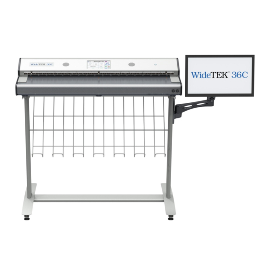
Page 20: Device Overview
Device Overview Picture 6: WideTEK 36C front view The main components of the WideTEK ® are: Upper unit. The upper unit contains the cameras and the paper transport. Touchscreen. The touchscreen shows all menus to set up and control the scanner On/Off button. -
Page 21: Monitor Connector
A.9.2 Monitor Connector To show previews of the scanned documents an external monitor can be connected to the WideTEK ® 36C. Two video connectors allow connecting the monitor either to the VGA connector or to the HDMI connector. Picture 8: VGA and HDMI connectors Please note: Due to the internal wiring only one external monitor is allowed to be connected to the scanner. -
Page 22: A.10 Connecting To The Power Source
A.10 Connecting to the Power Source Before connecting the scanner to the external power supply and the power supply to the electrical outlet, check the following items: Ensure the electrical outlet is in perfect condition and that it is properly grounded. Ensure that the electrical outlet is equipped with a fuse with the proper capacity. -
Page 23: Powering Up The Widetek ® 36C
Powering up the WideTEK ® A.10.1 The main power switch is found at the back of the scanner. Picture 7 shows the position of power supply connector and main power switch. After connecting the scanner to the external power supply, switch the main power switch to position I. -
Page 24: B Touchscreen Operation
Touchscreen Operation The WideTEK ® scanner can be controlled in two ways. • Via the integrated touchscreen. The functions of the touchscreen are described starting with chapter B.2. • Via a standard browser and the ScanWizard user interface. A short introduction of the functions of the integrated ScanWizard user interface starts in chapter C. -
Page 25: B.2 Start Screen Of The Kiosk User Interface
Start Screen of the Kiosk User Interface After touching the Scan2Net button the Viewer&Job Control screen is displayed on the touchscreen. Picture 11: Viewer & Job Control screen The touchscreen is structured in four sections, which allow operators to control and select various functions of the scanner. -
Page 26: B.2.1 Control Fields Of The Touchscreen
B.2.1 Control Fields of the Touchscreen By touching the buttons in section 2 each menu screen can be reached directly. The chapters B.3 to B.6 describe the functions of the menus in detail. Touch this button to start the scan sequence. Touch this button to return to the start screen from every other menu. -
Page 27: B.3 Touchscreen – Document Source
Touchscreen – Document Source The number of buttons and controllers in each screen can vary depending on the selected setup. The setup can be changed by the administrator in the Poweruser menu. The Document Source screen allows selecting from a wide range of scan parameters. Picture 12: Document Source screen, part 1 Picture 13 shows additional controllers of the Document Source screen. -
Page 28: B.3.1 Resolution
B.3.1 Resolution The Resolution setting allows selecting a resolution from a list of resolution values supported by the WideTEK ® scanner. Picture 14: List of Resolutions The list can be opened by touching the blue arrow symbol beside the currently selected value. -
Page 29: B.3.3 Scan Mode
B.3.3 Scan Mode The Scan Mode selector allows the user to select from two possible scan modes. Picture 16: Available Scan Modes High Quality Scans with reduced scanning speed but improved scanning quality. Fast Scans with normal speed, depending on the selected scan resolution. Manual Page 29... -
Page 30: B.3.4 Format
B.3.4 Format The Format button allows selecting the scan area size. Depending on the Document Mode selected, the available formats will vary. The bottom line of the button Format shows the current format setting. Picture 17: Selector for Format settings The following subchapters describe the available combinations of document mode and format. -
Page 31: B.3.4.2 Auto
B.3.4.2 Auto The complete scan area will be scanned. Picture 19: Format mode Auto The resulting image will be reduced to the document size. If the document is not exactly aligned horizontally, the resulting images will have the smallest possible black margin. The black margin depends on the size of rectangle which covers the complete document. -
Page 32: B.3.4.4 Din
B.3.4.4 DIN Picture 21: Format mode DIN When selecting DIN, an additional small window opens. It shows the available DIN (=ISO) document sizes as well as 25 inch and 36 inch width as scan area dimension. All formats are positioned symmetrically to the horizontal middle of the document input. B.3.4.5 ANSI Picture 22: Format mode ANSI When selecting ANSI, an additional small window opens. -
Page 33: B.3.5 Splitting Image
B.3.5 Splitting Image The button Splitting Image is used to select splitting the document scanned for the output images. Picture 23: Splitting Image Left: The selected format will be scanned completely. Only the left half of the selected format will be displayed. Right: The selected format will be scanned completely. -
Page 34: B.3.6 Exposure
B.3.6 Exposure The Exposure screen allows selecting the functions Black Cut and Auto. Fixed switches the function off. Picture 25: Exposure Modes When Black Cut or Auto is selected a numeric key pad opens. Picture 26: Numeric key pad to set threshold value Black Cut Sets the threshold for black. -
Page 35: B.3.7 Auto Density
B.3.7 Auto Density The Auto Density controller is used to set the scanner’s sensitivity for the automatic format detection. Default value: 60 Picture 27: Auto Density controller When scanning dark documents, the value should be reduced in small steps until the desired result is achieved. -
Page 36: B.4 Touchscreen – Image Quality
Touchscreen – Image Quality The Image Quality screen allows setting a wide range of image quality parameters. Picture 29: Image Quality, screen 1 In color mode Binary, the menu items will be extended with Invert and Despeckle. Picture 30: Image Quality 2 Page 36 Manual... -
Page 37: B.4.1 Color Mode
B.4.1 Color Mode By touching the selection arrow of the Color Mode section the list of available color modes opens. Picture 31: List of Color Modes Touch the title of the desired color mode to select the mode. The list closes subsequently. Picture 31 shows the available color modes. -
Page 38: B.4.2.2 Tiff
B.4.2.2 TIFF Picture 33: Submenu File Format TIFF With the TIFF file format, the compression method of the file can be selected with the TIFF Compression buttons. CCITT G4 Recommended with color mode “Binary”. JPEG Recommended for all other color modes. None Disables the data compression. -
Page 39: B.4.3 Brightness
B.4.3 Brightness Picture 34: Brightness slider The Brightness slider defines the resulting brightness in the image. Lower brightness values result in darker images, higher values result in brighter images. Values close to 0% or to 100% may result in unwanted artifacts. Move the slider indicator to the desired position to set the value. -
Page 40: B.4.7 Image Rotation
B.4.7 Image Rotation Picture 38: Image Rotation The value selected from the list defines the rotation of the image in a clockwise direction. The image will be rotated directly after scanning and before display B.4.8 Mirror Picture 39: Mirror This control mirrors the image along the selected mirror axis. Using this setting can be helpful if scanning transparencies from the back. -
Page 41: B.5 Touchscreen – Viewer&Job Control
Touchscreen – Viewer&Job Control The Viewer Control screen allows the operator to control and modify the image on the TFT flat screen. Picture 42: Viewer & Job Control screen The preview section (1) represents the TFT flat screen. The scanned image is displayed on the TFT flat screen and with reduced quality in the preview section right beside the controller elements. - Page 42 The controller is structured in three round elements (circles). The outer circle contains the keys to move the zoomed area across the image. The middle circle contains the keys to zoom in zoom out rotate the image in clockwise direction in steps of 90 degrees scale the image to the real size of the source document.
-
Page 43: B.5.1 Zonal Ocr
B.5.1 Zonal OCR The WideTEK ® offers a zonal OCR function. This function can be activated by the button positioned right below the preview section. Zonal OCR means, that only the marked area will be processed by the OCR function. Text and line feed will be found only. -
Page 44: Picture 46: Rectangle Defines The Area For Ocr Function
Touch the image at an arbitrary position. A red rectangle will be displayed. Picture 46: Rectangle defines the area for OCR function Exit: Press Exit to return to the former screen. CUT: Press the CUT button. The next screen will display the defined area more detailed. -
Page 45: Picture 48: Selected Area Magnified
Press CUT to separate the previously defined area from the complete image and to display it in detail. Picture 48: Selected area magnified The next screen shows the selected area magnified and allows again defining an area for the OCR process. Press CLR to return to the former screen and to repeat the definition of the OCR area. -
Page 46: B.5.2 Job Mode
B.5.2 Job Mode The bottom line of the Viewer & Job Control screen is different to the bottom line of the other screens. Picture 50: Bottom line with status The bottom line shows • the current scan mode status, • the button to switch the job mode between Single and Job mode •... -
Page 47: Picture 52: Disclaimer When Staring The Job Mode
When Job mode is selected, the contents of the touchscreen change. At first a disclaimer opens, which has to be accepted. Picture 52: Disclaimer when staring the Job mode After accepting the disclaimer, the Viewer&Job Control screen opens. It contains some additional control buttons above and below the preview section. Picture 53: Job mode start screen Manual Page 47... -
Page 48: B.5.2.1 Navigating Through The List Of Images
B.5.2.1 Navigating through the list of images The control buttons allow navigation through the list of scanned images and image handling while working in Job mode. The currently scanned image is always displayed in the preview section of the touchscreen and will be added as last image to the list displayed at the TFT flat screen. The control buttons allow moving upwards and/or downwards through the list of images to mark an image or... -
Page 49: B.5.2.2 Moving An Image To Another Position
B.5.2.2 Moving an image to another position Use the upwards / downwards buttons to mark the image to be moved. Press this button to select the image. The image now can be moved with the upwards / downwards buttons to the new position. Press this button again to place the image at the new position. -
Page 50: B.5.2.6 Finalizing The Job Mode
B.5.2.6 Finalizing the Job mode Before finalizing the Job mode the scanned images can be transferred to different destinations. Picture 55: Destination to finalize Job mode The destinations are identical to the destinations described in chapter B.6 and its subchapters. Before the Job mode will be finalized, a message is displayed at the touchscreen. -
Page 51: B.6 Touchscreen – Send To
Touchscreen – Send To This menu provides five output options in order to store the scanned images. Picture 57: "Send To" screen #1 Due to the dimension of the touchscreen, not all output options can be displayed at the same time. By using the scrollbar at the right side, the content of this menu can be moved. Move the scrollbar down to display the fifth output option on the touchscreen. -
Page 52: B.6.1 Changing A File Name Or Other Entries
B.6.1 Changing a file name or other entries In some of the option menus the file name can be changed. To change the file name, touch the respective line. The screen changes to an alphanumeric keyboard. Picture 59: Alphanumeric keyboard Use the arrow keys to position the cursor in the line. -
Page 53: B.6.2 Usb Options
B.6.2 USB Options Two USB connectors are available at the front of the scanner to connect suitable USB data carriers, for example USB sticks. Touching USB Options displays the directory of a connected USB data carrier. Picture 60: Directory of connected USB data carrier While the directory of the USB data carrier is displayed, the LED indicator of the respective connector is continuously illuminated. -
Page 54: B.6.3 Copy Options
B.6.3 Copy Options Touch Copy Options to switch to the screen with the preset copy option configurations. Three preset options can be stored and activated with the buttons Copy1 to Copy3. Picture 61: Parameters of Copy Options The parameters displayed in the above picture can only be changed from the Scan2Net® setup interface, user level Poweruser. -
Page 55: B.6.4 Ftp Options
B.6.4 FTP Options Touch FTP Options to switch to the screen with the preset FTP server configurations. Three preset FTP servers can be stored and activated with the buttons FTP 1 to FTP 3. Picture 63: Parameters of FTP Options From the touchscreen, only the entry for File Name can be changed. -
Page 56: B.6.5 Network Options
B.6.5 Network Options Touch Network Options to switch to the screen showing the preset network configurations. Three preset configurations can be stored and activated with the buttons Network 1 to Network 3. Picture 64: Parameters of Network Options From the touchscreen, only the entry for File Name can be changed. To change the entry, touch the respective line. -
Page 57: B.6.6 Mail Options
B.6.6 Mail Options Touch Mail Options to switch to the screen showing the preset email configurations. Three preset configurations can be stored and activated with the buttons Mail 1 to Mail 3. Picture 65: Parameters of Mail Options To change an entry, touch the respective line. From the touchscreen the values for •... -
Page 58: B.6.6.1 Transaction Modes
B.6.6.1 Transaction modes Two transaction modes are available for the mail transfer. The parameters for the transaction modes can be set from the Scan2Net setup interface. The mode, selected in the Scan2Net user interface, influences the process when a scanned image should be mailed. Automatic When pressing the button Mail image via SMTP at the touchscreen, the image will be sent to the address defined in the screen Mail Options... -
Page 59: C Software Operation
Software Operation Essentially, the scanner is a web server and comes with its own HTML based user interface, named ScanWizard. A basic requirement before working with the integrated ScanWizard user interface is to configure the browser as follows: • Force the browser to reload the page content every time directly from the scanner and not to load from the cache memory. -
Page 60: C.1 The Scanwizard User Interface
The ScanWizard User Interface After pressing the Launch Scan Application button the browser will show the ScanWizard interface. Picture 68: ScanWizard interface You can bookmark the address of the ScanWizard interface in your browser for easy access later. ScanWizard is a function rich software which allows the user configuring and operating the scanner easily without any additional software. -
Page 61: Picture 70: Online Help
These tool bars are described in detail in the online help function included in the ScanWizard interface, in the “Administration” menu, item “Online Help”. Picture 70: Online Help To exit the ScanWizard interface click on the main menu item “Administration” and then click on “Exit”. -
Page 62: C.2 Information
Information Click on the button Information in the Scan2Net® main menu (Picture 67) to get a short summary of the device parameters. The screen is helpful if technical support is necessary. It shows e.g. the exact device type, the installed firmware version as well as currently installed options. Click the button Back to return to the start screen. -
Page 63: D The Setup Level
The Setup Level The setup level is divided in three access levels. The access levels Poweruser and Admin are password protected. The User access level allows showing certain information about the system like power up time, remaining lamp life time or firmware version. Furthermore the access level User allows setting some basic parameters. -
Page 64: D.1 Access Level User
Access Level User Click the button User . This will open the below displayed screen. Picture 73: User screen The user screen is divided into two sections. The section Device Information shows some details of the scanner and gives general operation information. -
Page 65: D.1.1 Device Info Screen
D.1.1 Device Info Screen In the section Device Information click the button Device Info and the following list will be displayed (see Picture 74). Specific information can be reached by clicking the links below the headline Device Info. Picture 74: Device Info screen The table following the respective keyword shows the current status of the WideTEK ®... -
Page 66: Picture 75: Firmware Information
The most important information for users is the firmware version in the second table. Picture 75: Firmware information Click on the links to get other information may be of interest if a service technician is onsite or if the service hotline is called. To return to the USER screen (Picture 73), click the button Back to Main Menu or click on the “Return”... -
Page 67: D.1.2 Operation Info Screen
D.1.2 Operation Info Screen In the section Device Information the button Operation Info opens the following list. It shows various scan counters and elapsed time described in the following table. Picture 76: Operation Info screen The following table gives a brief description. Field Description Total Scan Count... -
Page 68: D.1.3 User Settings Screen
D.1.3 User Settings Screen In the section User Settings click the button User Settings and the following screen will be displayed. Picture 77: Start screen User Settings Power Saving screen will be displayed as start screen of the User Settings section. -
Page 69: D.1.3.1 Language Selector
D.1.3.1 Language Selector Use the function Language Selector to select the language for the setup interface. Picture 78: Language Selector of the setup menu Click at the selection arrow to show the list of available languages. Picture 79: List of languages Select by clicking the desired language from the list. -
Page 70: D.1.3.2 Power Saving
D.1.3.2 Power Saving Use the function Power Saving to set the timers for the standby modes. Three settings can be defined. Click on the link Power Saving. Picture 80: List of power down times The default settings for standby are 15 minutes; the default setting for screen saver is 10 minutes. -
Page 71: D.1.3.3 Volume
D.1.3.3 Volume Click the link Volume to set the loudspeakers volume of the scanner. Picture 81: Volume level A screen opens and shows a graphic to symbolize the volume. Click on the percentage value to change the volume level. The color of the graphic will change depending on the selected volume level. -
Page 72: D.1.3.4 Splitting Start
D.1.3.4 Splitting Start Page Click the button Splitting Start Page and select either the left page or the right page as start page. Picture 82: Splitting Start Page In some cases it is necessary to start splitting the documents image in reverse order, i.e. starting with the right side followed by the left side in the second step. -
Page 73: E Tests And Troubleshooting
Tests and Troubleshooting Troubleshooting Matrix Fields with a light blue background need the power user access level. All other fields are available to all users. Problem Possible cause Action Image is darker than The target used for white Go to the Adjustments function and expected. -
Page 74: F.1 Scanner Specifications
® Technical Data WideTEK Scanner Specifications Optical System Document width 38 inches / 965 mm Scan width 36 inches / 915 mm Maximum document thickness 0.05 inch / 1.5 mm Scan direction Face up Optical resolution 1200 x 600 dpi Scan resolution 1200 x 1200 dpi Pixel dimension... -
Page 75: F.2 Electrical Specifications
Electrical Specifications External Power Supply Voltage 100 – 240 V AC Frequency 47 – 63 Hz Inrush current 120 A max / 264 V AC Efficiency 85 % Operating temperature 5 to 40 °C / 41 to 104 °F Operating humidity 10 …... -
Page 76: F.3 Ambient Conditions
Ambient Conditions Operating temperature 5 to 40 °C / 40 to 105 °F Storage temperature 0° to 60 °C, 32° to 140 °F Relative humidity 20 to 80% (non-condensing) Noise level < 35 dB(A) (Operating) < 25 dB(A) (Standby) Dimensions and Weight Scanner outer dimensions 195 x 1100 x 410 mm (H x W x D) 7.7 x 43.3 x 16.1 inches... -
Page 77: F.5 Ce Declaration Of Conformity
Image Access GmbH Hatzfelder Strasse 161 – 163 42281 Wuppertal, Germany herewith declares that the Product: WideTEK 36C Scanner Model Designation: WT36C – XXX XXX represents the device version number and configuration details) Serial number: is in conformity with the following European standards and IEC directives:... - Page 78 EMC: EMC Directive 2004/108/EC as per EN 55022 :2006 + A1 :2007 EN 61000-3-2:2006 + A1 :2009 + A2 :2009 EN 61000-3-3 :2008 EN 55024 :1998 + A1:2001 + A2:2003 EN 61000-4-2:2009 EN 61000-4-3:2006 + A1 :2008 EN 61000-4-4:2004 + A1 :2010 EN 61000-4-5:2006 EN 61000-4-6:2009 EN 61000-4-11:2004...
-
Page 79: F.6 Fcc Declaration Of Conformity
Responsible party: Image Access GmbH Hatzfelder Strasse 161 – 163 42281 Wuppertal, Germany Product: WideTEK 36C Scanner Model Designation: WT36C – XXX XXX represents the device version number and configuration details) Serial number: This device complies with FCC, Part 15, Class B and ICES-003. - Page 80 For your notes Page 80 Manual...
Need help?
Do you have a question about the WideTek 36C and is the answer not in the manual?
Questions and answers