Image Access WideTEK 36 Setup Instructions
Hide thumbs
Also See for WideTEK 36:
- Operation manual (129 pages) ,
- Instruction manual (124 pages) ,
- Setup instructions (76 pages)
Table of Contents
Advertisement
Quick Links
Advertisement
Table of Contents

Related Manuals for Image Access WideTEK 36


Summary of Contents for Image Access WideTEK 36
- Page 1 WideTEK® 36/44/48 Setup Instructions English 12/2020...
-
Page 2: Table Of Contents
Contents Revision History ..................4 Information about the Instructions and the Manufacturer ....... 5 Keep Instructions with the Scanner ............5 Design Features in Text ................6 Design Features in Pictures..............7 Associated Documents ................7 Copyright ....................8 Contact Data of the Manufacturer in Germany ........8 Technical Support .................. - Page 3 Prepare for Setup ..................22 Connect the Power Supply ..............22 Establish the Network Connection ............23 Positioning the Scanner on the Optional Floor Stand ......23 Connect the Foot Switch ............... 23 Connect the Optional Monitor .............. 24 Connect the Optional Touchscreen ............25 Switch On the Scanner ................
-
Page 4: Revision History
Revision History Revision History Date Rev. Name Description of Reason of Change Change 09.12.2020 First draft First published version... -
Page 5: Information About The Instructions And The Manufacturer
Information about the Instructions and the Manufacturer Information about the Instructions and the Manufacturer These instructions show you how to safely prepare and perform the setup for the wide format scanners WideTEK® 36/44/48. The WideTEK® 36/44/48 scanners are hereinafter referred to as "Scanner". In these instructions, the start button is called "power button". -
Page 6: Design Features In Text
Information about the Instructions and the Manufacturer Design Features in Text Many text passages in these instructions have been formatted to indicate specific elements, as illustrated below: Normal text BUTTONS OF THE SCREEN PAGE "Menu names" ➢ Action steps • Enumeration of the first level Cross-references Tips contain additional information, such as special information to prepare for and perform the setup. -
Page 7: Design Features In Pictures
Information about the Instructions and the Manufacturer Design Features in Pictures Where a reference is made to elements in a legend or in the text, these are marked with a number (1). Associated Documents In addition to these instructions, other documents associated with the operation of the scanner include: •... -
Page 8: Copyright
© Image Access GmbH 2020 All rights reserved. Trademarks Scan2Net®, Scan2Pad®, Bookeye® and WideTEK® are registered trademarks of Image Access, all other trademarks are the property of their respective owners. Contact Data of the Manufacturer in Germany Image Access GmbH Hatzfelderstraße 161-163... -
Page 9: Safety
In this case, replace the power supply with a power supply of the same type. ➢ Do not use the scanner if it is visibly damaged. In this case, unplug the power cord from the wall outlet. Contact Image Access technical support, see section Technical Support starting at page 8. -
Page 10: Avoiding Property Damage And Malfunctions
Safety Avoid Burns ➢ Do not cover the existing openings in the scanner housing. They serve to ventilate. Covering the openings could cause overheating. ➢ Do not place the scanner in front of air conditioning units, which produce high heat. Avoid Fractures, Contusions and Bruises Incorrect installation of the cables can cause tripping. -
Page 11: Responsibility Of The Owner
Safety Responsibility of the Owner The scanner owner must ensure that only qualified personnel carry out the setup of the scanner. Staff Qualifications The staff that carries out the setup of the scanner must have knowledge in installing, connecting and putting computer accessories into operation. -
Page 12: Design Features Of Warning Notices
Safety Design Features of Warning Notices In these instructions, the following warning information can be found: WARNING Notices with the word WARNING warn about a dangerous situation that could lead to death or serious injuries. CAUTION Notices with the word CAUTION warn about a situation that could lead to light or medium-scale injuries. -
Page 13: Description
Description Description Purpose and Function The scanner is used for scanning images and documents. It is designed for use in enclosed spaces in the commercial sector. Intended use also includes observing and following all instructions in these instructions, especially the safety instructions. Any other use is considered to be improper and will void the warranty and liability claims. -
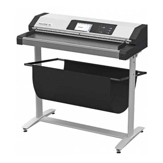
Page 14: Widetek® 36/44/48 Overview
Description WideTEK® 36/44/48 Overview Name Document transport Touchscreen USB port Keyboard buttons Main switch Transport guides Power button The WideTEK 44 scanner can be extended to a WideTEK 48 by purchasing a software option. - Page 15 Description Keyboard Buttons The keyboard of a WideTEK® 36/44/48-600 has three buttons with additional functions. Name Function Start Start job Scan Start scan Send Send job...
-
Page 16: Rear View
Description Rear View The following diagram shows the rear view of the scanner. Benennung Foot switch connector 24 Vdc connector for external power supply USB port Network connector DisplayPort connector Restore button... -
Page 17: Setup Menu Overview Screen
Description Setup Menu Overview Screen Name Buttons and parameters Menu name Display the online help Button to leave the setup menu to the start screen Serial number IP address Firmware version The display of the online help is only available when a second touchscreen is connected to the scanner. -
Page 18: Rating Plate
Description Rating Plate The rating plate is attached to the back of the scanner. The following figure shows the WideTEK® 36 rating plate. - Page 19 Description The following figure shows the WideTEK® 44 rating plate.
-
Page 20: Serial Number
Description The following figure shows the WideTEK® 48 rating plate. Serial Number The serial number of the scanner is located on the back of the device. Please have the serial number available for support requests. User Interfaces The scanner can be operated in five ways. •... -
Page 21: Device Location
Device Location Device Location Environment Choose a location that complies with the temperature and humidity specifications. Please allow • a minimum distance of 100 mm (4 inches) from any side walls, • a minimum distance of 50 mm (2 inches) from a back wall, •... -
Page 22: Prepare For Setup
Prepare for Setup Prepare for Setup Connect the Power Supply WARNING Risk of electric shock due to incorrect connection. ➢ Ensure that the power receptacle intended for the connection is properly grounded. ➢ Ensure that the power receptacle intended for the connection of the scanner is properly fused. -
Page 23: Establish The Network Connection
Prepare for Setup Establish the Network Connection CAUTION Incorrect routing of the connection cables can cause tripping. Fractures, contusions and bruises can be the result. ➢ Place the connecting cables so that no one can trip over them. To establish the network connection, proceed as follows: ➢... -
Page 24: Connect The Optional Monitor
Prepare for Setup ➢ Connect the plug of the foot switch to the connector socket for the foot switch, located on the back of the scanner. Connect the Optional Monitor CAUTION Incorrect routing of the connection cables can cause tripping. Fractures, contusions and bruises can be the result. -
Page 25: Connect The Optional Touchscreen
Prepare for Setup Connect the Optional Touchscreen CAUTION Incorrect routing of the connection cables can cause tripping. Fractures, contusions and bruises can be the result. ➢ Place the connecting cables so that no one can trip over them. To connect the optional touchscreen, proceed as follows: ➢... -
Page 26: Switch On The Scanner
Prepare for Setup Switch On the Scanner To switch on the scanner, proceed as follows: ➢ Press the MAIN SWITCH (1) to the "I" position. The following diagram shows the scanner model WideTEK® 36. The scanner is in standby mode. - Page 27 Prepare for Setup To start the scanner from standby mode, proceed as follows: ➢ Press the POWER button (2). The power button lights up in blue. The scanner performs a system test. After a short wait, the "Start screen" is displayed in English.
-
Page 28: Switch Off The Scanner
Prepare for Setup Switch Off the Scanner To switch the scanner to standby mode after performing the setup, proceed as follows: ➢ On the "Application Selection" screen tap on SHUTDOWN (1). Alternatively, you can also press, under 5 sec., the POWER button to do this. - Page 29 Prepare for Setup Alternatively, switch the scanner into the standby mode as follows: ➢ Press the blue illuminated power button and hold it for six seconds. The scanner shuts down. This process can take up to 40 seconds. The scanner is in standby mode. To switch off the scanner for longer periods, proceed as follows: ➢...
-
Page 30: Perform Setup
Perform Setup Perform Setup Setup Wizard The Setup Wizard is displayed on the touchscreen immediately after the startup process is completed. The Setup Wizard allows the user to perform the initial settings on the touchscreen of a Scan2Net scanner. After the Setup Wizard has been run through successfully, the scanner can be used immediately without any further necessary settings. - Page 31 Perform Setup All user interfaces of the Setup Wizard are described in the online help. To exit the Setup Wizard, you must deactivate it in the LAUNCH SCAN APPLICATION tile. To start the Setup Wizard after a reboot of the scanner, reactivate it in the SETUP DEVICE section of Scan2net.
-
Page 32: Performing The Adjustments
Performing the Adjustments Performing the Adjustments Activate the Setup Menu To activate the setup menu, you must log in on the scanner. Proceed as follows: ➢ Tap the GEAR SYMBOL (1). - Page 33 Performing the Adjustments The login window appears. ➢ In the login window, enter the login credentials. ➢ Tap on the "Username" input field. The screen keyboard is displayed. ➢ Enter the word "Poweruser". ➢ Tap on the "Password" input field. ➢...
- Page 34 Performing the Adjustments Setup Menu Overview Screen White Balance: Display the "White balance" submenu Display the "Camera Adjustment" and "Stitching" Camera Adjustment submenus Test Suite: Display the "Test Suite" submenu IP Address: Display the "IP Address" submenu WLAN Display the "WLAN" submenu User Settings: Display the "User Settings"...
-
Page 35: System Restore
System Restore System Restore Solid State Disk Software Failure The file system and the Linux operating system of a Scan2Net scanner are very robust and forgiving. The file system has the ability to repair itself, even if the system loses power during a disk write operation, a condition which will almost certainly corrupt any Windows, Android or MAC OS based computer. -
Page 36: System Restore To Factory Settings
System Restore System Restore to Factory Settings The restore procedure is a simple process: Step Action Shut down the scanner, either through the touch panel, through the currently used application or by pushing the POWER button on the scanner’s housing. If this does not work shut down the scanner by the MAIN SWITCH. -
Page 37: System Restore To User Settings
System Restore System Restore to User Settings Set Restore Point Step Action Open a tab in a web browser and enter the IP address assigned to the scanner. The Scan2Net window is displayed. Click on SETUP DEVICE, then click POWERUSER. Enter "Poweruser"... -
Page 38: Cleaning
Cleaning Cleaning To keep the scanner in good working condition, ensure that it is free of accumulated dust, ink, grease, and other contamination. The scanners are high resolution optical instruments with high quality glass parts. Since a higher quality scanner makes smaller dirt and dust particles more visible in the scans than a lower quality scanner, special care must be taken to keep all parts and especially all glass parts as clean as possible. -
Page 39: Technical Specifications
Technical Specifications Technical Specifications Optical System WideTEK® 36 Document Width 950 mm (37.4 inch) Scan Width 915 mm (36 inch) Scan Direction Face up Scanner Resolution 1200 × 1200 dpi (optionally 9600 × 9600 dpi interpolated) Optical Resolution 1200 × 600 dpi Pixel Dimension 9.3 ×... -
Page 40: Optical System Widetek® 44
Technical Specifications Optical System WideTEK® 44 Document Width 1270 mm (50 inch) Scan Width 1118 mm (44 inch) Scan Direction Face up Scanner Resolution 1200 × 1200 dpi (optionally 9600 × 9600 dpi interpolated) Optical Resolution 1200 × 600 dpi Pixel Dimension 9.3 ×... -
Page 41: Optical System Widetek® 48
Technical Specifications Optical System WideTEK® 48 Document Width 1270 mm (50 inch) Scan Width 1219 mm (48 inch) Scan Direction Face up Scanner Resolution 1200 × 1200 dpi (optionally 9600 × 9600 dpi interpolated) Optical Resolution 1200 × 600 dpi Pixel Dimension 9.3 ×... -
Page 42: Electrical Specifications
Technical Specifications Electrical Specifications External Power Supply Voltage 100–240 V AC Frequency 47–63 Hz Operating Temperature 5 to 40 °C (40 to 105 °F) Relative Humidity 20 to 80 % (non-condensing) ECO Standard CEC Level VI Scanner Voltage 24 V DC Current Max. -
Page 43: Dimensions And Weight Widetek® 36
Technical Specifications Dimensions and Weight WideTEK® 36 Scanner Outer Dimensions 228 x 1095 x 507 mm (H × W x D) (9 x 43 x 20 inch) Scanner Outer Dimensions (incl. 1070 x 1095 x 507 mm Floor Stand) (42 x 43 x 20 ich) (H ×... -
Page 44: Dimensions And Weight Widetek® 44/48
Technical Specifications Dimensions and Weight WideTEK® 44/48 Scanner Outer Dimensions 228 x 1425 x 507 mm (H x W x D) (9 x 56 x 20 inch) Scanner Outer Dimensions 1070 x 1425 x 507 mm (incl. Floor Stand) (42 x 56 x 20 inch) (H x W x D) Weight of Scanner 60 kg...
Need help?
Do you have a question about the WideTEK 36 and is the answer not in the manual?
Questions and answers