Table of Contents
Advertisement
Advertisement
Table of Contents

Related Manuals for Image Access bookeye 3


Summary of Contents for Image Access bookeye 3
-
Page 1: Operation Manual
Version R2 Operation Manual This device is compliant. -
Page 2: Table Of Contents, Part
File: BE3-R2_OperationManual-C4b.docx File: BE3-R2_OperationManual-C4b.docx... -
Page 3: Introduction
Dear Customer, We congratulate you on the acquisition of this innovative product from Image Access. We at Image Access are proud of the work we do; it is the result of our extremely high standards of production and stringent quality control. -
Page 4: General Information About Manuals
Image Access. All other trademarks are the property of their respective owners. Image Access reserves the right to change the described products, the specifications or documents at any time without prior notice. For the most recent version, always check our web site www.imageaccess.de... -
Page 5: Version History
Version History Version Published in Content/Changes/Supplements March 2008 First Edition. August 2008 Corrected values in chapter D.4. Minor correcting in some descriptions of details. January 2009 A note added concerning FCC regulations. October 2009 Valid with firmware version 5.22. Some detail improvements in the S2N user interface. February 2010 Some minor changes in text layout and numbering of the chapters. -
Page 6: Table Of Contents
Table of Contents Introduction -------------------------------------------------------------------------- 3 General Information about Manuals ----------------------------------------- 4 Version History --------------------------------------------------------------------- 5 A Hardware Operation -------------------------------------------------------- 11 Safety Notes .................... 11 A.1.1 Marking of Safety Notes A.1.2 Laser Safety Note Device Overview ..................12 A.2.1 Device Location A.2.1.1 Environment A.2.1.2... - Page 7 Table of Contents, part 2 B Software Operation --------------------------------------------------------- 23 The Integrated User Interface ..............23 B.1.1 The Main Screen B.1.2 The Options Screen B.1.2.1 Book Fold Options B.1.2.2 Fixed Focus Mode B.1.2.3 Embedded Meta Data B.1.3 The Properties Screen B.1.4 The Camera Screen B.1.5...
- Page 8 Table of Contents, part 3 C Tests and Troubleshooting ---------------------------------------------- 64 Troubleshooting Matrix ................64 D Technical Data ---------------------------------------------------------------- 66 Scanner Specifications ................66 Ambient Conditions .................. 66 Electrical Specifications ................67 Dimensions and Weight ................68 FCC Declaration of Conformity ..............69 CE Declaration of Conformity ..............
- Page 9 Table of Pictures Picture 1: Components of Bookeye® 3 scanner ...............12 Picture 2: Bookeye® 3 scanner back side view ..............14 Picture 3: Display before power up ..................16 Picture 4: Removing a Book Cradle Plate ................18 Picture 5: Book cradle Control Keys .................19 Picture 6: Book cradle at start ..................20 Picture 7: Book cradle at start with glass plate option ............20 Picture 8: Horizontal alignment check ................21...
- Page 10 Table of Pictures, part 2 Picture 27: Tool Tips ....................... 38 Picture 28: Status window ....................38 Picture 29: Format screen .................... 39 Picture 30: Rectangle dragged with mouse ..............40 Picture 31: "Zoom in" result ..................... 40 Picture 32:Output Option Show ..................41 Picture 33: Output Options in Scan Window ..............
-
Page 11: A Hardware Operation
Hardware Operation Safety Notes Read and ensure that you understand the safety notes. The safety notes have been written to ensure your protection and for your safety. All safety requirements of the following standards EN 60950-1:2006 UL 60950-1:2003-04-01 Ed.: 1 Rev: 2003/11/26 CAN/CSA C22.2 No. -
Page 12: Device Overview
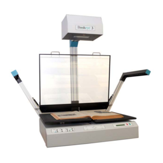
Device Overview Picture 1: Components of Bookeye® 3 scanner For a first look at the Bookeye® 3 scanner, some of the components have been identified in the above photo. These components are referenced in this operation manual. The Bookeye® 3 scanner main hardware elements are: —... -
Page 13: Device Location
A.2.1 Device Location A.2.1.1 Environment Choose a location that complies with the limits of temperature and humidity. Refer to chapter D.2 for detailed environmental specification. A.2.1.2 Ambient Light The location should have a controlled ambient light situation. Light scenarios to avoid are direct sunlight, spot light from light beams, light sources that cause sharp shadows on the scanning bed, high levels of ambient light and varying light conditions. -
Page 14: Table
A.2.1.3 Table Place the device on a flat and solid base, preferable a solid table. The load bearing capacity of the table must correspond to the device weight. The table should be build to hold at least three times the weight of the unit. Also it should not shake or move to avoid image distortions. -
Page 15: Connecting The Power Source
A.2.3 Connecting the Power Source The power connector and the main power switch are located at the right side of the back of the document bed. Important: Before connecting to the power source, check the following items: The wall outlet is in perfect condition and properly grounded. The power cable is not damaged in any way. -
Page 16: Starting The Bookeye® 3 Scanner
Starting the Bookeye® 3 scanner If the device has been used before and was constantly connected to power, the display will show the message: Standby and the green START field above the Start button is Press Start button illuminated. Picture 3: Display before power up If the device was previously disconnected from the main power supply, the standby message might not be visible. -
Page 17: Stopping The Bookeye® 3 Scanner
This procedure is followed by: Indicates, that the test for the motors and for the end position MECHANICS CHECK switches is running. The second line shows the IP address. 192.168.1.50 If the tests end successful, the display shows: Indicates the test of all remaining hardware components. HARDWARE CHECK 192.168.1.50 The second line shows the IP address. -
Page 18: Book Cradle
Book Cradle The motorized book cradle is safely and easily operated. Two driving elements on each side move the wooden cradles plates upwards. The plates are not connected to the stand-offs. If the book cradle is lowered and something blocks its way down, only the weight of the plate and eventually part of the weight of a book will squeeze the object. -
Page 19: Book Cradle Control Keys
A.4.2 Book Cradle Control Keys Picture 5: Book cradle Control Keys Operating one plate of the book cradle: Left cradle up/down and/or Right cradle up/down The control key on the outer side moves the corresponding cradle up and down independently of the other cradle plate. Operating both plates at the same time: Cradles up This... -
Page 20: Operating The Book Cradle
A.4.3 Operating the Book Cradle Note: Maximum load of each book cradle plate: 15 kg / 33 lbs First lower both cradles to their home position. Place a book on the right plate, open the book cover and raise the left cradle until it fully supports the left book cover. This is the reference position. -
Page 21: Picture 8: Horizontal Alignment Check
Note: Watch the small opening (see arrows in picture below) between the glass plate’s frame and the cradle. If the distance is equal on the upper and lower side, the glass plate is in the horizontal position. Picture 8: Horizontal alignment check Operation Manual Page 21... -
Page 22: Picture 9: Book Cradle In The Middle Of The Book
After the reference position is reached, use only the left and right compensation keys while advancing through the book. This will ensure that the distance of the book’s surface stays constant through the entire process and will therefore guarantee exactly the same resolution and size on all pages. Picture 9: Book cradle in the middle of the book Page 22 Operation Manual... -
Page 23: B Software Operation
Software Operation The Integrated User Interface Essentially, the scanner is a web server and comes with its own HTML based user interface. To access a Scan2Net scanner, any standard web browser can be utilized. Start your browser. Enter the IP address of the scanner. The default IP address of the scanner: 192.168.1.50 The following start screen of the integrated user interface will be displayed. -
Page 24: The Main Screen
B.1.1 The Main Screen After launching the scan application, the main screen of the integrated user interface will open. Picture 11: Main screen The main screen is structured in three parts. The menu bar of the large frame on the upper right part has five menu items: ... - Page 25 The seven control buttons in the lower part of the screen control the output modes. As default the output mode Show is selected. After clicking onto the button Preview or onto the button Scan Now a window opens and shows the image. When selecting Save the scanned image will not be displayed.
-
Page 26: The Options Screen
B.1.2 The Options Screen Options Picture 12: screen Document Mode Document Mode allows the user to select between different types of documents: Flat Mode the document is treated as flat, i.e. with a fixed focus setting, regardless of the actual shape of the document. This mode avoids out of focus problems when scanning three dimensional objects that cannot be described as folders or books. - Page 27 Scan Mode Scan Mode allows the user to select between High Quality with a reduced scanning speed or Fast with normal speed. Image Rotation Image Rotation can be any degree of rotation out of 90°, 180°, 270° or none. The angle is defined in the clockwise direction.
-
Page 28: Book Fold Options
B.1.2.1 Book Fold Options Clicking on (Options) opens an additional window. It allows to set the value for the margins, the left and the right center position as well as the threshold value. The unit of measurement is “mil”. This unit of measurement is defined as 1000 mil = 1 inch. -
Page 29: Embedded Meta Data
B.1.2.3 Embedded Meta Data This function is used in conjunction with the file formats JPEG, TIFF or PDF. It will allow the operator to include a set of XMP/RDF compliant document metadata in the file header. Select Yes or No. Go to (Options) to define a set of XMP/RDF compliant metadata. -
Page 30: The Properties Screen
B.1.3 The Properties Screen Properties Picture 16: screen Color Mode Color Mode control allows the user to select from a list the desired color modes. Available are 24bit Color and 8bit Color as well as Grayscale, Binary and Photo. File Format File Format control defines the file format that is used to store a scanned image. -
Page 31: Picture 17: X- And Y Offset Definition
Format Format control selects between various standard paper formats. If Auto is selected, the scanner scans the maximum format and then crops the document to its real size. This function is highly advanced and works with default values most of the time. The Auto function can also be statically configured with the two sliders Auto Density Additional Margin... -
Page 32: The Camera Screen
B.1.4 The Camera Screen Camera Picture 18: screen In this screen all parameters concerning the camera will be set. Some interdependencies exist between controls displayed in this screen and settings in other screens. The Despeckle control e.g. is only displayed if the color mode Binary is selected. -
Page 33: Picture 19: Dpi Mode Fixed
Picture 19: DPI mode Fixed DPI Mode If the button DPI Mode is at Fixed, the resolution can be selected out of a drop down list in the Resolution field. Resolution The values for Resolution can be 150, 200, 300, 400 and 600 DPI and also true DPI. true DPI is used if the scanner’s real resolution, depending on thickness of the document as well as the position of the book cradles, should be used. -
Page 34: Picture 20: Dpi Mode Flexible
Picture 20: DPI mode Flexible DPI Mode If the button DPI Mode is set to Flexible, the resolution can be selected out of a drop down list right to the Resolution field. This value can be manually overridden. Enter the desired resolution in the field left from the drop down list field. -
Page 35: Picture 21: Black Threshold Slider
Image Sharpness Image Sharpness slider invokes an advanced algorithm which sharpens the image according to the local content of a given area. Exposure Exposure function sets the threshold value for the black cut function or for the auto exposure function. Picture 21: Black Threshold slider No disables the exposure function. -
Page 36: Picture 22: Gamma Slider With Preselection Buttons
Gamma Gamma slider does the gamma correction directly inside the camera electronics. Picture 22: Gamma slider with preselection buttons Three typical values are predefined on the Preselection buttons. Color Gain Color Gain drop down list changes the gain on a specific channel. This function is used to eliminate any color shift or tints from the background. -
Page 37: The Settings Screen
B.1.5 The Settings Screen Settings Picture 24: screen This screen allows the user to set some secondary parameters. Language Selector Language Selector offers a drop down list of languages for the scanner’s user interface. Currently available languages are polski, français, russian, deutsch and english. -
Page 38: Picture 26: Skin Selector
Skin Selector Skin Selector offers different surfaces (skins) for the user interface. Currently available surfaces are modern and application, metal and classic, classic-green and classic- light. Other skins can be designed and integrated by the user. Picture 26: Skin Selector Tool Tips Tool Tips can be activated to inform... -
Page 39: The Format Screen
B.1.6 The Format Screen Format Picture 29: screen When selecting this screen the image scanned and displayed at last is shown. The dimension of the image depends on the selected format in the Properties screen. The Preview (Maximum) button allows to rescans the complete document area. -
Page 40: Picture 30: Rectangle Dragged With Mouse
To select a specific area of the image, click with the mouse in the preview area and drag a rectangle. Dragging with the mouse the rectangle starts in the upper left corner and ends in the lower right corner. Click the Zoom in button to display the selected area of the image in detail. ... -
Page 41: Output Options
B.1.7 Output Options There are various output options available on a Scan2Net scanner. In most cases, the button Show is activated. Picture 32:Output Option Show A scan will open a new browser window and display the image on the screen. The output options described in this chapter are accessible via the above menu but are also present in the upper part of each scanned image. -
Page 42: Output Option Save
B.1.7.1 Output Option Save This output option scans to the local disk drive. After the scan is performed, a window opens and the default file name is shown. The user can select local and network drives for the save location and can also change the file name before it is actually stored. -
Page 43: Output Option Print
B.1.7.2 Output Option Print This output option prints to the locally available printers. After the scan is executed, the standard windows printer interface is opened. The user can select one of the locally available printers. Picture 36: Output Option Print Picture 37: Available List of Printers for Option Print Operation Manual Page 43... -
Page 44: Output Option Copy
B.1.7.3 Output Option Copy This output option prints directly to a previously installed network printer. The Option is used to configure the remotely connected printer. Picture 38: Output Option Copy Remote Printer Description Printer Preset Choose a printer configuration out of five possible sets of parameters. - Page 45 Remote Printer Description Login Enter the login for the printer if Server Authentication is set to Yes. (with SMB Printer Queue only) Password Enter the password for the printer if Server Authentication is set to Yes. Data Format Choose the data format of the remote printer. Selectable are Postscript, Postscript with framing HP/PJL communication and HP DesignJet (HP/RTL) compliant printers.
-
Page 46: Output Option Ftp Upload
B.1.7.4 Output Option FTP Upload The scanner can directly scan to a FTP server. Picture 39: Output Option FTP Upload Option key is used to configure the FTP interface. A configuration window will pop FTP Upload Description Address Enter the IP address of the remote FTP server. Port (21) Enter the IP port of the remote FTP server. - Page 47 FTP Upload Description Password Enter the password for the login at the remote FTP server. The password is stored using encryption. Upload Path Enter the upload path at the remote FTP server, starting with / (root). Click on the icon, to browse the directory structure of the remote FTP server.
-
Page 48: Output Option Mail
B.1.7.5 Output Option Mail The scanner can directly e-mail each scan. Picture 40: Output Option Mail Option key is used to configure the mail interface. A configuration window will pop Mail Upload Description Transaction mode Choose if all scanned documents will be send to the same receiver (automatic batch mode) or if the scanner should ask after every scan (interactive). - Page 49 Mail Upload Description Login Enter the user name for authentication at the outgoing mail server. Password Enter the password for authentication at the outgoing mail server. The password is stored using encryption. Protocol Choose the connection protocol. SMTP is the most common protocol.
-
Page 50: Output Option Network
B.1.7.6 Output Option Network SMB is a network protocol which is used by Microsoft windows based networks. Picture 41: Output Option Network Option key is used to configure the SMB Upload interface. A configuration window will pop up. SMB Configuration Description Port (139) Enter the IP port of the SMB network communication. -
Page 51: The Setup Screen
The Setup Screen Although most settings on the system level can be performed only in the Poweruser access level, some user defined settings are available on the start screen. The User access level also allows showing certain information about the system like power up time, remaining lamp life time or firmware version. -
Page 52: User Login Level
B.2.1 USER Login Level Click the button User . Picture 43: User screen The user screen is divided into two sections. Information The section Information shows some details of the scanner and gives a general operation information. User Settings The section User Settings allows the user to define some basic parameters of the scanner. -
Page 53: Device Info
B.2.1.1 Device Info In the section Information click the button Device Info and the following list will be displayed. Specific information can be reached by clicking the links below the headline Device Info or by scrolling through the list. Picture 44: Device Info screen The tables following the keyword show the current status of the Bookeye®... -
Page 54: Operation Info
B.2.1.2 Operation Info In the section Information the button Operation Info opens the following list. It shows various scan counters and elapsed time described in the following table. Picture 45: Operation Info screen Field Description Total Scan Count The total number of scans performed since the scanner left the factory. -
Page 55: User Settings
B.2.1.3 User Settings In the section User Settings click the button User Settings and the following screen will be displayed. Picture 46: User Settings screen The Bookeye® 3 scanner is Energy Star compliant. In stand-by mode it consumes only 5W of power. The Energy Star guidelines require the default time until the device goes into standby to be 15 minutes. -
Page 56: Picture 47: Volume Level
B.2.1.3.2 Volume Click the button Volume to set the loudspeakers volume of the scanner. Picture 47: Volume level A screen opens and shows a graphic to symbolize the volume. Click on the percentage value to change the volume level. The color of the graphic will change depending on the selected volume level. -
Page 57: Picture 48: Foot Pedal Settings
B.2.1.3.3 Foot Pedal Click the button Foot Pedal to define the action for each pedal. Picture 48: Foot pedal settings The scanner has two connectors on its back to connect foot pedals. For each foot pedal a specific action can be defined. Click the button Foot Pedal. -
Page 58: Picture 49: Splitting Start Page
B.2.1.3.4 Splitting Start Page Defines the start page when page splitting is selected. Picture 49: Splitting Start Page In some languages, books are printed from right to left. In these cases, it can be desirable to start the page splitting in the reverse order, i.e. starting with the right side followed by the left side in the second step. -
Page 59: Laser Guided Document Type Detection
Laser guided Document Type Detection This chapter is important to understand because it describes the most common scanning problems and their cure. The Bookeye® 3 scanner has an auto focus system that actually stays in focus as the scanner sweeps from left to right over the scanning area. To achieve this, the pre scan must be able to capture the heights profile of the document. -
Page 60: Picture 51: Holding Down A Book
— The area where the laser line covers the outer edges of the document is the only area, where the optional thumb removal function will work. The user should hold down the book only in these areas. Picture 51: Holding down a book —... -
Page 61: Scanning In Fixed Focus Mode
B.3.2 Scanning in Fixed Focus Mode This is the simplest scanning mode. The focus is fixed to a known position that the user can change. See chapter 0 for detailed description. If the glass plate option is installed, this value is overridden and replaced with the auto- focus value measured during the installation of the glass plate option. -
Page 62: Scanning In Folder Mode
B.3.4 Scanning in Folder Mode This mode is similar to the flat mode, but it treats both sides of the document bed independently. The scanner performs a pre-scan and measures the heights of the document on the left side and the right side. Picture 52: Scanning in folder mode If the measurement does not produce any meaningful results the keyboard will play the sound “Attention”... -
Page 63: Scanning In Book Mode
B.3.5 Scanning in Book Mode The scanner measures the height profile as it advances over the scanning bed in the pre-scan. The profile of a book has some typical characteristics that the scanner attempts to find. One of these is the book fold, which the scanner will find and use later for further compensation. -
Page 64: C Tests And Troubleshooting
Tests and Troubleshooting Troubleshooting Matrix Fields with light blue background need the power user access level. All other fields are available to all users. Problem Possible cause Action Green start button does not No power Check main outlet, power cord, power- light up. - Page 65 Problem Possible cause Action Image has unevenly spaced The electronics gear is out Exercise the Scan Start procedure. vertical stripes or streaks. of sync. Image has evenly spaced 50/60Hz interference from Change position, dim or shut off some vertical stripes or streaks. fluorescent ceiling lights.
-
Page 66: D Technical Data
Technical Data Scanner Specifications Scan Area Maximum Scan Area [pixel] 7560 x 6442 pixels Maximum Scan Area [mm] 640 x 520 mm Optical Resolution 400 x 600 dpi Resolution 150 – 600 dpi Auto focus range 120 mm Max. document thickness 120 mm / 90 mm (without / with glass plate) Luminosity Scanning... -
Page 67: D.3 Electrical Specifications
Electrical Specifications This device is Energy Star compliant. Voltage 110–240 VAC Frequency 50/60 Hz Power Consumption Standby 0.1 W Self-test mode 135 W Stand-by, operational, lamps off 90 W Operating 260 W Pre-Scan 130 W Moving the book cradle (lamps off) Both plates simultaneously 128 W Single plate... -
Page 68: D.4 Dimensions And Weight
Dimensions and Weight Scanner outer dimensions (without lamps) 1065 x 670 x 700 mm (H x W x D) 41.9 x 26.4 x 27.6 inch Scanner outer dimensions (lamps attached) 1065 x 1270 x 700 mm (H x W x D) 41.9 x 50 x 27.6 inch Total weight of scanner, ready to use 68,5 kg / 150.7 lbs... -
Page 69: D.5 Fcc Declaration Of Conformity
FCC Declaration of Conformity Responsible party: Image Access GmbH Hatzfelder Strasse 161 – 163 42281 Wuppertal, Germany Product: Bookeye Planetary Scanners Model Designation: BE3-AAA-BCd-XXX with AAA = SCL or SGS or CGS B = R or N C = 1 or 2 or 3 (... -
Page 70: D.6 Ce Declaration Of Conformity
CE Declaration of Conformity The undersigned, representing the manufacturer: Image Access GmbH Hatzfelder Strasse 161 – 163 42281 Wuppertal, Germany herewith declares that the Product: Bookeye Planetary Scanners Model Designation: BE3-AAA-BCd-XXX with AAA = SCL or SGS or CGS B = R or N... - Page 71 EMC: EMC Directive 2004/108/EEC as per EN 55022 :2006, Class A with EN 61000-3-2:2006 EN 61000-3-3 :1995 + A1:2001 + A2:2005 EN 55024 :1998 + A1:2001 + A2:2003 EN 61000-4-2:1995 + A1:1998 + A2:2001 EN 61000-4-3:2006 EN 61000-4-4:2004 EN 61000-4-5:2006 EN 61000-4-6:1996 + A1:2001 EN 61000-4-11:2004 Wuppertal, 25.02.2008...
- Page 72 For your notes Page 72 Operation Manual...
Need help?
Do you have a question about the bookeye 3 and is the answer not in the manual?
Questions and answers