Table of Contents
Advertisement
Quick Links
Advertisement
Table of Contents

Subscribe to Our Youtube Channel
Related Manuals for Image Access WideTEK 36 DS


Summary of Contents for Image Access WideTEK 36 DS
- Page 1 Manual This device is compliant.
- Page 2 File: WT36DS_OperationManual_B2.docx...
- Page 3 Image Access. All other trademarks are the property of their respective owners. Image Access reserves the right to change the described products, the specifications or documents at any time without prior notice. For the most recent version, always check our web site www.imageaccess.de...
-
Page 4: Introduction
Dear Customer, We congratulate you on the acquisition of this innovative product from Image Access. We at Image Access are proud of the work we do; it is the result of our extremely high standards of production and stringent quality control. -
Page 5: About This Manual
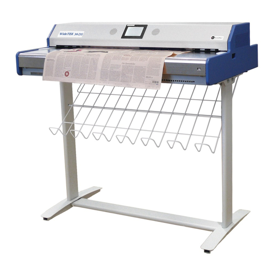
Remember that this device is a precise optical instrument and should be handled accordingly. Note: For the WideTEK 36 DS an appropriate floor stand is available. It is recommended to always use the WideTEK 36 DS in combination with the floor stand. -
Page 6: Version History
Version History Version Published in Content/Changes/Supplements February 2010 Preliminary release version. September 2010 First release. March 2011 Dimension of transport box updated. April 2012 Output Option Web added. Following chapters renumbered. February 2013 Update Copyright note August 2013 New logo introduced Page 6 Manual... -
Page 7: Table Of Contents
Content on Delivery .................... 18 Connecting to the Power Source ................ 19 A.9.1 Connectors on the Scanner A.10 Powering up the WideTEK 36 DS ..............21 A.10.1 Starting the WideTEK 36 DS from Stand-By Mode A.10.2 Turning-off the WideTEK 36 DS A.10.3... - Page 8 Table of Content, part 2 Self Test Mode ....................25 B.3.1 IP Address B.3.2 White Balance B.3.3 Lamp On / Off B.3.4 Exit Selftest B.3.5 Touch Adjust B.3.6 Touch Test B.3.7 Stitch Test B.3.8 EMV Test B.3.9 Sensor Test B.3.10 Shutdown Scanner Start Menu Screen .....................
- Page 9 Table of Content, part 3 C Software ------------------------------------------------------------------------ 56 The Integrated User Interface................56 The Main Screen ....................57 C.2.1 The Options Screen C.2.2 The Properties Screen C.2.3 The Camera Screen C.2.3.1 Threshold Dynamic / Threshold Fixed C.2.3.2 Despeckle C.2.4 The Settings Screen C.2.5 The Format Screen...
-
Page 10: Technical Data
Table of Content, part 4 D Tests and Troubleshooting --------------------------------------------- 108 Troubleshooting Matrix ..................108 Error Codes ..................... 109 Warnings ......................111 Information ...................... 111 E Technical Data --------------------------------------------------------------- 112 Scanner Specifications ..................112 Ambient Conditions ..................113 Electrical Specifications ................... 113 Dimensions and Weight ................... -
Page 11: Manual Page
Table of Pictures Picture 1: Minimum distances to the scanner ..............16 Picture 2: Transport box opened ..................18 Picture 3: Connectors at WideTEK 36 DS ................20 Picture 4: Start menu screen ....................21 Picture 5: Touch panel while shut down in progress ............22 Picture 6: Keyboard with capital letters ................24... - Page 12 Table of Pictures, part 2 Picture 34: Format control 2 .................... 44 Picture 35: Format Control 3 ................... 45 Picture 36: File Control ....................46 Picture 37: Transport control ................... 49 Picture 38: List of available jobs ..................51 Picture 39: Keyboard of input screen ................51 Picture 40: Creating a job ....................
-
Page 13: Manual Page
Table of Pictures, part 3 Picture 67: Rectangle dragged with mouse ..............72 Picture 68: "Zoom in" result ....................72 Picture 69: List of available clip size formats ..............72 Picture 70: Output options bar ..................73 Picture 71: Output Option Save ..................74 Picture 72: Example for file name ..................74 Picture 73: Output Option Show ..................75 Picture 74: Output Options in Scan Window ..............75 Picture 75: Output Option Multipage ................76... -
Page 14: A Hardware
(Standard for Canada) EN 60950-1, Safety for Information Technology Equipment (European standard) General Notice This manual describes the functions of a complete equipped WideTEK 36 DS scanner. If your device is not equipped with all features, deviations are possible. Page 14... -
Page 15: Safety Precautions
13. Always turn the power off and unplug the power cord from the wall receptacle before cleaning the scanner. 14. When cleaning, only use Image Access-approved cleaners. Do not use any type of solutions, abrasives, or acids such as acetone, benzene, kerosene, mineral spirits, ammonia, or nitric acid. -
Page 16: Device Location
Do not operate the scanner in an area that has poor air circulation, and/or that is non- ventilated. Place the WideTEK 36 DS on a flat and solid base. The load bearing capacity of the base must correspond to the device weight. -
Page 17: Maintenance
Ensure that no liquids will penetrate into the device housing. A.6.1 Touchscreen Before cleaning the touchscreen, switch the WideTEK 36 DS off and set the main power switch to position 0. The touchscreen can be cleaned with a micro fiber cloth. -
Page 18: Content On Delivery
Content on Delivery The scanner is delivered in a wooden transport box. The transport box also contains the disassembled floor stand in a separate cardboard box and the paper catch basket. Picture 2: Transport box opened 1: Paper catch basket 2: Folder with CSTT-1 reference targets and IT8 sheet. -
Page 19: Connecting To The Power Source
Connecting to the Power Source Before connecting the scanner to the electrical outlet check the following items: Ensure the electrical outlet is in perfect condition and that it is properly grounded. Ensure that the electrical outlet is equipped with a fuse with the proper capacity. -
Page 20: Connectors On The Scanner
The connectors are positioned at the left side of the housing, as seen from the operators view (i.e. from the front of the scanner). Picture 3: Connectors at WideTEK 36 DS 1: Secondary network cable connector (downside camera box) 2: Foot pedal connector... -
Page 21: Powering Up The Widetek 36 Ds
Starting the WideTEK 36 DS from Stand-By Mode When the WideTEK 36 DS is in stand-by mode, it can be started by tapping the touch panel on any arbitrary position. The touch panel lights up and a rotating hourglass indicate that the start sequence is running. -
Page 22: Turning-Off The Widetek 36 Ds
WideTEK 36 DS is in stand-by mode and before the scanner is disconnected from the electrical outlet. To turn the WideTEK 36 DS off, press and hold the Stop button on the touch panel. While the Stop button is held, a counter in the button shows the remaining time until the WideTEK 36 DS is powered down. -
Page 23: B Touch Panel Operation
It shows an easy-to-use menu and helps the user to control all scanner parameters with the touch of a finger. When the WideTEK 36 DS is powered up by using the main power switch, the touch panel is illuminated in a dimmed mode and shows the stand-by screen. The stand-by screen shows the Image Access logo and the blinking message Touch screen to power up. -
Page 24: How To Enter Or Change Values
How to Enter or Change Values To enter new values or change existing values, the corresponding field or line in the screen must be touched. If a parameter requires an alphanumeric value, the touch panel display changes and shows a keyboard where text and numeric values can be entered. Moves cursor to the left. -
Page 25: B.3 Self Test Mode
Self Test Mode While the start sequence is running the WideTEK 36 DS can be switched to Self Test mode. Tapping on the touch panel at least three times starts the setup mode. After the start sequence is finished, the touch panel shows the Self Test 1 screen. -
Page 26: B.3.1 Ip Address
B.3.1 IP Address Touch the control field IP Address. The touch panel changes to a mask where the values • the IP address for the front camera (Address F.), • the IP address for the back camera (Address B.), • Gateway, •... -
Page 27: Manual Page
Touch on the line to be changed, e.g. the Address line. The touch panel shows: Picture 12: Numeric key pad Enter the new values. The < and > keys move the cursor, the X key deletes the number at the cursor position. To finalize the input tap on the checkmark key. -
Page 28: B.3.2 White Balance
B.3.2 White Balance Touch the White Balance button to switch to the next screen. Now insert the control sheet. It must be transported forward and reverse. Then touch the Cont. button. The control sheet will be pulled in and the measurement starts. -
Page 29: B.3.5 Touch Adjust
B.3.5 Touch Adjust This function defines the dimension of the writing area of the touch panel. The first step after selecting this function must be done very quickly to activate the adjustment procedure. Note: It is recommended to read first, then act. It is recommended to use for the following adjustment steps an appropriate pen, e.g. -
Page 30: B.3.7 Stitch Test
B.3.7 Stitch Test Picture 17: Stitch Test screen Press the Stitch Test button to start the stitch test. This starts a program in which you can see an automatically updated view of the stitching indicators for each camera. The measurement will be executed continuously, once every second. The cameras left, middle and right are identified as the left, middle and right cameras when looking at the scanner from the operator’s view (i.e. -
Page 31: B.3.9 Sensor Test
No paper detected by the sensors. Paper detected at input side (PWT). Paper detected at input side (PWT) and at output side (POT). Picture 18: Sensor status B.3.10 Shutdown Scanner Switches the WideTEK 36 DS scanner off. Manual Page 31... -
Page 32: B.4 Start Menu Screen
Start Menu Screen Picture 19: Start menu screen When all initial tests are finished, the display shows the start menu screen. At the top of the start menu, the main controls to start a scan sequence and to stop the current action are displayed. -
Page 33: B.4.1 Output Control Screen
B.4.1.1 Output Control 1 Picture 21: Output Control 1 B.4.1.1.1 Viewer Control An external monitor can be connected to the WideTEK 36 DS to show the scanned image directly. Touching the Viewer Control button starts the Zoom/Move Control mode. When this mode is active, the displayed image on the screen can be moved and the zoom factor can be changed. -
Page 34: Picture 23: E-Mail Address Parameters
B.4.1.1.2 Email Address This menu item enables the user to send the scanned image to any arbitrary e-mail address. Stores all parameters. Erases all changes. Picture 23: E-mail address parameters How to enter an E-mail address Tap on the line of the e-mail address. The screen changes to input mode as shown in Picture 6 and Picture 7. -
Page 35: Picture 24: Ftp Server 1
B.4.1.1.3 FTP Server The Ftp Server button enables the user to enter all necessary information for data transfer to a dedicated FTP server. The parameters are entered in two screens named Ftp Server 1 and Ftp Server 2. Ftp Server 1 This screen contains the server IP address and the port, the user name and the password for the server access. -
Page 36: Picture 26: Network Parameters
B.4.1.1.4 Windows Network Allows the user to • define the network path where the image should be stored, • the define the authentication method, • define the user name, • define the password, • define the filename Picture 26: Network parameters To store all entries of this menu touch the button How to enter a Network Address Picture 27: Input a Network Address... -
Page 37: B.4.1.2 Output Control 2
B.4.1.2 Output Control 2 Picture 28: Output Control 2 B.4.1.2.1 Sound Control The menu item Sound Control allows the user to link sounds to system events. Picture 29: System events and sound files To select a system event, touch the scroll bar in the left window or the up/down arrows. The currently selected sound file associated with this system event will be displayed in the right window. -
Page 38: B.4.2 Image Control Screen
B.4.2 Image Control Screen The parameters are set in the screens named Image Control 1 and Image Control 2. B.4.2.1 Image Control 1 Picture 30: Image Control 1 In general: • Tap the + or – to change the values in steps of one. •... - Page 39 B.4.2.1.4 Sharpness An automatic sharpening algorithm is applied to the image before any other operation is performed. The value zero disables the function. Very high values may produce artifacts, depending on the document characteristics. B.4.2.1.5 Resolution This parameter defines the scanner’s resolution. This button offers three ways to set the desired value: •...
-
Page 40: B.4.2.2 Image Control 2
B.4.2.2 Image Control 2 Picture 31: Image Control 2 Note: Depending on the selected color mode, some buttons may not be displayed. B.4.2.2.1 Threshold (only in Binary mode) Defines the contrast control mode. Available modes are Fixed and Auto. Fixed: The contrast is fixed to defined value. - Page 41 B.4.2.2.4 Stitching Select the stitching method, which is used to merge the image data to one image. Fixed: Merges the image data at a specified offset area, resulting from the camera calibration. Adapt.1D: Recommended for all documents with good paper quality and plain surface. It results in high throughput with large-sized documents.
-
Page 42: B.4.2.3 Image Control 3
B.4.2.3 Image Control 3 Picture 32: Image Control 3 Note: Only in the color modes 24b color, 8b color, and Grayscale. B.4.2.3.1 Exposure This setting defines the exposure correction mode. Available are Black Cut, Auto and Fixed. Black cut: All color values in the image which are below the threshold for black are displayed as black. -
Page 43: B.4.3 Format Control Screen
B.4.3 Format Control Screen The parameters are set in three screens; Format Control 1 to Format Control 3. To switch between the Format Control screens use B.4.3.1 Format Control 1 Picture 33: Format Control 1 B.4.3.1.1 Format This control specifies the format of the document. In most cases the setting Auto should be selected. -
Page 44: B.4.3.2 Format Control 2
B.4.3.2 Format Control 2 Picture 34: Format control 2 B.4.3.2.1 Auto margin The Auto margin control detects the edges of a document and cuts it out of the scanned image. If the value (in pixels) is negative, the resulting image will be smaller than the document. If the value is positive some of the background will remain in the scanned image. -
Page 45: B.4.3.3 Format Control 3
B.4.3.3 Format Control 3 Picture 35: Format Control 3 In general: The units can have various units of measurement. Only positive values can be entered. B.4.3.3.1 Top edge This setting defines a zone on the document that is not scanned. The zone starts from the top of the document to the value specified via this function. -
Page 46: B.4.4 File Control Screen
B.4.4 File Control Screen Picture 36: File Control The control File format specifies the file format of the image file. Depending on the selected file format, the number and the content of the controls in this screen can vary. The list of formats includes JPEG, TIFF, PNM, and PDF (if the option is installed). B.4.4.1 JPEG When selecting the file format JPEG the functions of the controls are:... -
Page 47: B.4.4.2 Tiff
B.4.4.2 TIFF When selecting the file format TIFF the functions of the controls are: Note: Depending on the selected color mode in Image Control the available compression methods vary. • TIFF compr. None: Available with all color modes. JPEG: Available with “24b color” and “Grayscale”. Additionally the controls “JPEG quality”... -
Page 48: B.4.4.4 Pdf
B.4.4.4 When selecting the file format PDF the functions of the controls are: • JPEG quality: Defines the compression rate. The JPEG quality level is defined with this control. A higher percentage gives better quality but the file size will increase. A lower factor will show some artifacts in the image but the file size will be reduced. -
Page 49: B.4.5 Transport Control Screen
B.4.5 Transport Control Screen Picture 37: Transport control B.4.5.1 Start button This setting defines the start method of the scanner. • Direct The scan starts when the scanner receives the start command from the application. • Wait The scan will only start if the start button in the touch panel is pressed. The start button can also be a foot pedal. -
Page 50: B.4.5.2 Transport
B.4.5.2 Transport This setting defines the transport speed of the scanner. • Normal Standard transport speed depending on the selected scan resolution, i.e. the higher the scan resolution, the slower the transport speed. • Slow The scanning speed is reduced and the paper handling is relaxed, in order to make the handling of sensitive documents safer. -
Page 51: B.4.6 Job
B.4.6 Picture 38: List of available jobs The control Job allows the user to create and store specific settings of the scanner. This is useful if the scanner is operated by several users with different settings for document size, resolution or other parameters. B.4.6.1 Creating a Job Creating a “job”... -
Page 52: Picture 40: Creating A Job
Tap on Create to save the job. Tap on with password to save the job password protected. Tap on Cancel to cancel the procedure. Picture 40: Creating a job If a password should be used, tapping on the button with password opens a screen as shown in the picture on the left. -
Page 53: B.4.6.2 Selecting A Job
B.4.6.2 Selecting a Job New job names are added to the list of available jobs. Jobs can be selected from the list of available jobs by tapping on the selection arrow or directly on the job name. Tapping the Select button activates the job. Picture 43: Selecting a job from the list Selecting a password protected job opens a... -
Page 54: B.4.6.3 Deleting A Job
B.4.6.3 Deleting a Job Select the job to be deleted from the list of available jobs. Tap on the Delete button. In the next screen tap on the Yes button to delete the job. Picture 45: Confirming to delete the job If the job is password protected, the password must be entered first. -
Page 55: B.4.7 Software Option: Scan2Vga
B.4.7 Software Option: Scan2VGA An external monitor can be connected to the WideTEK 36 DS to show, edit and save the actual scanned image on the fly. When the scan sequence has been finished, the menu in the touch panel will change. -
Page 56: C Software
Software Essentially, the scanner is a web server and comes with its own HTML-based user interface. To access a Scan2Net scanner, any standard web browser can be utilized. A basic requirement before using the integrated user interface is to configure the browser as follows: •... -
Page 57: C.2 The Main Screen
The Main Screen After launching the scan application, the main screen of the integrated user interface will open. The main screen is structured in three parts. Switching between the sections is done with a mouse click. Picture 49: Main screen 1: The menu bar of the large frame on the upper right part has five menu items: ... -
Page 58: Picture 50: Shutdown Confirmation
2: The control buttons in the lower part of the screen control the output modes. When selecting Save the scanned image will not be displayed. Instead of the second window a box opens where the desired directory can be set. As default the output mode Show is selected. -
Page 59: C.2.1 The Options Screen
C.2.1 The Options Screen Options Picture 51: screen Paper Feed Delay Defines the delay time before the transport starts when a document is inserted. Transport Speed Slow reduces the transport speed to half of the normal speed. it is Recommended with sensitive documents. Document Output Eject transports the document through the scanner and ejects it at the back side. - Page 60 Preview Scale Sets the preview relation. Auto will perform a best fit before the image is displayed on the screen. Preview Quality [%] Determines the compromise between quality and compression rate. A higher quality factor produces larger files. The default setting is a good compromise for most documents.
-
Page 61: C.2.2 The Properties Screen
C.2.2 The Properties Screen Properties Picture 52: screen Color Mode allows the operator to select various different color modes. The available color modes are displayed in the picture on the left. To select a color mode first click on the selection arrow, then select a mode from the list. -
Page 62: Picture 53: 24Bit Color, File Format: Pnm
File Format defines the file format that is used to store a scanned document. Note: There are some interdependencies between Color Mode File Format. That means, it is not possible to combine all color modes with all file formats. For example, if an image is scanned in “24bit Color” it cannot be stored in TIFF G4 file format. - Page 63 Resolution [DPI] field allows the operator to set the desired resolution in two ways. Selecting the resolution: Click the selection arrow beside the right field. Select the desired value from the list. Entering the resolution: Enter any value between 150 dpi and 1200 dpi into the left field.
-
Page 64: Picture 55: Format List
This function is highly advanced and works properly with default values. If Maximum is selected, the size of the scanned area depends on the scanner specification. WideTEK 36 DS: Maximum scan area size 36 inches. If User is selected the User defined format control opens. It allows setting the values for Height and Width of the area to be scanned. -
Page 65: Picture 57: Set Deskew Angle
Maximum Deskew control activates the automatic deskew function. If Yes is selected, a slider is displayed which allows to set the maximum corrected angle. Picture 57: Set deskew angle The desired value can be entered as a numeric value or by clicking on the slider and moving it to the desired value. -
Page 66: C.2.3 The Camera Screen
C.2.3 The Camera Screen Camera Picture 59: screen Brightness slider defines the brightness of the resulting image. Lower brightness values make the image darker. Contrast slider defines the contrast of the resulting image. Higher contrast values show more details. If scanning in binary (i.e. Binary, Photo Mode), the behavior of the contrast slider changes. -
Page 67: Picture 60: Exposure Control Slider
Exposure control sets the threshold value for the black cut function or for the auto exposure function. Picture 60: Exposure control slider Fixed Function disabled. Black Cut Sets the threshold for black. All pixel values found in the image below the selected value are set to black. Value range from 0 (zero) to 100. -
Page 68: C.2.3.1 Threshold Dynamic / Threshold Fixed
C.2.3.1 Threshold Dynamic / Threshold Fixed Picture 61: Threshold method selector In the color mode Binary an additional button allows to select between Dynamic Fixed threshold. Dynamic The contrast level in the image varies depending on the content of the document. -
Page 69: C.2.4 The Settings Screen
C.2.4 The Settings Screen Settings Picture 63: screen Language Selector Allows selecting the language of the user interface. Available languages are: Czech (čeština) German (deutsch) English (english) Spanish (español) French (français) Polish (polski) Portuguese (português) Russian (русский Cyrillic script) Turkish (türkçe) Chinese (Chinese symbols) Note: After selecting the language the user interface changes immediately to the... -
Page 70: Picture 64: Available Skins
Skin Selector This selector allows the operator to choose between different surfaces (skins) for the user interface. The skins differ in color and in the graphic elements used for the buttons and controls. The cutout on the left shows the currently available skins. -
Page 71: C.2.5 The Format Screen
C.2.5 The Format Screen Note: This function is only active in single side scan mode. Format Picture 66: screen When selecting the Format screen, the test image as shown in the above picture is displayed. The dimension of the image and the color mode depends on the settings in Properties screen. -
Page 72: Picture 67: Rectangle Dragged With Mouse
To select a specific area of the image, click with the mouse in the preview area and drag a rectangle. Dragging with the mouse the rectangle starts in the upper left corner and ends in the lower right corner. Click the Zoom in button to display the selected area of the image in detail. ... -
Page 73: C.3 Output Options
Output Options Select output option here Picture 70: Output options bar Ten output options are available on a WT 36 DS scanner. Each option is selectable at the bottom part of the main window. Manual Page 73... -
Page 74: C.3.1 Output Option Save
C.3.1 Output Option Save Picture 71: Output Option Save Select the output mode by clicking with the mouse on the button Save. When the output option Save is selected a preview window will not open. This output option scans to a local or to a network disk drive. After the scan is performed, a window opens and the default file name is shown. -
Page 75: C.3.2 Output Option Show
C.3.2 Output Option Show In most cases, the button Show is activated. Picture 73: Output Option Show After scanning, an additional window opens and shows the image. Duplex Scan is selected (see chapter C.2.1) the new browser window is horizontally split to show the images of both cameras. -
Page 76: C.3.3 Output Option Multipage
C.3.3 Output Option Multipage Picture 75: Output Option Multipage Selecting the output option Multipage allows saving scanned images in a so called “Container” format. The available “Container” format depends on the file format of the image (see chapter C.2.2) Note: Multipage is selected, a preview window will not open. - Page 77 While the scan sequence is running, a status window shows the current status. At the end of the scan sequence the window closes. To view the scanned images and to select the images, click on the link Finalize below the Multipage button.
-
Page 78: C.3.4 Output Option Print
C.3.4 Output Option Print This output option prints the image at a locally configured printer. Picture 77: Output Option Print After the scan is executed, the standard printer interface opens. The user can select one of the available printers. Picture 78: Available List of Printers for Option Print Page 78 Manual... -
Page 79: C.3.5 Output Option Copy
C.3.5 Output Option Copy This output option prints directly to a previously installed network printer. The Option is used to configure the remotely connected printer. Picture 79: Output Option Copy Click at the link Options to set the connection to the printer and to define specific parameters. - Page 80 Remote Printer, continued Parameter Description Network Type Select Homegroup Network or Workgroup Network. (with SMB Printer Queue only) Password Enter the password for the Homegroup Network. (with SMB Printer Queue Homegroup Network only) Select Yes or No. Server Authentication (with SMB Printer Queue ...
-
Page 81: C.3.5.2 Printing Enhancement
Remote Printer, continued Parameter Description Duplex Print Switch on/off printing on both sides of a sheet (duplex). (not with HP Design Jet) Duplex Mode Select between Book and Notepad. Book = binding at the wide side of the paper sheet Notepad = binding at the narrow side of the paper sheet Paper Feed Select the paper feed method for the remote printer. -
Page 82: C.3.5.3 Accounting
C.3.5.3 Accounting Only available with Konica Minolta Bizhub Series Parameter Description Accounting Yes / No Account Name Enter the account name here. Yes / No Use Password Account Password Enter the password for the accounting here. Hold Job Yes / No Public / Private Job Type Hold Key... -
Page 83: C.3.5.4 Extended Print Parameters With Ipf Option Installed
C.3.5.4 Extended print parameters with iPF option installed After activating the option for Canon iPF printer the number of printing parameters will be extended. The following additional parameters are available. Parameter Description Data Format After installing the option the list of data formats is extended by Canon iPF Series Changing the data format will also change the options. -
Page 84: C.3.5.5 Printing Enhancements With Ipf Option Installed
C.3.5.5 Printing Enhancements with iPF option installed After activating the option for Canon iPF printer the number of printing enhancements will be extended. The following additional parameters are available. Parameter Description Quality Optimized Level Image: Optimized for color printouts. Linedrawing: Optimized for bitonal line drawings. Quality Level Toggle the printing quality from draft to high quality. -
Page 85: C.3.6 Output Option Ftp Upload
C.3.6 Output Option FTP Upload The scanner can directly scan to an FTP server. Picture 80: Output Option FTP Upload Go to Options to configure the FTP interface. A configuration window will pop up. C.3.6.1 FTP Server Parameter Description Preset Choose a preconfigured set of parameters out of five possible sets of parameters. - Page 86 FTP Server, continued Parameter Description Address Enter the IP address of the remote FTP server. Port (21) Enter the IP port of the remote FTP server. Default is port 21. Server Authentication Select Anonymous FTP or Login/Password. Login Enter the login name. (if Login/Password is selected) Password Enter the password for the login at the remote FTP server.
-
Page 87: C.3.7 Output Option Mail
C.3.7 Output Option Mail The scanner can directly send each scan via e-mail. Picture 81: Output Option Mail Go to Options to configure the mail interface. The above configuration window will open. C.3.7.1 Mail Server Parameter Description Preset Choose a preset out of five possible sets of parameters. If you click on Change Name you can change the name of... - Page 88 Mail Server, continued Parameter Description Address Enter the IP address of the outgoing mail (SMTP/LMTP) server. Port (25) Enter the IP Port of the outgoing mail server. Default: Port 25. Select Yes or No. Set to YES if the mail server requires an Server Authentication authentication.
-
Page 89: C.3.7.2 Transaction Mode Interactive
C.3.7.2 Transaction mode interactive If “Transaction mode” interactive is selected, an additional window opens after scanning. Picture 82: Parameters for transaction mode “interactive” Here all parameters can be entered for the mail transfer. Click into the respective field and enter the desired parameters. Each recipient address will be stored when the Apply button is pressed. -
Page 90: C.3.8 Output Option Network
C.3.8 Output Option Network SMB is a network protocol which is used by Microsoft Windows-based networks. If output option Network is selected, the scans will be stored directly in a network directory. Picture 84: Output Option Network Go to Option to configure the SMB Upload interface. -
Page 91: C.3.8.1 Smb Configuration
C.3.8.1 SMB Configuration Parameter Description Preset Choose a preset out of five possible sets of parameters. If you click on Change Name you can change the name of this set. Port (139) Enter the IP port of the SMB network communication. Default is port 139. -
Page 92: C.3.9 Output Option Web
C.3.9 Output Option Web This option allows the user to store its files and images in the so called “Cloud”; a web space, which is offered by providers at their servers. Three different kinds of web services are available from the scanner. Picture 85: Output Option Web Go to Option... -
Page 93: C.3.9.1 Web Service Configuration
C.3.9.1 Web Service Configuration Parameter Description Preset Choose a preconfigured set of parameters out of five possible sets of parameters. If you click on Change Name you can change the name of this set. Use a Proxy? Switch on/off the use of a proxy for connecting to a remote server outside the local network. -
Page 94: C.3.10 Output Option Usb
Picture 86: Output Option USB At the front of the WideTEK 36 DS scanner (right side of the document input) an USB connector can be found, where suitable storage media can be inserted. Picture 87: USB stick inserted in USB connector... -
Page 95: C.3.10.1 Usb Storage Device
C.3.10.1 USB Storage Device Go to Options to configure the USB interface. A configuration window will pop up. Parameter Description Partition Shows the status and available memory of the actual mounted partition on the connected USB flash device. Directory Allows choosing a subdirectory on the connected USB drive for storing the scans. -
Page 96: C.4 Information
Information The start screen (Picture 48) shows three buttons. The button Information gives a short summary of the device parameters. Picture 88: Information The screen is helpful if technical support is necessary. It shows e.g. the exact device type, the installed firmware version as well as currently installed options. Click the button Back to return to the start screen. -
Page 97: C.5 The Setup Screen
The Setup Screen The system level is divided in three access levels. The access levels Poweruser and Admin are password protected. The User access level allows showing certain information about the system like power up time, remaining lamp life time or firmware version. Furthermore the access level User allows to set some basic parameters. -
Page 98: C.5.2 Access Level User
C.5.2 Access Level User Click the button User . This will open the below displayed screen. Picture 90: User screen The user screen is divided into two sections. The section Information shows some details of the scanner and gives general operation information. -
Page 99: C.5.2.1 Device Info Screen
Picture 91: Device Info screen The tables following the keyword show the current status of the WideTEK 36 DS scanner. The most important information for users is the firmware version in the second table. -
Page 100: C.5.2.2 Operation Info Screen
Remaining Lamp Operating The typical remaining lifetime of the lamps. The lifetime of Time the lamps of the WideTEK 36 DS scanner is so long, that they last under normal work conditions for the complete lifetime of the device. To return to the USER screen (Picture 90) click the button Back to Main Menu . -
Page 101: C.5.2.3 User Settings Screen
C.5.2.3 User Settings Screen In the section User Settings click the button User Settings and the following screen will be displayed. Picture 93: Available user settings Power Saving screen will be displayed as start screen of the User Settings section. Click onto the links below the headline to set the respective parameters. -
Page 102: Picture 94: List Of Power Down Times
C.5.2.3.1 Energy Star power down The WideTEK 36 DS scanner is Energy Star compliant. Click on the link Energy Star power down. Click at the selection arrow to select the time until the scanner switches to stand-by mode. Click on the... -
Page 103: Picture 95: Volume Level
C.5.2.3.2 Volume Click the button Volume to set the loudspeakers volume of the scanner. Picture 95: Volume level A screen opens and shows a graphic to symbolize the volume. Click on the percentage value to change the volume level. The color of the graphic will change depending on the selected volume level. -
Page 104: Picture 96: Foot Pedal Settings
C.5.2.3.3 Foot Pedal Click the button Foot Pedal to define a function for the foot pedal. Picture 96: Foot pedal settings The scanner has a foot pedal connector on its left side, seen from the operators position (Picture 3). For the foot pedal a specific action can be defined. Select from the drop-down list which action should be executed when the pedal is operated. -
Page 105: Picture 97: Display Settings
C.5.2.3.4 Display Click the button Display to define the settings for the external monitor. Picture 97: Display settings Display Resolution Select from the drop-down list the desired value. The list offers a wide range of combination of resolution and color depth. Auto is the recommended setting. -
Page 106: Picture 98: Splitting Start Page
C.5.2.3.5 Splitting Start Page Click the button Splitting Start Page to define the first page for the splitting function. Picture 98: Splitting Start Page In some cases it is necessary to start splitting the documents image in reverse order, i.e. starting with the right side followed by the left side in the second step. -
Page 107: Picture 99: Guide Plate Middle
Picture 99: Guide Plate Middle The WideTEK 36 DS scanner can be equipped with different colored types of guide plates. Black / White: The standard guide plate is black colored. -
Page 108: D Tests And Troubleshooting
Tests and Troubleshooting Troubleshooting Matrix Fields with a light blue background need the power user access level. All other fields are available to all users. Problem Possible cause Action The touch screen does not No power Check main outlet, power cord, power- show the stand-by message. -
Page 109: D.2 Error Codes
Error Codes The scanner does report error conditions on the display and through the API. Some errors are only sent to the API. A green problem description signals that operation of the scanner is still possible although the error will have an influence on the behavior or quality of the scanner. A red problem description signals that a problem occurred which will stop the scanner and further scanning is inhibited. - Page 110 Error codes, part 2 Error Error message shown in Error message sent to Problem description the display application File format not supported. The specified file format is not supported or it is invalid in combination with the color mode. The application specified an invalid Preview not possible.
-
Page 111: D.3 Warnings
Error codes, part 3 Error Error message shown in Error message sent to Problem description the display application Error 70: ADC error camera 2 Camera 2 adc error. Test data transfer through analog digital converter failed. Check cables / connectors to camera 2. Error 71: ADC error camera 3 Camera 3 adc error. -
Page 112: E Technical Data
Technical Data Scanner Specifications Optical System Maximum document width: 38 inches / 965 mm Maximum scan width: 36 inches / 915 mm Optical resolution: 600 dpi camera, 1200 dpi transport Sensor type: 6x Tri-Color CCD, encapsulated and dust-proof 12 bit gray scale (internal resolution) 36 bit color (internal resolution) Sensor resolution: 136,800 pixels (6x 22,800) -
Page 113: E.2 Ambient Conditions
Ambient Conditions Operating Temperature +5 to +40° C / +40 to +105 °F Storage Temperature 0 to +60 °C / +32° to +140 °F Relative Humidity 20 to 80% (non-condensing) ≤ 35 dB(A) (Operating) Noise Level ≤ 25 dB(A) (Stand-by) Electrical Specifications This device is Energy Star compliant. -
Page 114: E.5 Ce Declaration Of Conformity
Image Access GmbH Hatzfelder Strasse 161 – 163 42281 Wuppertal, Germany herewith declares that the Product: WideTEK 36 DS Scanner Model Designation: WT36DS – XXX XXX represents the device version number and configuration details) Serial number: is in conformity with the following European standards and IEC directives:... -
Page 115: E.6 Fcc Declaration Of Conformity
Image Access GmbH Hatzfelder Strasse 161 – 163 42281 Wuppertal, Germany Product: WideTEK 36 DS Scanner Model Designation: WT36DS – XXX XXX represents the device version number and configuration details) For unique identification of the product configuration, please submit the 12-digit serial number found on the product to the manufacturer. - Page 116 For your notes Page 116 Manual...
Need help?
Do you have a question about the WideTEK 36 DS and is the answer not in the manual?
Questions and answers