Image Access WideTEK 48 Setup Manual
Hide thumbs
Also See for WideTEK 48:
- Manual manual (131 pages) ,
- Operation manual (129 pages) ,
- Manual (110 pages)
Table of Contents
Advertisement
Quick Links
Advertisement
Chapters
Table of Contents

Related Manuals for Image Access WideTEK 48


Summary of Contents for Image Access WideTEK 48
- Page 1 Setup Manual...
- Page 2 File: WT36-48-600_SetupManual_D.docx...
- Page 3 Image Access. All other trademarks are the property of their respective owners. Image Access reserves the right to change the described products, the specifications or documents at any time without prior notice. For the most recent version, always check our web site www.imageaccess.de...
-
Page 4: Introduction
Dear Customer, We congratulate you on the acquisition of this innovative product from Image Access. We at Image Access are proud of the work we do; it is the result of our extremely high standards of production and stringent quality control. -
Page 5: About The Manual
“Power user”. This “Power user” level is password protected from access by the normal operator. All manuals can be downloaded from the Image Access customer service portal at http://portal.imageaccess.de. Be sure to always check for the latest versions of these manuals. -
Page 6: Version History
Version History Version Published in Content/Changes/Supplements Preliminary version. May 2011 Description of the device elements. Description of assembling steps. First release. October 2011 Additional information for menu contents. Minor modification in technical data. Update Technical Data. December 2011 Additional information about connectors at the bottom and back January 2012 side in chapter 3.x Copyright note with updated trademark information. -
Page 7: Table Of Contents
Table of Content Introduction -------------------------------------------------------------------------- 4 About the Manual ------------------------------------------------------------------ 5 Version History --------------------------------------------------------------------- 6 A Safety Notes ------------------------------------------------------------------- 18 Safety Notes .................... 18 A.1.1 Marking of Safety Notes Certification ....................18 Safety Precautions ................... 19 In General ....................20 Maintenance .................... - Page 8 Table of Content, part 2 C Assembling the Floor Stand --------------------------------------------- 29 Contents of Floor Stand Box ..............29 C.1.1 Parts of Floor Stand C.1.2 Dimensions of Floor Stand Parts C.1.3 List of Assembling Material and Tools Assembling the Floor Stand ..............33 Securing the scanner at the floor stand ............
- Page 9 Table of Content, part 3 E Poweruser Level ------------------------------------------------------------- 56 Setup Menu ..................... 57 E.1.1 Selecting the Login Level Main Menu ....................58 E.2.1.1 Navigating through the menus Device Information ................... 60 E.3.1 Device Info E.3.2 Operation Info Base Settings ................... 61 E.4.1 User Settings E.4.1.1...
- Page 10 Table of Content, part 4 E.4.4 Sound System E.4.4.1 Set Volume E.4.4.2 Sound Files E.4.4.3 Link Events E.4.5 Installed Options E.4.6 Certificates E.4.7 Templates E.4.7.1 Exclusion of Wildcard Characters for Jobmode Scanning E.4.7.2 Remote Printer E.4.7.3 FTP Server E.4.7.4 Mail Server E.4.7.5 SMB Configuration E.4.7.6...
- Page 11 Table of Content, part 5 Adjustments & Support ................130 E.6.1 Adjustments E.6.1.1 White Balance E.6.1.2 Streak Compensation E.6.1.3 Delete White Balance Data E.6.1.4 Brightness Correction E.6.1.5 Transport Speed E.6.1.6 Stitching E.6.2 Log Files E.6.2.1 Show Log Files E.6.2.2 Stitching Log enabled E.6.3 Scan Test Targets E.6.3.1...
- Page 12 Table of Content, part 6 ® F Technical Data WideTEK 36 / 48 ------------------------------------- 152 Scanner Specifications ................152 Document Specification ................153 Electrical Specifications ................154 Dimensions and Weight ................155 WideTEK ® F.4.1 WideTEK ® F.4.2 Ambient Conditions ................. 155 Page 12 Setup Manual...
- Page 13 Picture 3: Transport box opened ..................22 Picture 4: Scanner with accessories and floor stand ............23 Picture 5: WideTEK 48 and accessories in transport box ..........24 Picture 6: Transport box elements ready to store ............25 Picture 7: WideTEK 36 front view ..................26 Picture 8: Scanner in combination with floor stand and monitor ........
- Page 14 Table of Pictures, part 2 Picture 41: Testsuite screen ..................... 50 Picture 42: User preset screen ..................51 Picture 43: Keyboard on the touchscreen ................ 52 Picture 44: Selecting the preset content ................53 Picture 45: Scan2Net Start Screen .................. 56 Picture 46: Login level screen ..................
- Page 15 Table of Pictures, part 3 Picture 81: Options List ....................91 Picture 82: Server Certificate information ................ 92 Picture 83: Selector for Name, Privacy and Owner ............93 Picture 84: Excluded wildcard characters ................ 94 Picture 85: Template list for remote printer ..............95 Picture 86: Remote printer parameters ................
- Page 16 Table of Pictures, part 4 Picture 121: Transport speed fine tuning ................ 134 Picture 122: Stitching start screen.................. 135 Picture 123: Display of cut outs (WT36) ................. 135 Picture 124: Display of cut outs (WT48) ................. 136 Picture 125: Log files overview, software version 6.x ............. 137 Picture 126: Selection box at the bottom of the screen ..........
- Page 17 Setup Manual Page 17...
-
Page 18: A Safety Notes
Safety Notes Safety Notes Read and ensure that you understand the safety notes. The safety notes have been written to ensure your protection and for your safety. Follow all safety notes to avoid damage to the device. A.1.1 Marking of Safety Notes All safety notes are marked with a warning sign. -
Page 19: Safety Precautions
Image Access Technical Support. The scanner should be used only with the power supply that is delivered with the scanner. If you are unsure, please contact the Image Access Technical Support. 10. Image Access recommends plugging the scanner into an appropriately rated power outlet. -
Page 20: In General
In General This setup manual describes both scanner versions, the WideTEK ® as well as the WideTEK ® This setup manual describes the settings and functions using a device equipped with all options. Deviations to other scanners with other equipment or reduced options are possible. -
Page 21: Device Location
Device Location WideTEK ® 36. The Note: Picture 1 shows a sketch with a former version of the WideTEK ® minimum distances around the scanner are also valid for the Please allow a minimum of 150 mm (6 inch) from any side walls and 300 mm (12 inch) from a back wall. -
Page 22: B Transport Box
Transport Box In general: Keep the transport box for later use. The transport box and the foam inserts will ensure a good protection of the scanner and all accessories if a transport of the scanner is necessary. The next chapters give an overview of the content included in the transport box when the scanner is delivered. -
Page 23: Picture 4: Scanner With Accessories And Floor Stand
A protection foil covers the paper catch basket. Lift the paper catch basket out of the transport box and remove the protection foil. Picture 4: Scanner with accessories and floor stand A label on each tube lists the content. Tube 1 contains: - Power supply with power cable - Foot pedal switch - Recovery key with instructions (plastic bag) -
Page 24: Widetek ® 48
® WideTEK After removing the top cover of the transport box the scanner and the accessory parts are visible. Picture 5: WideTEK 48 and accessories in transport box The transport box contains 1. Scanner 2. External LCD Monitor (optional) 3. Floor stand (optional) 4. -
Page 25: Keeping The Transport Box For Later Use
Keeping the Transport Box for later use All elements used with the transport box can easily be stored. The wooden frame can be folded. Most of the foam inserts can be placed between the base plate and the cover plate. The wooden frame can be place on top of the cover plate. -
Page 26: Scanner Dimensions
Scanner Dimensions The WideTEK ® as well as the WideTEK ® scanner requires just a small footprint. The following pictures show the dimensions of the scanners and give an impression of the slim scanner housing. ® ® B.4.1 WideTEK / WideTEK without Floor Stand Picture 7: WideTEK 36 front view The depth and the height of the housing of both scanners are identical. -
Page 27: Connectors
Connectors Please note: The definition of “left” and “right” are seen from the back side of the scanner. B.5.1 Main Power Switch The main power switch is positioned in the right side cover of the scanner (seen from the scanner’s front). Picture 9: Main power switch B.5.2 USB Connector... -
Page 28: Back Side Left
B.5.3 Back Side Left On the left rear side of the scanner you will find the connectors for Network cable External power supply Video signal Picture 11: Connectors at left back side B.5.4 Back Side Right On the right rear side of the scanner you will find the connectors for Foot pedal switch Recovery key, covered with a plastic cap. -
Page 29: Picture 13: Floor Stand Box Opened
Assembling the Floor Stand Contents of Floor Stand Box The cardboard box of the floor stand contains a plastic bag with all screws, washers, and tools required to assemble the floor stand. Picture 13: Floor stand box opened Picture 14: Assembling material Table for monitor Plastic bag with assembly material Setup Manual... -
Page 30: Picture 15: Parts Of Floor Stand
C.1.1 Parts of Floor Stand Take all parts out of the box and check for possible damages. The graph below shows and numbered all parts of the floor stand. Picture 15: Parts of floor stand Details in the drawing are marked by a circle and capital letter. The red circle in the drawing marks the thread nuts. -
Page 31: C.1.2 Dimensions Of Floor Stand Parts
C.1.2 Dimensions of Floor Stand Parts Most parts of the floor stand are identical. Because of mechanical dimensions of the scanners, the floor stands differ in a few details. Length of crossbeam: WideTEK ® 966 mm WideTEK ® 1271 mm Length of upper longitudinal foot: WideTEK WideTEK... -
Page 32: C.1.3 List Of Assembling Material And Tools
C.1.3 List of Assembling Material and Tools 8x screws ISO 4014 – M8x50x22 8x washer DIN 9021 – 8.4 Combination wrench, size 13 Page 32 Setup Manual... -
Page 33: Picture 16: Assembly Steps
Assembling the Floor Stand Start with a crossbeam (component #1), a vertical leg (component #2 or #4), and a crossbeam foot (component #3). Note: The three holes on the vertical legs (component #2 or #4) must be placed • at the side where the crossbeam will be mounted, •... -
Page 34: Picture 18: Drawing "Detail C
Fasten the three components with two screws ISO 4014 – M8x50x22. The drawing “Detail C” shows, how the screw (item #7) and washer (item #8) must be combined. Picture 18: Drawing “Detail C” Picture 19: Inserting screws with washer Tighten the screws with the combination wrench, size 13, which comes with the floor stand. -
Page 35: Picture 21: Upper Longitudinal Foot On Vertical Leg
Place an upper longitudinal foot on a vertical leg. The oval cut-out must face to the inner side. Picture 21: Upper longitudinal foot on vertical leg Insert the second crossbeam between the vertical legs. Picture 22: Upper crossbeam inserted Assemble the upper crossbeam, the upper longitudinal foot and the vertical leg on one side with two ISO 4016 –... -
Page 36: Picture 23: Inserting The Rod
Tighten all eight screws with the combination wrench, size 13 Finally, insert the rod between the vertical legs. This rod supports the paper output tray. It has three positions for adjusting the height of the paper output tray. Picture 23: Inserting the rod The floor stand is complete now. -
Page 37: C.3 Securing The Scanner At The Floor Stand
Securing the scanner at the floor stand The upper longitudinal feet of the floor stand have a bore hole at each end. The position of the bore holes correspond with the distance of the rubber feet at the bottom side of the scanner. -
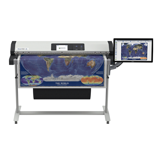
Page 38: Picture 25: Parts Of Monitor Mount
Monitor Mount A monitor mount is available with the floor stand for the WideTEK scanners. The monitor mount is delivered with all necessary tools and mounting material in a plastic bag. A separate list shows the content of the plastic bag. C.4.1 Parts of the Monitor Mount Picture 25: Parts of monitor mount... -
Page 39: Picture 27: Assembling The Base Plate To The Vertical Leg
C.4.2 Assembling the Monitor Mount C.4.2.1 Assembling the Base Plate Tool: Combination wrench, size 13 One of the vertical legs has two threaded bushes. When assembling the floor stand, these two threaded bushes must be positioned outside of the vertical leg. In Picture 15, component #4 shows the position marked with a red circle. -
Page 40: Picture 29: First Step Monitor Mount On Base Plate
C.4.2.2 Monitor Mount fastening on Base Plate Slide the monitor mount at first on the upper side of the base plate. Picture 29: First step monitor mount on base plate Then slide the lower side of the monitor mount over the base plate. Picture 30: Final position of monitor mount at base plate Page 40 Setup Manual... -
Page 41: Picture 31: Fixing The Monitor Mount
Finally fix the monitor mount with two Allen head screws. The Allen head screws are located at the bottom side of the monitor mount. Picture 31: Fixing the monitor mount Use the Allen wrench 2.5 mm to fasten the screws. The monitor mount can easily be moved to a position which matches with the operator’s needs. -
Page 42: Picture 33: Viewer & Job Control Screen
Setup and Adjustments The WideTEK ® / WideTEK ® allows some adjustments to be made directly via the touch screen, e.g. auto focus setting and White Balance calibration. Furthermore, the IP address can be configured and other user settings can be defined. To enter the setup menu, touch the touchscreen at the date and time section ten times successively. -
Page 43: Picture 35: Setup Menu, Start Screen
White Balance Picture 35: Setup menu, start screen The first menu item of the setup menus is the White Balance screen. Whenever it is necessary to perform a White Balance calibration, the touchscreen shows how to position the reference target for optimal calibration. Place the reference target WT36A-WA-01-A as shown. -
Page 44: Picture 36: Ip Address Mask
IP Address Picture 36: IP Address mask To change or define the numeric values which make up an IP address, touch the number in the respective line of IP address, gateway or netmask. An additional window opens where a numeric keyboard allows changing the selected value. -
Page 45: Picture 37: User Settings Menu
User Settings Picture 37: User Settings menu The User Settings menu allows defining the touchscreen menu parameters. Language selector The currently selected language is displayed. The touchscreen menu language can be selected by touching the selection arrow. A list opens, showing the available languages. - Page 46 Display standby after Sets the time of inactivity after the external display and the touchscreen switches to standby. The touchscreen and the external display turn to black. They will return after pressing the standby button or touching the touchscreen. Screen Saver after Sets the time of inactivity after the screen saver is activated.
-
Page 47: Picture 38: Selectable Presets
D.3.1 Change GUI Picture 38: Selectable presets The Change GUI menu shows all predefined settings (presets). By default, the presets Easy and Expert are defined. Selecting App Selection switches the touchscreen to the system start screen, followed by a selection screen with the presets. After selecting one of the presets, the scanner starts in Job Mode with the selected preset. -
Page 48: D.3.3 Show Application Menu
D.3.3 Show Application menu To show the application menu on the touchscreen when starting the scanner, activate this setting. Tap the checkbox in front of Show Application menu. Application menu will not be displayed when the scanner starts. Application menu will be displayed when the scanner starts. D.3.4 Set Application as default To switch directly to the selected application when starting the scanner, activate this... -
Page 49: Picture 40: Time And Date
Time and Date Picture 40: Time and date To change time or date value, touch the value in the respective line. Touch the line at the desired position to move the “cursor”. To delete a digit, place the cursor at the right side of the digit and press the “<=” button. The digits will always be deleted from right to left. -
Page 50: Picture 41: Testsuite Screen
Testsuite Picture 41: Testsuite screen This function will be used for testing purposes. Furthermore the screen shows some status information of the scanner. Lamp on: Switches the integrated lamps permanently on. While the lamps are illuminated, the text on the button changes to Lamp off. Push the button again to switch the lamps off. -
Page 51: Picture 42: User Preset Screen
User Preset Picture 42: User preset screen The User Preset menu is for presets and applications (GUI) selection. Preset Selection Presets contain controls for the scan parameters available in the touchscreen. By default, two presets are defined. Easy Contains only the basic elements of the kiosk application. This preset allows modifying only a few parameters. -
Page 52: Picture 43: Keyboard On The Touchscreen
D.6.1 Preset Selection – Create Preset User defined presets can be created in a few steps. Create Opens a screen with a keyboard. Enter the name for the new preset. Picture 43: Keyboard on the touchscreen ↑ Shifts the keyboard between upper case and lower case characters. ⇐... -
Page 53: Picture 44: Selecting The Preset Content
D.6.2 Preset Selection – Configure Preset Select the preset which should be configured from the list Preset Selection. Touch the button Configure Preset to define the elements which should be displayed in the selected preset. The touchscreen changes from the setup menu to the kiosk application. -
Page 54: D.6.2.2 Saving The Preset Functions
Touch the selection arrow in the first line to change to Enable. This will show the available functions in the second line. Touch the selection arrow in the second line to show the available list of functions. Extensions behind the function names: Automatically switches between button, controller or list when the function is displayed on the touchscreen. -
Page 55: D.6.3 Preset Selection – Delete Preset
D.6.3 Preset Selection – Delete Preset All presets can be deleted except the pre-installed presets Easy and Expert. Select the preset to be deleted from the list. Touch the Delete Preset button. The preset will be deleted. The list of presets will not automatically refresh. To refresh the list, return to the kiosk application (see D.6.5) and open the setup menu again. -
Page 56: Picture 45: Scan2Net Start Screen
Poweruser Level To enter the Poweruser level, start your browser and enter the IP address of the scanner. Picture 45: Scan2Net Start Screen The start screen shows three symbols, which lead to the main categories of the Scan2Net user interface. Launch Scan Application changes to the main screen of the user interface. -
Page 57: Picture 46: Login Level Screen
Setup Menu The login level screen shows the buttons of the login level. All login levels except the level User are password protected. The button Launch Scan Application starts the Scan2Net scan application. The button Back returns to the former screen. Picture 46: Login level screen E.1.1 Selecting the Login Level... -
Page 58: Picture 47: Main Menu Poweruser Level
Main Menu The main menu of the Poweruser level contains all menus of the User level. The Poweruser start screen is structured in six sections. Picture 47: Main menu Poweruser level The buttons below the section titles name the parameters which can be set or modified in the respective section. -
Page 59: E.2.1.1 Navigating Through The Menus
E.2.1.1 Navigating through the menus The bottom line of each screen shows two buttons at the right side: Setup Menu Returns to the login screen. Launch Scan Application Switches to the main screen of the integrated Scan2Net user interface In each selection menu screen below the parameter to be set, the following button is displayed: Back to Main Menu Returns to the Poweruser level start menu (Picture 47). -
Page 60: Picture 48: Device Info
Device Information The section Device Information gives basic information about the scanner. This section is divided in two parts. E.3.1 Device Info Device Info lists the hardware components and provides information about the settings for printer configuration, SMB configuration and many more. To find the information, click the respective links. -
Page 61: Picture 50: Language Selector
Base Settings Base Settings section contains the basic parameters of the scanner. E.4.1 User Settings The section User Settings is divided into subsections. The User Settings start screen is the Power Saving screen. The description of the menu items follows the order of the menus as they are displayed. E.4.1.1 Language Selection Use the function... -
Page 62: Picture 51: File Name
E.4.1.2 File Name Use the function File Name to define a default name which is used when saving images after scanning. Picture 51: File name When defining the default name, variables can be used. To get a list of the variables, click at the link Wildcard characters. -
Page 63: Picture 53: Power Saving
E.4.1.3 Power Saving Note: Power Saving screen is the start screen of the User Settings section. Use the function Power Saving to set the timers for the standby modes. Three settings can be defined. Click on the link Power Saving. Picture 53: Power Saving Click on the selection arrow to open the list of available values for the respective standby mode. -
Page 64: Picture 54: Transport Speeds
E.4.1.4 Transport Speed Two transport speeds are available. They can be selected in the touchscreen as well as in the ScanWizard interface. Use the function Transport Speed to set the values. Picture 54: Transport speeds Click at the selection arrows to display the speeds available for the setting Slow and Normal. -
Page 65: Picture 55: Volume Level
E.4.1.5 Volume Click the link Volume to set the loudspeakers volume of the scanner. Picture 55: Volume level A screen opens and shows a graphic to symbolize the volume. Click at the scale to set the volume level or right-click with the mouse at the arrow and move it to the desired value To return to the previous screen click the button Back to Main Menu . -
Page 66: Picture 56: Start Button Timeout
E.4.1.6 Start Button Timeout Click on the link Start Button Timeout to set delay between pressing the start button and the start of the scan sequence. Picture 56: Start Button timeout Click at the selection arrows to display the available settings for the delay. Click at the desired value to set the time-out period. -
Page 67: Picture 57: Display Parameters
E.4.1.7 Display Use the function Display to define the resolution of the external monitor and to select an ICC profile. Picture 57: Display parameters The external monitor (optional) has a resolution of 1366 x 768 pixels by default. To change the resolution, click the selection arrow in the line Display Resolution. -
Page 68: Picture 58: Guide Plate Middle
E.4.1.8 Guide Plate Middle Use the function Guide Palte Middle to select the color of the guide plate. The settings you make here affect correction algorithms while scanning. Picture 58: Guide plate middle To change the setting, click the selection arrow in the line Color of the installed guide plate. -
Page 69: Picture 59: List Of Available Erasing Methods
E.4.1.9 Secure File Erasing This menu item allows selecting the erasing method for files stored in the scanner memory. Picture 59: List of available erasing methods Click on the selection arrow to open the list of erasing methods. Select the desired method by clicking on the methods name. Setup Manual Page 69... -
Page 70: Picture 60: Kiosk App Selection
E.4.1.10 Kiosk App Use the function Kiosk App to define how the scanner behaves when starting. Picture 60: Kiosk App selection Show Application menu: With factory settings, the scanner’s touchscreen shows at the end of the start sequence the buttons for the applications EasyScan and Scan2Net. By touching the respective button, the scanner starts with the selected application. -
Page 71: Picture 61: Show Warnings Selector
E.4.1.11 Show Warnings Use the function Show Warnings to set warning messages on or off in the user interface. Picture 61: Show Warnings selector E.4.1.12 Validate Certificates Select Yes to activate the validation of certificates when scanning. Picture 62: Validate Certificates selector Setup Manual Page 71... -
Page 72: Picture 63: Ip Configuration Method
E.4.2 Network Configuration The section Network Configuration is divided in nine subsections. The Network Configuration start screen is the IPv4 (Network Interface 0) screen, which is described in chapter E.4.2.2. The following description starts with the IP Configuration Method screen. E.4.2.1 IP Configuration Method The function... -
Page 73: Picture 64: Settings Of Ipv4 (Network Interface 0)
E.4.2.2 IPv4 (Network Interface 0) The function IPv4 (Network Interface 0) allows the operator modifying the parameters for the “Network Interface 0”. This is the primary network and is used for communication with external network devices. Picture 64: Settings of IPv4 (Network Interface 0) The screen shows the parameters for “Network Interface 0”. -
Page 74: Picture 65: Settings Of Ipv4 (Network Interface 1)
E.4.2.3 IPv4 (Network Interface 1) The function IPv4 (Network Interface 1) allows the operator modifying the parameters for the “Network Interface 1”. This is the secondary network and used for communication with internal network devices, e.g. the WLAN module. Picture 65: Settings of IPv4 (Network Interface 1) The screen shows the parameters for the “Network Interface 1”. - Page 75 E.4.2.3.1 Solving a routing conflict in a network As said before, the “Network Interface 0” is used for the communication with external networks; “Network Interface 1” is used for the internal communication with the WLAN module. If the scanner should be operated in an existing network that is configured in the IP address range 10.0.0.x/24 or 10.0.x.x/16 and a host with the IP address 10.0.0.1 is used in this network, a routing conflict will occur.
-
Page 76: Picture 66: Domain Name Server Parameters
E.4.2.4 Domain Name Server This section defines the parameters for the Domain Name Server. Picture 66: Domain Name Server parameters Domain Name Enter the domain name here. Primary DNS Server Enter the address of the primary DNS server here. Secondary DNS Server Enter the address of the secondary DNS server here. -
Page 77: Picture 67: Smb Settings
E.4.2.5 SMB Settings This section defines the parameters for the Settings. Picture 67: SMB Settings Note: The default settings are recommended. SMB Hostname Enter an SMB host name to identify the scanner in the network. Default is the MAC address of the scanner. Use SMB hostname as Select “Yes”... -
Page 78: Picture 68: Firewall Settings
E.4.2.6 Firewall This section allows setting the firewall parameters. Picture 68: Firewall settings The standard ports for the protocols are displayed in brackets. allow all No restriction for the use of the protocol allow only for Enter the IP address or the address range in CIDR notation for the devices which are allowed to use the protocol. -
Page 79: Picture 69: Wireless Lan Basic Settings
E.4.2.7 Wireless LAN (Basic Settings) Use the function Wireless LAN (Basic Settings) to define the basic settings for the WLAN module. Note: This menu is displayed only if a WLAN module is installed and if the settings for IPv4 (Network Interface 1) Wireless LAN (LAN Interface) fit together. -
Page 80: Picture 70: Wireless Lan (Lan Interface)
E.4.2.8 Wireless LAN (LAN Interface) Use the function Wireless LAN (LAN Interface) to define the parameters for the WLAN adapter. Depending at the WLAN module which is integrated into the scanner, the values for IP Address and Default Gateway can vary. Note: This menu is displayed only if a WLAN module is installed and if the settings for IPv4 (Network Interface 1) -
Page 81: Picture 71: Wireless Lan (Security)
E.4.2.9 Wireless LAN (Security) Use the function Wireless LAN (Security) to define the parameters for wireless LAN security. Note: This menu is displayed only if a WLAN module is installed and if the settings for IPv4 (Network Interface 1) Wireless LAN (LAN Interface) fit together. -
Page 82: Picture 72: Wireless Lan (Dhcp)
E.4.2.10 Wireless LAN (DHCP) Use the function Wireless LAN (DHCP) to define the range of IP addresses that can be used by the WLAN module for DHCP access. Note: This menu is displayed only if a WLAN module is installed and if the settings for IPv4 (Network Interface 1) Wireless LAN (LAN Interface) fit together. -
Page 83: E.4.3 Adjust Time & Date
E.4.3 Adjust Time & Date The section Adjust Time & Date is divided into subsections. The Adjust Time & Date start screen is the Manual Adjustment screen. The following description starts with the Time Format screen. To set the time correctly for the scanner, make the adjustments in the following order. Select the time zone. -
Page 84: Picture 73: Time Format
E.4.3.1 Time Format The time shown in the headline of the Scan2Net user interface can be displayed in either 12h or 24h format. Picture 73: Time Format Click on the selection arrow. The differences between 12h and 24h format are shown below. -
Page 85: Picture 74: Time Zone Screen
E.4.3.2 Time Zone Use the function Time Zone to define the time zone for the internal clock of the scanner. Picture 74: Time Zone screen Click on the selection arrow. A list opens. Select the desired time zone from the list. The list will close and the selected setting is effective immediately. -
Page 86: Picture 75: Manual Adjustment
E.4.3.3 Manual Adjustment Use the function Manual Adjustment to set time and date to be displayed in the headline of the Scan2Net user interface. Picture 75: Manual Adjustment To set a value, click on the selection arrow beside the respective value. Select from the list. -
Page 87: Picture 76: Ntp Server Setting
E.4.3.4 NTP Server Use the function NTP Server to define the address of time server. Picture 76: NTP Server setting To connect to a NTP server, the scanner must have a connection to the internet. Ask your network administrator for special information concerning your local network. Enter the address of the NTP server in the line NTP server. -
Page 88: Picture 77: Set Volume
E.4.4 Sound System The section Sound System is divided into three subsections. The Sound System start screen is the Set Volume screen. E.4.4.1 Set Volume Use the function Set Volume to set the loudspeakers volume of the scanner. Picture 77: Set Volume A screen opens and shows a graphic to symbolize the volume level. -
Page 89: Picture 78: Sound Files List
E.4.4.2 Sound Files Use the function Sound Files to list the sounds which are linked to system events. Picture 78: Sound Files list Scroll to the bottom of the list to search and upload new sounds to the scanner. Picture 79: Upload new sound files Click on the button Search to search the directories of your local PC and/or your network for sound files. -
Page 90: Picture 80: Link Events List
E.4.4.3 Link Events Use the function Link Events to change the sounds linked to system events. Picture 80: Link Events list The sound file that is listed at each event is dependent on the language set for the scanner (see chapter E.4.1.1). To identify the language of the sound file, an identifier can be added to the file name. -
Page 91: Picture 81: Options List
To activate an option, a unique key must be entered. The key is valid only with one specific scanner and cannot be transferred to another scanner. The software keys can be purchased at the Image Access Customer Service Portal. Visit the URL portal.imageaccess.de... -
Page 92: Picture 82: Server Certificate Information
E.4.6 Certificates This section shows the server certificates information. Picture 82: Server Certificate information Page 92 Setup Manual... -
Page 93: Picture 83: Selector For Name, Privacy And Owner
E.4.7 Templates The section Templates contains all settings for the data output. By clicking at the links from Remote Printer LDAP Directory Service the current settings for the respective output can be displayed. The selected Owner Filter defines the number of templates for each link. At delivery of the scanner three entries in the Owner Filter are available. -
Page 94: Picture 84: Excluded Wildcard Characters
E.4.7.1 Exclusion of Wildcard Characters for Jobmode Scanning Please note: Valid for firmware before V 6.08. The number of variables which can be used to create file names while scanning in jobmode is limited. When scanning in jobmode, the information for some variables is taken from the last scanned image and is used for naming the selected images respectively the ZIP archive file. -
Page 95: Picture 85: Template List For Remote Printer
E.4.7.2 Remote Printer Picture 85: Template list for remote printer The data output Remote Printer sends the images after scanning to a previously defined network printer. Setup Manual Page 95... -
Page 96: Picture 86: Remote Printer Parameters
E.4.7.2.1 Setup Picture 86: Remote printer parameters Parameter Description Connection Type Choose between IP Networking and SMB Printer Queue. Address Enter the IP address of the printer. (with IP Networking only) Port (9100) Enter the IP port of the remote printer. Default is port 9100. (with IP Networking only) Connection Timeout Choose the timeout for connecting to the remote printer... - Page 97 Remote Printer, continued Parameter Description Network Type Select Homegroup Network or Workgroup Network. (with SMB Printer Queue only) Password Enter the password for the Homegroup Network. (with SMB Printer Queue Homegroup Network only) Server Authentication Select Yes or No. (with SMB Printer Queue ...
- Page 98 Remote Printer, continued Parameter Description Duplex Print Switch on/off printing on both sides of a sheet (duplex). (not with HP Design Jet) Duplex Mode Select between Book and Notepad. Book = binding at the wide side of the paper sheet Notepad = binding at the narrow side of the paper sheet Paper Feed Select the paper feed method for the remote printer.
- Page 99 Accounting Only available with Konica Minolta Bizhub Series Parameter Description Accounting Yes / No Account Name Enter the account name here. Use Password Yes / No Account Password Enter the password for the accounting here. Hold Job Yes / No Job Type Public / Private Hold Key...
-
Page 100: Picture 87: Template List For Ftp Server
E.4.7.3 FTP Server Picture 87: Template list for FTP Server The data output FTP Server sends the images after scanning to a previously defined FTP server. E.4.7.3.1 Setup Picture 88: FTP Server parameters Page 100 Setup Manual... - Page 101 Parameter Description Use a FTP Proxy? Switch on/off the use of an FTP proxy for connecting to a remote FTP server outside the local network. FTP Proxy Address Specify the IP address of the FTP proxy. Port Specify the IP port of the FTP proxy. (if FTP Proxy = Yes) Address Enter the IP address of the remote FTP server.
-
Page 102: Picture 89: Template List For Mail Server
E.4.7.4 Mail Server Picture 89: Template list for Mail Server The data output Mail Server sends the images after scanning via e-mail. Page 102 Setup Manual... -
Page 103: Picture 90: Mail Server Parameters
E.4.7.4.1 Setup Picture 90: Mail Server parameters Parameter Description Address Enter the IP address of the outgoing mail (SMTP/LMTP) server. Port (25) Enter the IP Port of the outgoing mail server. Default: Port 25. TLS/SSL Select Yes if the SSL protocol should be used for the mail transfer. - Page 104 Parameter Description Transaction mode automatic / interactive Use LDAP Directory LDAP directory service can be used to send the mails. To Service? configure the parameters click on the link Options. The following parameters will be displayed if the “Transaction mode” is set to automatic. File Name Enter the file name.
-
Page 105: Picture 91: Template List For Smb Configuration
E.4.7.5 SMB Configuration Picture 91: Template list for SMB Configuration The data output SMB sends the images directly to a network directory. E.4.7.5.1 Setup Picture 92: SMB Configuration parameters Setup Manual Page 105... - Page 106 Parameter Description Port (139) Enter the IP port for the SMB network communication. Default is port 139. Network Type Select between Workgroup Network and Homegroup Network. For detailed information about the correct network type ask your network administrator. Server Authentication Select the authentication method.
-
Page 107: Picture 93: Template List For Web Service Configuration
E.4.7.6 Web Service Configuration This option allows the user to store its files and images in the so called “Cloud”. The “Cloud” is an IT infrastructure where service provider offer via a network computing power or storage space at their servers. The data is no longer stored locally on the computer but on a remote system. -
Page 108: Picture 94: Web Service Parameters
E.4.7.6.1 Setup Picture 94: Web Service parameters Parameter Description Use a Proxy? Switch on/off the use of a proxy for connecting to a remote server outside the local network. Proxy Address Specify the IP address of the proxy. HTTP Proxy Port Enter the port for HTTP communication. - Page 109 Parameter Description Web Service Select from the list the web service where the data should be stored. Available are: • WebDAV • Google Docs • Google Picasa • Post Method Depending on the selected web service the next parameters will vary. Server URL Click on the selection arrow and select the protocol.
- Page 110 Parameter Description Collection Enter the name of the directory where the files should be stored. (only with WebDAV) Upload Mode Select the data format. Currently the file size for the data format “Document” and “File” is limited to 1 MB. (only with Google Docs) If “Document”...
-
Page 111: Picture 95: Template List For Usb Device
E.4.7.7 USB Device Configuration Universal Serial Bus (USB) is a serial bus standard for interface devices, e.g. storage devices. The output option USB enables direct scanning to a USB Standard-A flash memory data storage device. Picture 95: Template list for USB Device E.4.7.7.1 Setup Picture 96: USB Device parameters... - Page 112 Parameter Description Partition Shows the status and available memory of the actual mounted partition on the connected USB flash device. Directory Allows the user to choose a subdirectory on the connected USB drive for storing the scans. File name Shows the current setting of wildcard characters for the automated naming scheme of each produced image file.
-
Page 113: Picture 97: Template List For Metadata
E.4.7.8 Metadata The metadata contain information about the scanned document. The metadata will be included into the file attributes of the file header. Picture 97: Template list for Metadata Setup Manual Page 113... -
Page 114: Picture 98: Metadata Parameters
E.4.7.8.1 Setup Picture 98: Metadata parameters Parameter Description Author The name or organization creating the document or the copyright owner of the document. Title A short title for the scanned document. Subject Abstract of the document. Copyright Marker Select if the scanned document is copyright protected. Copyright Information The copyright message can be entered here. -
Page 115: Picture 99: Template List For Pdf Document
E.4.7.9 PDF Document The PDF document format is a universal format which allows protecting the document against manipulation. PDF documents can be displayed with all common PDF viewers. Picture 99: Template list for PDF document Setup Manual Page 115... -
Page 116: Picture 100: Pdf Document Parameters
E.4.7.9.1 Setup Picture 100: PDF Document parameters Parameter Description PDF Standard Click at the selection arrow and select the desired PDF standard from the list Security System Click at the selection arrow and the desired security system from the list. Page 116 Setup Manual... -
Page 117: Picture 101: Ldap Directory Service Templates
E.4.7.10 LDAP Directory Service Picture 101: LDAP Directory Service templates Setup Manual Page 117... -
Page 118: Picture 102: Ldap Directory Parameters
E.4.7.10.1 Setup Picture 102: LDAP Directory parameters Parameter Description LDAP Server Enter here the address of the LDAP server. Port (389) Enter the port to be used for the connection here. Standard is port 389 Protocol Version LDAP Version 2 / LDAP Version 3 Server Authentication Yes / No Bind... -
Page 119: Picture 103: Update Scanner Firmware
E.5.1 Update Scanner Firmware Upload a new firmware version to the scanner. Picture 103: Update Scanner Firmware The Image Access Customer Service Portal (CSP) at http://portal.imageaccess.de/ offers firmware updates for every Scan2Net scanner. In order to download the appropriate firmware version update for your scanner, you must be a registered user. Log in to the CSP with your personal login name and password. - Page 120 In the screen Update Scanner Firmware (see Picture 103) click on the selection arrow beside “Post update behavior” of the scanner from the list. Select Reboot from the list. This will start the scanner automatically after the firmware update sequence is completed. Browse your local PC and select the previously downloaded firmware update file.
-
Page 121: Picture 104: Scanner Profile
E.5.2 ICC Profiles The section ICC Profiles is divided into the subsections Scanner Profile and Printer Profiles. ICC profiles are integrated in the image file data. First of all, download the respective ICC profile for the device to your local PC. E.5.2.1 Scanner Profile The ICC profile loaded at Scanner Profile adapts the color space between scanner and... -
Page 122: Picture 105: Available Color Spaces
ICC profiles for three color spaces can be uploaded to the scanner. Click the Search button to find an ICC profile for the respective color space. Picture 105: Available color spaces To delete the ICC profile, click on the “Delete” symbol. To get information about the ICC profile, click on the information symbol Picture 106: ICC Profile information Page 122... -
Page 123: Picture 107: Printer Profile Status Message
E.5.2.2 Printer Profiles This function is temporarily not available. The screen shows the following message. Picture 107: Printer profile status message If this function is available, the ICC profiles for printers adapt the color space of the scanner to the color space of the printer used with the scanner. Select Printer Profiles to upload an ICC printer profile. -
Page 124: Picture 109: Icc Profile Information
To delete the ICC profile, click on the “Delete” symbol in the line of the ICC profile to be deleted. To get information about the ICC profile, click on the information symbol in the line of the ICC profile. Picture 109: ICC profile information Selecting the ICC profile to be used: In the S2N user interface of the scanner click on the link Options... -
Page 125: Picture 110: Touchscreen Screensaver
E.5.3 Touchscreen / Desktop This section is divided in the subsections Touchscreen, Desktop and Lock Screen. E.5.3.1 Touchscreen This section allows installing a screensaver for the touchscreen. GIF animations are suitable as screensavers for the touchscreen. Picture 110: Touchscreen screensaver The installed screensavers are listed. -
Page 126: Picture 111: Desktop Screensaver List
E.5.3.2 Desktop Screen This section allows the operator to install background images for the external monitor. Picture 111: Desktop screensaver list The installed desktop images are listed on the screen. To delete a desktop image, click on the “Delete” symbol at the right side of the line. -
Page 127: Picture 113: Lock Screen Screensaver List
E.5.3.3 Lock Screen This section allows the operator to select images for lock screen. The lock screen is displayed when the scanner is in stand-by mode. Picture 113: Lock screen screensaver list Click in the column Select to select the Lock Screen image. To delete a desktop image, click on the “Delete”... -
Page 128: Picture 114: Java Apps
E.5.4 Java Apps This section enables installing and selecting Java applications for special user-defined tasks. Picture 114: Java Apps The installed Java Apps are listed on the screen. To delete a Java App from the list, click on the “Delete” symbol at the right side of the line. -
Page 129: Picture 115: Status Message
E.5.5 PDF Cover Sheet This function is temporarily not available. The screen shows the following message. Picture 115: Status message If this function is available, this section is used to configure the automatic addition of a PDF cover sheet to each multipage PDF created through the scan process. Picture 116: PDF Cover Sheet The preinstalled cover sheets are displayed in the list. -
Page 130: Picture 117: Adjustment Main Screen
Adjustments & Support E.6.1 Adjustments The Adjustment screen shows the links to the optical and mechanical adjustments. Picture 117: Adjustment main screen White Balance Adjustments section offers the measurement routines to execute the white balance, for the streak compensation, and to set the brightness correction. Enhanced Adjustments allows fine tuning the transport speed. -
Page 131: Picture 118: White Reference Target On Document Table
E.6.1.1 White Balance The white balance function is the most important function for consistent image quality. During the white balance measurement, all light sources are combined and illuminate the target. The measurement results in a correction function for the scan area. Picture 118: White Reference Target on document table Place the White Reference Target on the document table as shown in the picture above. -
Page 132: Picture 119: Streak Compensation
E.6.1.2 Streak Compensation Streak Compensation allows modifying the sensitivity of the camera for correction of errors in the image in transport direction. Picture 119: Streak Compensation Click with the mouse at the desired position between weak and strong. It is recommended to use the default setting Normal. Modify the setting in small steps, rescan and check the result. -
Page 133: Picture 120: Brightness Correction Factor List
E.6.1.4 Brightness Correction The brightness correction function does not perform any measurements; it only allows setting a correction factor for the brightness. The interval of the correction factor is ± 2 dB. Picture 120: Brightness Correction factor list Click on the selection arrow to set the desired correction factor. The correction factor will be effective immediately. -
Page 134: Picture 121: Transport Speed Fine Tuning
E.6.1.5 Transport Speed This function allows to increase or to decrease the speed in steps of ± 1 ‰ and ± 0.1 ‰. Click with the mouse at the button to modify the speed. The current value is displayed between the buttons. Picture 121: Transport speed fine tuning Page 134 Setup Manual... -
Page 135: Picture 122: Stitching Start Screen
E.6.1.6 Stitching The Stitching Target WT36C-Z-02-A is the recommended test document for the stitching function. Alternatively millimeter paper sheets, size at least ISO A3, can be used. Picture 122: Stitching start screen Place the stitching target as shown at the screen at the document table. Click on Next Step to start the stitching measurement sequence. -
Page 136: Picture 124: Display Of Cut Outs (Wt48)
Picture 124: Display of cut outs (WT48) WideTEK ® 36: The left cutout shows the stitching between the images of camera 1 and camera 2, the right cutout shows the stitching between the images of camera 2 and camera 3. WideTEK ®... -
Page 137: Picture 125: Log Files Overview, Software Version 6.X
E.6.2 Log Files E.6.2.1 Show Log Files While working with the scanner, the activities will be logged in several log files. Picture 125: Log files overview, software version 6.x Log file Content FTP Log FTP transfers will be logged with all transfer data. SMTP Log SMTP transfers will be logged with all transfer data. -
Page 138: Picture 126: Selection Box At The Bottom Of The Screen
Click on the button for the desired log file to view its contents. Picture 126: Selection box at the bottom of the screen Depending at the selected log file, the amount of information varies. Click on the button Download to save the log file. A dialog box opens where the operator can select between saving and opening the log file. -
Page 139: Picture 127: Available Test Target
E.6.3 Scan Test Targets For system analysis and troubleshooting, three test targets can be used. The CSTT test target and the IT8 test target included with the scanner. E.6.3.1 Scan CSTT Test Target Click on the respective button to select the CSTT test target for the scan sequence. Picture 127: Available test target The next screen shows the position of the CSTT test target. -
Page 140: Picture 129: Request After Scanning The Test Target
The test sequence will take approximately 30 seconds. After scanning, the image will not be displayed. A small window – depending on the browser used for scanning – opens. Select between opening the image with an appropriate software application and saving the image. -
Page 141: Picture 130: Utt Test Target On Glass Plate
E.6.3.2 Scan UTT Test Target Click on the respective button to select the UTT test target for the scan sequence. Note: The UTT test target is not included with the scanner. Picture 130: UTT test target on glass plate The procedure is the same as described with the CSTT test target. The resulting image differs in the name because of the other test target. -
Page 142: Picture 132: Hardware Test Suite Start Screen
E.6.4 Hardware Test Suite This menu item here is the network analyzer. Picture 132: Hardware Test Suite start screen E.6.4.1 Network Analyzer This menu allows to test the network performance and to view the packet statistics. Picture 133: Network Analyzer menu items Select either Perform Speed Test or Packet Statistics. -
Page 143: Picture 134: Network Analyzing Parameters
E.6.4.1.1 Perform Speed Test Click on Perform Speed Test to check the date transfer speed. Picture 134: Network Analyzing Parameters Target Address Enter an IP address which can be accessed from the scanner to test the data transfer speed. Packet Count Click on the selection arrow to set the number of transferred packets. -
Page 144: Picture 135: Measured Time
The result of the measurement is displayed at the next screen. Picture 135: Measured Time The bar graphic shows the three values: Minimum The fastest transfer time between the scanner and the target address. Average The average time for all transferred packets. Maximum The maximum transfer time during the test. -
Page 145: Picture 137:Wlan Module Successful Installed
Additional Hardware E.7.1 Wireless LAN Use this function after installing a WLAN module to the scanner or when the installed WLAN module has been replaced. Click at Wireless LAN . The module will be initialized. The screen shows a message. Picture 137:WLAN module successful installed Setup Manual Page 145... -
Page 146: Picture 138: Wake Up Remote Host
Administrative Settings E.8.1 Wake up Remote Host If an external PC is used with the scanner, it is helpful to start the PC at the same time when the scanner starts. This can be done by activating the Wake up Remote Host function. Picture 138: Wake up Remote Host The requirements for using this function: •... -
Page 147: Picture 139: Change Password Menu
E.8.2 Change Password It is recommended to modify the password often, to protect the limited access to the Poweruser level. Click on Change Password . Picture 139: Change password menu Select Level Click on the selection arrow to open the list of log-in levels. Select the log-in level, for which the password should be changed. -
Page 148: Picture 140: Small Window At Bottom Line With Inquiry For Action
E.8.3 Backup Settings To store the current settings of the scanner, a ZIP archive file can be created. Click on Backup Setting to create the ZIP archive. Depending on the browser used, a small window opens at the bottom line of the current window or a separate window opens. -
Page 149: Picture 141: Restore Setting From Zip File
E.8.4 Restore Settings With this function, the ZIP file stored with the “Backup Settings” function can be loaded to the scanner. Click on Restore Settings Picture 141: Restore setting from ZIP file To find the ZIP archive, click on Search and browse the directory structure to find the desired ZIP archive file. -
Page 150: Picture 143: Enter Password To Lock The User Interface
E.8.5 Lock Web App This function locks the Scan2Net user interface. When the Scan2Net user interface is locked, the scanner can only be controlled by the touchscreen or by external software. Picture 143: Enter password to lock the user interface New Password Enter the new password. -
Page 151: E.9 Resets & Default Values
Resets & Default Values E.9.1 Set Scanner Defaults This function enables saving settings for color mode, resolution, document mode as well as network parameters and other parameters. When powering up, the scanner starts with the saved settings. To modify the settings, switch to the Scan2Net user interface and set all parameters to the desired values. -
Page 152: F.1 Scanner Specifications
® Technical Data WideTEK 36 / 48 Scanner Specifications WideTEK ® Optical System Maximum document width 37.4 inch / 950 mm Scan width Max. 36 inch / 915 mm Scanner resolution 1200 x 1200 dpi Optical resolution 1200 x 600 dpi Pixel dimension 9.3 x 9.3 µm Sensor type... -
Page 153: F.2 Document Specification
WideTEK ® Optical System Maximum Document Width 50 inch / 1270 mm Scan Width: Max. 48 inch / 1220 mm (WideTEK 48) Scanner resolution 1200 x 1200 dpi Optical Resolution 1200 x 600 dpi Sensor Type: 4x Tri-Color CCDs, encapsulated and dust-proof... -
Page 154: F.3 Electrical Specifications
Electrical Specifications External Power Supply Voltage 100 – 240 V AC Frequency 47 – 63 Hz Inrush current 120 A max / 264 V AC Efficiency 85 % Operating temperature 5 to 40 °C / 40 to 105 °F Operating humidity 20 …... -
Page 155: F.4 Dimensions And Weight
Dimensions and Weight WideTEK ® F.4.1 Scanner outer dimensions 228 x 1095 x 507 mm (H x W x D) 9 x 43.1 x 20 inch Scanner outer dimensions 1070 x 1095 x 507 mm (H x W x D) (incl.
Need help?
Do you have a question about the WideTEK 48 and is the answer not in the manual?
Questions and answers