Table of Contents
Advertisement
Quick Links
Advertisement
Table of Contents

Subscribe to Our Youtube Channel
Related Manuals for Image Access WideTEK 36ART


Summary of Contents for Image Access WideTEK 36ART
- Page 1 WideTEK® 36ART Setup Instructions English 09/2017...
-
Page 2: Table Of Contents
Contents Information about the Instructions and the Manufacturer ....... 4 Keep Instructions with the Scanner ............4 Design Features in Text ................5 Design Features in Pictures..............5 Associated Documents ................6 Copyright ....................6 Contact Data of the Manufacturer in Germany ........7 Technical Support .................. - Page 3 Perform Setup ..................21 Change the Menu Language ..............21 Inserting and Aligning the Scan Table ........... 23 Placing an Object to be Scanned on the Scan Table ......24 Scanning and Watching the Object Move Through the Scanner... 27 Preparing Whitebalance ................
-
Page 4: Information About The Instructions And The Manufacturer
Information about the Instructions and the Manufacturer Information about the Instructions and the Manufacturer These instructions show you how to safely prepare and perform the setup for the art scanner WideTEK® 36ART-600. The WideTEK® 36ART-600 scanners are hereinafter referred to as "Scanner". In these instructions, the start button is called "power button". -
Page 5: Design Features In Text
Information about the Instructions and the Manufacturer Design Features in Text Many text passages in these instructions have been formatted to indicate specific elements, as illustrated below: Normal text BUTTONS OF THE SCREEN PAGE "Menu names" ➢ Action steps • Enumeration of the first level Cross-references Tips contain additional information, such as special information to prepare for and perform the setup. -
Page 6: Associated Documents
Image Access GmbH. © Image Access GmbH 2017 All rights reserved. Trademarks Scan2Net®, Scan2PAD®, Bookeye® and WideTEK® are registered trademarks of Image Access, all other trademarks are the property of their respective owners. -
Page 7: Contact Data Of The Manufacturer In Germany
42281 Wuppertal Phone: +49-202-27058-0 E-Mail: documentation@imageaccess.de Internet address: www.imageaccess.de Technical Support Image Access technical support can be reached at the e-mail address: support@imageaccess.de. Contact Data of the Manufacturer in the U.S. Image Access LP 2511 Technology Drive, Suite 109 Elgin... -
Page 8: Safety
Safety Safety Intended Use The scanner is used for scanning fine art and other material and documents. The fine art must comply with the characteristics described in the technical specifications. The scanner is designed for use in enclosed spaces in the commercial sector. Intended use also includes observing and following all information provided in these instructions, especially the safety instructions. - Page 9 ➢ Do not use the scanner if it is visibly damaged. In this case, unplug the power cord from the wall outlet. Contact Image Access technical support, see section Technical Support starting at page 7. Avoid Burns ➢...
-
Page 10: Avoiding Property Damage And Malfunctions
Safety Avoiding Property Damage and Malfunctions ➢ Ensure adequate ventilation to comply with the environmental conditions. ➢ Do not place the scanner in the vicinity of devices that emit strong electromagnetic radiation. ➢ Do not lean on the scanner. ➢ Ensure that the thickness of the original to be scanned does not exceed the current clearance between 100 and 200 mm. -
Page 11: Design Features Of Warning Notices
Safety Design Features of Warning Notices In these instructions, the following warning information can be found: WARNING Notices with the word WARNING warn about a dangerous situation that could lead to death or serious injuries. CAUTION Notices with the word CAUTION warn about a situation that could lead to light or medium-scale injuries. -
Page 12: Description
Description Description Purpose and Function The scanner is used for scanning fine art and other objects as well as documents of all kind. It is designed for use in enclosed spaces in the commercial sector. The originals must conform to the characteristics according to the technical data. -
Page 13: Rear View
Description Rear View The following diagram shows the rear view of the WideTEK® 36ART model. Name 24 Vdc connector for external power supply Main switch Recovery key connector Network connector... -
Page 14: Setup Menu Overview Screen
Description Setup Menu Overview Screen Name Buttons and parameters Menu name Button to leave the setup menu to the start screen Display the online help Serial number IP address Firmware version... -
Page 15: Rating Plate
Description Rating Plate The rating plate is attached to the back of the scanner. The following figure shows the WideTEK® 36ART rating plate. -
Page 16: Prepare For Setup
Prepare for Setup Prepare for Setup Connect the Power Supply WARNING Risk of electric shock due to incorrect connection. ➢ Ensure that the power receptacle intended for the connection is properly grounded. ➢ Ensure that the power receptacle intended for the connection of the scanner is properly fused. -
Page 17: Establish The Network Connection
Prepare for Setup Establish the Network Connection CAUTION Incorrect laying of the connection cables can cause tripping. Fractures, contusions and bruises can be the result. ➢ Place the connecting cables so that nobody can trip over them. To establish the network connection, proceed as follows: ➢... -
Page 18: Switch On The Scanner
Prepare for Setup Switch On the Scanner To switch on the scanner, proceed as follows: ➢ Press the MAIN SWITCH (1) on the back to the "I" position. The following diagram shows the scanner model WideTEK® 36ART. To start the scanner from standby mode, proceed as follows: ➢... - Page 19 Prepare for Setup After a short wait, the "ScanWizard Start screen" is displayed in English.
-
Page 20: Switch Off The Scanner
Prepare for Setup Switch Off the Scanner To switch the scanner to standby mode after performing the setup, proceed as follows: ➢ Touch the blue illuminated power button (2) and confirm the action in the dialog on the touchscreen. The scanner shuts down. This process can take up to 40 seconds. The power button lights up green. -
Page 21: Perform Setup
Perform Setup Perform Setup Change the Menu Language To change the menu language, proceed as follows: ➢ Tap the LANGUAGE (1) button. - Page 22 Perform Setup A window for selecting the language appears. ➢ Tap the desired language. The window for selecting the language is closed. The "Start screen" is displayed.
-
Page 23: Inserting And Aligning The Scan Table
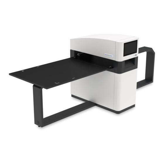
Perform Setup Inserting and Aligning the Scan Table The scan table of the WideTEK 36ART, which holds the objects to be scanned, can be inserted and moved on the scanner by hand. The scan table rests on the runways and the start position is on the left side. -
Page 24: Placing An Object To Be Scanned On The Scan Table
Perform Setup Placing an Object to be Scanned on the Scan Table ➢ Place the object to be scanned on the table so that it is below the red laser lines. Depending on the size of the material to be scanned, either both laser lines should be fully on the object or if the object is smaller, one laser line should be fully on the object and the other laser line must be fully off the object. - Page 25 Perform Setup ➢ The WideTEK 36ART Control Panel window appears. Camera Position Control Button Name UP END STOP DOWN DOWN END BASE POSITION...
- Page 26 Perform Setup 1.Drive the camera to the base position. 2.Drive the camera up using the ▲ button until the right laser focus position is found. 3.Drive the camera up until the right camera position is found. 1. Camera height in 2.
-
Page 27: Scanning And Watching The Object Move Through The Scanner
Perform Setup Scanning and Watching the Object Move Through the Scanner When the scan has been started, the operator can observe how the object moves under the illumination line and the image is scanned line by line as the object moves through the scanner. When the object has passed through the illumination line, the scan is complete and can be stopped by pressing the stop button. - Page 28 Perform Setup ➢ The WideTEK 36ART Control Panel window appears.
- Page 29 Perform Setup ➢ Drive the camera in its start position, using the BASE POSITION button (1). ➢ Drive the scan table in its start position, using the ◄ and ► buttons, so that the top edge of the scan table runs alongside the right side of the scanner.
- Page 30 Perform Setup ➢ After the White Reference Target WT36C-Z-01-A has been placed in front of the pressure rollers, manually move the scanning table carefully to the point where the middle of the black line is flush to the left side of the scanner.
-
Page 31: Activate The Setup Menu
Perform Setup Activate the Setup Menu To activate the setup menu, you have to log in on the scanner. Proceed as follows: ➢ Tap the USER DEFAULT button (1). The User Login window appears. - Page 32 Perform Setup ➢ In the User Login window, select the user Poweruser. ➢ To enter the credentials, tap with your finger on the "Password" input field. ➢ Activate the "Show" box to see the password while entering it.
- Page 33 Perform Setup The screen keyboard is displayed. ➢ Enter the word "Poweruser" in the field "Password" (2). ➢ Please note that the input is case sensitive. ➢ To complete the password entry, press OK (1).
- Page 34 Perform Setup The User Login window appears. ➢ To complete the log in, press USER LOGIN.
- Page 35 Perform Setup The ScanWizard window appears. ➢ To start the Setup Menu, press the button SETUP MENU (1).
- Page 36 Perform Setup The "Setup Menu" screen is displayed. White Balance: Display the "White Balance" submenu Testsuite: Display the "Test Suite" submenu IP Address: Display the "IP Address" submenu User Settings: Display the "User Settings" submenu Time and Date: Display the "Time and Date" submenu ➢...
-
Page 37: Perform White Balance
Perform Setup Perform White Balance ➢ On the "Setup Menu" screen, tap on WHITE BALANCE (1). - Page 38 Perform Setup The "White Balance" screen is displayed. Calibrate: Start white balance Delete White Delete existing white balance data Balance Data: The white balance is used to ensure the quality of the scan results. The white balance will be carried out using a test target. The test target is marked as follows: •...
- Page 39 Perform Setup ATTENTION! Impairment of the scan quality can occur if an improper test target for the white balance is used. ➢ Make sure that the test target is free from wrinkles, discolorations, cracks or other damage. ➢ Store the test target for the white balance in a safe place protected from daylight.
- Page 40 Perform Setup ➢ Tap on CALIBRATE (1).
- Page 41 Perform Setup ➢ Tap on NEXT STEP (1).
- Page 42 Perform Setup The white balance starts and the calibration is performed. During the white balance, a rotating icon appears. The test target is transported forward and returned. The entire white balance sequence takes about 50 seconds. Then, the white balance result is displayed as shown in the example below.
- Page 43 Perform Setup On an error-free white balance calibration, the result is displayed in green. An incorrect result is displayed in red. If this is the case, the white balance starts over again. ➢ To perform the white balance again, tap NEW VALUES (2). ➢...
- Page 44 Perform Setup ➢ To delete the stored data of the white balance calibration, tap DELETE WHITE BALANCE DATA (2). ➢ After deleting the stored data, run the white balance again, as described. ➢ If problems arise during the white balance calibration, contact Image Access technical support, see section Technical Support starting at page ➢...
-
Page 45: Assign The Ip Address
Perform Setup Assign the IP Address Manually Assign the IP Address To manually assign the IP address, proceed as follows: ➢ On the "Setup Menu" screen, tap on IP Address (1). - Page 46 Perform Setup The "IP Address" screen is displayed. Set network Accept the network settings provided settings: Reset to Factory: Reset to factory settings IP Address: Input field for the IP address Subnet Mask: Input field for data on the subnet mask Gateway: Input field for the gateway address IP Configuration...
- Page 47 Perform Setup ➢ Tap the "IP Address" (1) field.
- Page 48 Perform Setup The "IP Address" window is displayed. ➢ Enter the IP address (1).
- Page 49 Perform Setup ➢ To delete a digit, move the cursor to the right, behind the digit to be deleted and tap DEL (1).
- Page 50 Perform Setup The arrow keys left (1) and right (2) next to the number "0" move the cursor within the chosen row. ➢ To complete the entry, press OK (3). ➢ Perform the settings for gateway and subnet mask in the same way.
- Page 51 Perform Setup ➢ To save the network settings, tap SET NETWORK SETTINGS (2). ➢ To return to the previous submenu, tap BACK (1).
- Page 52 Perform Setup Automatically Assign the IP Address To automatically assign the IP address, proceed as follows: ➢ On the "Setup Menu" screen, tap on IP Address (1).
- Page 53 Perform Setup ➢ In the selection menu "IP Configuration Method", select the "DHCP" (2) entry. ➢ To return to the previous submenu, tap BACK (1).
-
Page 54: Modify User Settings
Perform Setup Modify User Settings ➢ On the "Setup Menu" screen, tap on USER SETTINGS (1). - Page 55 Perform Setup The "User Settings" screen is displayed. Default: The scanner default settings will be established again Language: Select language Display standby Define the period of inactivity, until an optional after: external monitor and the touchscreen switch to the standby mode Screen Saver after: The period of inactivity is defined until the screen saver is activated...
- Page 56 Perform Setup Select Language To select the language, proceed as follows: ➢ Tap the on the selection arrow of the selection menu "Language" to display the list of languages. ➢ Tap the desired language (2). ➢ To return to the previous submenu, tap BACK (1).
- Page 57 Perform Setup Set Standby Times To set the standby times, proceed as follows: ➢ Tap the selection arrow of the selection menu. ➢ Tap on the desired entry (2). ➢ Perform the settings for the screen saver and the device standby in the same way.
-
Page 58: Set The Time And Date
Perform Setup Set the Time and Date ➢ On the "Setup Menu" screen, tap on TIME and DATE (1). - Page 59 Perform Setup The screen "Time and Date" appears. Enter new time: Enter hours and minutes with the arrow keys Enter new date: Open a calendar to set the date Store time and Accept the set values date: Time Zone: Select a time zone...
- Page 60 Perform Setup To set the time, proceed as follows: ➢ Tap the "Enter new time" field. ➢ To set the time later, tap the up arrow (2). ➢ To set the time earlier, tap the down arrow (2). ➢ To save the modified time, click STORE TIME AND DATE (3). ➢...
- Page 61 Perform Setup To set the date, proceed as follows: ➢ Tap the "Enter new date" field. A calendar (3) is displayed. ➢ Select the appropriate date in the calendar (3). ➢ To set the month and year, tap the arrow keys (2, 4) at the top of the calendar.
- Page 62 Perform Setup ➢ To select the time zone, tap the selection arrow (3). A selection list with available time zones is displayed. ➢ Select the appropriate time zone. ➢ To save the time zone, click STORE TIME AND DATE (2). ➢...
-
Page 63: Perform Test Suite
Perform Setup Perform Test Suite ➢ On the "Setup Menu" screen, tap on TESTSUITE (1). - Page 64 Perform Setup The "Testsuite" screen is displayed. Information about Display the current values for: the mainboard: Temperature of PCB and CPU cores, fan speed, PCB voltages Information about Inputs will always appear green the inputs: Information on end When the end position switches are activated, the position switches: display changes from green to red, for as long as the switches are activated...
- Page 65 Perform Setup Test the LED Lamps Functionality ➢ To check whether both LED lamps working properly, select from the "Lamp" menu the entry "Lamp 1" and "Lamp 2" one after the other (2). The LED lamps are illuminated. ➢ To return to the previous submenu, tap BACK (1). Test the Laser Functionality ➢...
-
Page 66: Technical Specifications
Technical Specifications Technical Specifications Scanner Specification Optical System Maximum document size 914 x 1524 mm / 36 x 60 in Scan width 915 mm / 36 in Scanner resolution 600 × 600 dpi Optical resolution 600 × 600 dpi Pixel size 9,3 ×... -
Page 67: Ambient Conditions
Technical Specifications Ambient Conditions Ambient temperature during +5 to +40 °C operation Storage temperature 0 to +60 °C Relative humidity 20 to 80% (non-condensing) Noise development ≤ 35 dB(A) (Scanning) ≤ 25 dB(A) (Standby) -
Page 68: Electrical Data
Technical Specifications Electrical Data External Power Supply Input voltage 100–240 Vac Frequency 47–63 Hz Output voltage 24 Vdc Output current 6,25 A ECO Standard CEC Level VI Scanner Input voltage 24 Vdc Input current (non fused) max. 5 A Power consumption Sleep mode ≤... -
Page 69: Document Specifications
Technical Specifications Document specifications Maximum scan heights 100 mm / 4 in Document thickness 200 mm / 8 in Maximum permissible document 10 kg weight 22 lb. (E.g. Canvas up to max. 100 mm in a frame up to 200 mm thickness). Dimensions and Weight Scanner outer dimensions with 1380 x 3275 x 1280 mm...
Need help?
Do you have a question about the WideTEK 36ART and is the answer not in the manual?
Questions and answers