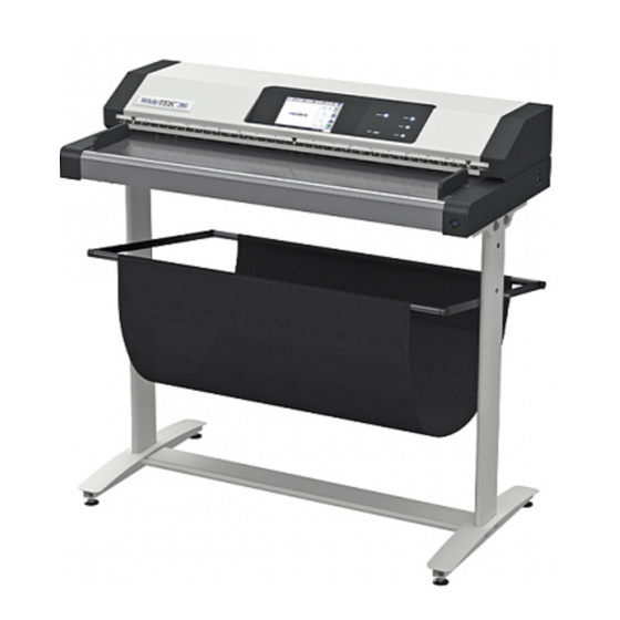
Image Access WideTEK 36 Setup Instructions
Hide thumbs
Also See for WideTEK 36:
- Operation manual (129 pages) ,
- Instruction manual (124 pages) ,
- Setup instructions (76 pages)
Table of Contents
Advertisement
Quick Links
Advertisement
Table of Contents

Related Manuals for Image Access WideTEK 36


Summary of Contents for Image Access WideTEK 36
- Page 1 WideTEK® 36/44/48 Setup instructions English 02/2021...
-
Page 2: Table Of Contents
Table of Contents Revision overview ..................4 Notes on the instructions and the manufacturer ........4 Keep instructions available ..............4 Design features in the text ..............5 Design features in illustrations ..............6 Associated documents ................6 Copyright ....................7 Contact details of the manufacturer in Germany ........ - Page 3 Prepare setup ..................21 Connecting the power supply ..............21 Establish network connection ............... 22 Place the scanner on the optional base ..........22 Connecting the foot switch ..............23 Connecting the optional monitor ............23 Connect optional touch screen ............. 24 Switch on scanner .................
-
Page 4: Revision Overview
Revision overview Revision overview Date Rev. Name Description of Reason for change change 09.12.2020 First draft First published version 25.02.2021 Second draft Updated version Notes on the instructions and the manufacturer This manual will help you to safely prepare and perform the setup for the WideTEK®... -
Page 5: Design Features In The Text
Notes on the instructions and the manufacturer Design features in the text Various elements of this guide have specified design features. This allows you to easily distinguish the following elements: normal text BUTTONS OF THE SCREEN "menu labels" ➢ Action steps •... -
Page 6: Design Features In Illustrations
Notes on the instructions and the manufacturer Design features in illustrations When elements are referred to in a legend or in the running text, they are given a number (1). Associated documents The accompanying documents include: • Unpacking and packing instructions •... -
Page 7: Copyright
Tel.: +49-202-27058-0 E-Mail: dokumentation@imageaccess.de Internet address: www.imageaccess.de Technical support You can reach Image Access GmbH technical support at the following e- mail address: support@imageaccess.de. Contact details of the manufacturer in the USA Image Access LP 2511 Technology Drive, Suite 109 Elgin... -
Page 8: Device Safety
Device safety Device safety Intended use The scanner is used to scan images and documents of all types. The documents must comply with the characteristics according to the technical specifications. The scanner is intended for use in closed rooms in the commercial sector. -
Page 9: Basic Safety Instructions
AC adapter with an AC adapter of the same type. ➢ Do not use the scanner if it is visibly damaged. In this case, unplug the power cord from the power outlet. Contact Image Access technical support, see section Technical Support from page 7. -
Page 10: Avoid Material Damage Or Malfunctions
Device safety Avoid material damage or malfunctions ➢ To comply with the environmental conditions, ensure good room ventilation. ➢ Do not place the scanner near equipment that emits strong electromagnetic radiation. ➢ Always place the scanner on a suitable, stable table or on the optionally available base. -
Page 11: Design Features Of Warnings
Device safety Design features of warnings This manual contains the following warnings: WARNING Notes with the word WARNING warn of a dangerous situation that can possibly lead to death or serious injury. CAUTION Notes with the word CAUTION warn of a situation that may result in minor or moderate injury. -
Page 12: Description
Description Description Task and function The scanner is used to scan images and documents of all types. The characteristics of the documents, such as size, thickness, etc., must comply with the specifications found in the technical data. The scanner is intended for use in closed rooms in the commercial sector. -
Page 13: Overview Widetek® 36/44/48
Description Overview WideTEK® 36/44/48 Designation Document attachment Touchscreen USB port Control panel buttons Main switch Paper guide Power button Scanner WT 44 can be extended to a WT48 by a software option. - Page 14 Description Control panel buttons The control panel of the WideTEK® 36/44/48-600 has three keys with additional functions. Name Function Start Starts a scan job Scan Starts a single scan. Send Saves a scan job...
-
Page 15: Overview Back Side
Description Overview back side The following figure shows the back of the scanner. Designation Connection socket for foot switch Connection socket 24 V DC for external power supply unit USB port Network connection socket DisplayPort connector socket Recovery button... -
Page 16: Overview Screen Page For The Setup Menu
Description Overview screen page for the setup menu Designation Buttons and parameters Display of the menu designation Display of online help Button for exiting the setup menu to the start screen Display of the serial number Display of the IP address Display of the firmware version Online Help display is only available when a second touch screen is connected to the scanner. -
Page 17: Rating Plate
Description Rating plate The rating plate is located on the back of the scanner. The following figure shows the rating plate of the WideTEK®36 model. - Page 18 Description The following figure shows the rating plate of the WideTEK®44 model.
-
Page 19: Serial Number
Description The following figure shows the rating plate of the WideTEK®48 model. Serial number The serial number of the scanner is located on the back of the device. Keep the serial number handy when calling for support. User interfaces The scanner can be operated in five ways. •... -
Page 20: Installation Site
Installation site Installation site Environmental conditions When operating the scanner, make sure that the room is well ventilated to ensure the operating conditions. The installation site must be chosen so that • the side distance between scanner and wall is at least 100 mm, •... -
Page 21: Prepare Setup
Prepare setup Prepare setup Connecting the power supply WARNING Risk of electric shock due to incorrect connection. ➢ Ensure that the mains socket is earthed in accordance with local regulations. CAUTION Incorrect routing of the connection cables can cause tripping, broken bones, bruises and crushing. ➢... -
Page 22: Establish Network Connection
Prepare setup Establish network connection CAUTION Incorrect routing of the connection cables can cause tripping, broken bones, bruises and crushing. ➢ Lay the connection cables so that no one can trip over them. To establish the network connection, follow the steps below: ➢... -
Page 23: Connecting The Foot Switch
Prepare setup Connecting the foot switch CAUTION Incorrect routing of the connection cables can cause tripping, broken bones, bruises and crushing. ➢ Lay the connection cables so that no one can trip over them. ➢ Connect the foot switch plug to the foot switch connector on the back of the scanner. -
Page 24: Connect Optional Touch Screen
Prepare setup Connect optional touch screen CAUTION Incorrect routing of the connection cables can cause tripping, broken bones, bruises and crushing. ➢ Lay the connection cables so that no one can trip over them. To connect an optional touch screen, follow these steps: ➢... -
Page 25: Switch On Scanner
Prepare setup Switch on scanner To switch on the scanner, proceed as follows: ➢ Press the MAIN switch (1) to the "I" position. The following figure shows the WideTEK®36 model. The scanner is in stand-by mode. - Page 26 Prepare setup To exit stand-by mode, proceed as follows: ➢ Press the power button (2). The power button lights up blue. The scanner performs a system test. After a short waiting time, the "Startup Screen" screen is displayed in English.
-
Page 27: Switch Off Scanner
Prepare setup Switch off scanner To switch the scanner to stand-by mode after performing the setup, proceed as follows: ➢ On the Select Application screen, tap POWER OFF (1). You can also press the POWER button briefly to access this menu. Do not press the POWER button for longer than 5 seconds, otherwise the scanner will switch off hard. - Page 28 Prepare setup If you will not be using the scanner for an extended period of time, you can further reduce power consumption by turning off the stand-by power. To do this, follow the steps below: ➢ Make sure the scanner is in stand-by mode. ➢...
-
Page 29: Perform Setup
Perform setup Perform setup Setup Wizard The Setup Wizard is displayed on the touchscreen immediately after the startup process is complete. The Setup Wizard allows the user to perform the most important settings on the touch screen during the initial installation of a Scan2Net scanner. After the Setup Wizard has been successfully completed, the scanner can be used immediately without any further settings. - Page 30 Perform setup All user interfaces of the Setup Wizard are described in the online help. To exit the Setup Wizard you have to deactivate it in the LAUNCH SCAN APPLICATION tile. Starting the Setup Wizard after booting the scanner can be reactivated in the DEVICE SETUP section of Scan2net.
-
Page 31: Perform Calibrations
Perform calibrations Perform calibrations Activate setup menu To activate the setup menu, you must log in. To do this, proceed as follows: ➢ Tap on the OPERATION SYMBOL (1). - Page 32 Perform calibrations The login screen is displayed. ➢ Enter the login data in the login window. ➢ To do so, tap the corresponding input field with your finger. ➢ The on-screen keyboard is displayed. ➢ Enter "Poweruser" in both input fields. ➢...
- Page 33 Perform calibrations Overview screen page for the setup menu White balance: Display the white balance submenu. Display the "Camera settings" and "Stitching" Camera Settings: submenus. Test Suite: Display the "Test Suite" submenu IP Address: Display the "IP Address" submenu Wireless Network: Display the "Wireless Network"...
-
Page 34: System Restore
System Restore System Restore Solid State Disk Software Error The file system and Linux operating system of a Scan2Net scanner are very robust and fault tolerant. The file system is capable of repairing itself even if the system loses power during a hard drive write, which would almost certainly damage any Windows, Android, or MAC operating system based computer. -
Page 35: System Restore To Factory Defaults
System Restore System Restore to Factory Defaults The recovery procedure is a simple process: Step Action Turn off the scanner either from the touchscreen, from the Scan2Net application currently in use, or by pressing the POWER button. If the device does not go into standby mode, press and hold the POWER button for more than 5 seconds to hard-switch the scanner into standby mode. -
Page 36: System Recovery Of User Settings
System Restore System recovery of user settings Set system restore point Step Action Open a tab in a web browser and enter the IP address of the scanner. The Scan2Net window appears. Click SETUP DEVICE, and then click POWERUSER. Enter "Poweruser" as the user name and password. Select SYSTEM RESTORE from the RESETS AND DEFAULT VALUES menu. -
Page 37: Cleaning
Cleaning Cleaning To keep the scanner in good working condition, make sure it is free of dust, ink, grease, and other contaminants. Scanners are high resolution optical instruments with high quality glass parts. Since a higher quality scanner will reveal smaller particles of dirt and dust better than a lower quality scanner, special care must be taken to keep all parts, and especially all glass parts, as clean as possible. -
Page 38: Technical Data
Technical data Technical data Optical system WideTEK® 36 Maximum document width 950 mm (37 inch) Scan width 915 mm (36 inch) Orientation of the document Face-up Scanner resolution 1200 × 1200 dpi (optional 9600 × 9600 dpi interpolated) Optical resolution 1200 ×... -
Page 39: Optical System Widetek® 44
Technical data Optical system WideTEK® 44 Maximum document width 1270 mm (50 inch) Scan width 1118 mm (44 inch) Orientation of the document Face-up Scanner resolution 1200 × 1200 dpi (optional 9600 × 9600 dpi interpolated) Optical resolution 1200 × 600 dpi Pixel size 9.3 ×... -
Page 40: Optical System Widetek® 48
Technical data Optical system WideTEK® 48 Maximum document width 1270 mm (50 inch) Scan width 1219 mm (47 inch) Orientation of the document Face-up Scanner resolution 1200 × 1200 dpi (optional 9600 × 9600 dpi interpolated) Optical resolution 1200 × 600 dpi Pixel size 9.3 ×... -
Page 41: Electrical Specification
Technical data Electrical specification External power supply Voltage 100-240 V AC Frequency 47-63 Hz Ambient temperature 5 to 40 °C Relative humidity 20 to 80 % (non-condensing) ECO Standard CEC Level VI Scanner Voltage 24 V DC Current Max. 5 A Lighting WideTEK®... -
Page 42: Dimensions And Weight Widetek® 36
Technical data Power consumption WideTEK® 44/48 Quiet mode < 0.5 W Stand-by 6.5 W Ready to scan 60 W Scanning < 120 W Dimensions and weight WideTEK® 36 Scanner dimensions 228 x 1095 x 507 mm (H × W × D) (9 x 43 x 20 inch) Scanner dimensions (including 1070 x 1095 x 507 mm... -
Page 43: Dimensions And Weight Widetek® 44/48
Technical data Dimensions and weight WideTEK® 44/48 Scanner dimensions 228 x 1425 x 507 mm (H × W × D) (9 x 56 x 20 inch) Scanner dimensions (including 1070 x 1425 x 507 mm stand) (42 x 56 x 20 inch) (H ×...
Need help?
Do you have a question about the WideTEK 36 and is the answer not in the manual?
Questions and answers