
Subscribe to Our Youtube Channel
Related Manuals for Edge-Core ECS5610-52S


Summary of Contents for Edge-Core ECS5610-52S
- Page 1 ECS5610-52S 48-Port Layer 3 I n s t a l l a t i o n G u i d e 10G Top-of-Rack Switch www.edge-core.com...
-
Page 2: Installation Guide
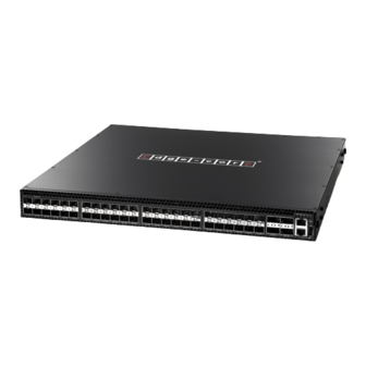
Installation Guide ECS5610-52S 48-Port 10G Top-of-Rack Switch with 48 10GBASE SFP+ Ports, 4 40GBASE QSFP+ Ports, 1 1000BASE-T (RJ-45) Management Port, 2 Power Supply Units (F2B and B2F Airflow), and 1 Fan Tray Module (F2B and B2F Airflow) E062013-KS-R01 150200000495A... -
Page 3: How To Use This Guide
How to Use This Guide This guide includes detailed information on the switch hardware, including network ports, power, cabling requirements, as well as plug-in modules and transceivers. This guide also provides general installation guidelines and recommended procedures. To deploy this switch effectively and ensure trouble- free operation, you should first read the relevant sections in this guide so that you are familiar with all its hardware components. - Page 4 How to Use This Guide ◆ Chapter 5 - Port Connections — Includes information on network interfaces, installing optional transceivers, and cabling specifications. ◆ Chapter 6 - Switch Management — Connecting to the switch for management, and information on the system status LEDs. ◆...
-
Page 5: Table Of Contents
Contents How to Use This Guide Contents Figures Tables 1 Switch Description Overview Key Hardware Components Key Technical Specifications Data Center Deployment Rack Cooling 2 Installation Overview Package Contents Switch Installation Tasks 3 Switch Chassis General Installation Guidelines How to Install the Switch in a Rack Rack-Mounting Items Rack-Mount Procedure Switch Cooling Requirements... - Page 6 Contents 5 Port Connections Cable Labeling and Connection Records Understanding the Port Status LEDs How to Install an SFP/SFP+/QSFP+ Transceiver How to Connect to the Twisted-Pair Copper Management Port Copper Cabling Guidelines 1000BASE-T Pin Assignments Connection Procedure How to Connect to SFP/SFP+ Fiber Optic Ports Connection Procedure How to Connect to QSFP+ Fiber Optic Ports Connection Procedure...
-
Page 7: Figures
Figures Figure 1: Front Panel Figure 2: Rear Panel Figure 3: Cloud Data Center Deployment Figure 4: Converged Ethernet Data Center Deployment Figure 5: F2B Airflow Cooling Figure 6: B2F Airflow Cooling Figure 7: Installing the Switch in a Rack Figure 8: Connecting AC Power Figure 9: System LEDs Figure 10: Console Port... - Page 8 Figures Figure 30: USB Port Figure 31: Reset Button – 8 –...
-
Page 9: Tables
Tables Table 1: Key Technical Specifications Table 2: Fan Tray Specifications Table 3: AC Power Supply Module Specifications Table 4: Maximum Twisted-Pair Copper Cable Lengths Table 5: 1000BASE-T MDI and MDI-X Port Pinouts Table 6: Maximum 10 Gigabit Ethernet Fiber Cable Lengths Table 7: Maximum Gigabit Ethernet Fiber Cable Lengths Table 8: Maximum 40 Gigabit Ethernet Fiber Cable Lengths Table 9: Maximum 10GBASE-CR 10 Gigabit Ethernet Cable Lengths... - Page 10 ◆ “Data Center Deployment” on page 14 Overview Thank you for choosing the ECS5610-52S switch system. This switch is built with leading-edge technology to deliver reliable high-performance connectivity for your data network. The ECS5610-52S switch is a high-performance top-of-rack switch, designed for data center operating environments.
-
Page 11: Switch Description Overview
Chapter 1 | Switch Description Overview Key Hardware The ECS5610-52S switch consists of several key hardware components. This manual describes each specific component, or related components, together with their Components installation requirements and procedures in each chapter. To understand each component in detail, refer to the relevant section. -
Page 12: Figure 2: Rear Panel
Chapter 1 | Switch Description Overview USB Port A USB port is provided on the switch front panel. This port is for transferring configuration files from a USB storage device to the switch’s flash memory. For more information, see “How to Connect to the USB Port” on page Reset Button Pressing the reset button on the front panel causes the switch to preform a hard reset. -
Page 13: Key Technical Specifications
Chapter 1 | Switch Description Key Technical Specifications Key Technical Specifications The following table contains key system specifications for the switch. Table 1: Key Technical Specifications Item Specification Ports 48 10 Gbps SFP+ transceiver slots 4 40 Gbps QSFP+ transceiver slots 1 10/100/1000 Mbps RJ-45 Management port Network Interface Ports 1~48: SFP+... -
Page 14: Data Center Deployment
Chapter 1 | Switch Description Data Center Deployment Data Center Deployment The switch is designed for high-availability data center environments with a high port density. The switch includes redundant, hot-swappable, load-sharing AC PSUs, a hot-swappable fan tray, and port-to-power and power-to-port airflow direction options. -
Page 15: Rack Cooling
Chapter 1 | Switch Description Data Center Deployment Figure 4: Converged Ethernet Data Center Deployment Core Switch Core Switch FCoE Storage Li nk Li nk Li nk Li nk Li nk Li nk Li nk Li nk Li nk Li nk Li nk Li nk Li nk... -
Page 16: Figure 6: B2F Airflow Cooling
Chapter 1 | Switch Description Data Center Deployment When mounted in a rack with other network equipment that may have a back-to- front (B2F) airflow direction, the top-of-rack switch includes power supply and fan tray modules that reverse the airflow direction through the switch. This enables various deployment options for the switch in the data center. - Page 17 Chapter 1 | Switch Description Data Center Deployment – 17 –...
-
Page 18: Installation Overview
Package Contents After unpacking the switch, check the contents to be sure you have received all the components. ◆ ECS5610-52S 10G Top-of-Rack Switch ◆ Rack Mounting Kit containing two brackets and eight screws for attaching the brackets to the switch ◆... -
Page 19: Switch Installation Tasks
Chapter 2 | Installation Overview Switch Installation Tasks Switch Installation Tasks Follow these tasks to install the switch in your network. For full details on each task, go to the relevant chapter or section by clicking on the link. Caution: Before installing your switch, first review all the safety statements and guidelines in the Regulatory and Safety Information document. -
Page 20: Figure 8: Connecting Ac Power
Chapter 2 | Installation Overview Switch Installation Tasks Task 3 Install Power Modules and Power On Install power modules, then power on. The switch supports up to two PSUs that have a matching airflow direction as the installed fan tray. Caution: The switch includes plug-in power supply and fan tray modules that are installed into its chassis. -
Page 21: Figure 9: System Leds
Chapter 2 | Installation Overview Switch Installation Tasks Figure 9: System LEDs System Status LEDs. Task 5 Make Initial Configuration Changes At this point you may need to make a few basic switch configuration changes before connecting to the network. It is suggested to connect to the switch console port to perform this task. -
Page 22: Figure 11: Making A Connection To A Qsfp+ Transceiver
Chapter 2 | Installation Overview Switch Installation Tasks For information on initial switch configuration: Refer to the Administrator’s Guide. Task 6 Install Transceivers and Connect Cables Install SFP+ or QSFP+ transceivers and connect network cables to port interfaces: ◆ Connect DAC cables to the SFP+/QSFP+ slots. Or first install SFP+/QSFP+ transceivers and then connect fiber optic cabling to the transceiver ports. -
Page 23: Switch Chassis
Switch Chassis The switch is designed to be installed in a standard 19-inch equipment rack. Before continuing with switch installation, first review the general guidelines and switch cooling requirements in this chapter. This chapter includes these sections: ◆ “General Installation Guidelines” on page 23 ◆... -
Page 24: How To Install The Switch In A Rack
Chapter 3 | Switch Chassis How to Install the Switch in a Rack How to Install the Switch in a Rack When rack mounting the switch, pay particular attention to the following factors: ◆ Rack Types: You can use any standard EIA 19-inch equipment rack with either two or four posts. -
Page 25: Figure 12: Attaching The Brackets
Chapter 3 | Switch Chassis How to Install the Switch in a Rack Attach the brackets to the device using the screws provided in the Rack Mounting Kit. Figure 12: Attaching the Brackets Use the screws provided in the Bracket Mounting Kit. -
Page 26: Switch Cooling Requirements
Chapter 3 | Switch Chassis Switch Cooling Requirements If installing a single switch only, go to “Power and Grounding” on page If installing multiple switches, repeat steps 1 to 4 to mount the switches following your rack plan. Switch Cooling Requirements Wherever the switch is located, be sure to pay close attention to switch cooling requirements. -
Page 27: Rack Cooling
Chapter 3 | Switch Chassis Switch Cooling Requirements Rack Cooling When mounting the switch in an enclosed rack or cabinet, be sure to check the following guidelines to prevent overheating: ◆ Make sure that enough cool air can flow into the enclosure for the equipment it contains. -
Page 28: How To Replace A Fan Tray
Chapter 3 | Switch Chassis Switch Cooling Requirements The following figure shows the fan tray removed from the switch. Figure 15: Fan Tray Label indicates airflow direction Table 2: Fan Tray Specifications Item Description Power Consumption 12 VDC @ 2.8 A, 37 Watts maximum Airflow 76.4 CFM minimum 90.4 CFM maximum... -
Page 29: Power And Grounding
If one power supply fails, the other power supply takes over the full load of the switch. The switch provides two AC power supply module options, which are listed below: ◆ ECS5610-52S-ACPWR (front-to-back airflow) ◆ ECS5610-52SR-ACPWR (back-to-front airflow) Caution: The switch includes plug-in power supply and fan tray modules that are installed into its chassis. -
Page 30: Figure 16: Ac Power Supply Module
Chapter 4 | Power and Grounding Power Supply Modules Figure 16: AC Power Supply Module AC Power Socket Release Lever Power Supply Module LED Label indicates airflow direction of PSU Table 3: AC Power Supply Module Specifications Item Description AC Input 100-240 VAC, 50-60 Hz, 6-3 A DC Output +5 Vsb @ 3 A... -
Page 31: Grounding The Chassis
Chapter 4 | Power and Grounding Grounding the Chassis Grounding the Chassis The switch chassis must be connected to ground to ensure proper operation and to meet electromagnetic interference (EMI) and safety requirements. The switch chassis is connected internally to 0 V, which is then grounded through an installed AC PSU when it is connected to a grounded AC power outlet by an AC power cord. -
Page 32: Figure 18: Ac Psu And Power Socket
Chapter 4 | Power and Grounding How to Connect to AC Power Figure 18: AC PSU and Power Socket AC Power Cord AC PSU Plug the power cord into a grounded, 3-pin, AC power source. Note: For international use, you may need to change the AC power cord. You must use a cord set that has been approved for the socket type in your country. -
Page 33: Port Connections
Port Connections This chapter focuses on making connections to switch network interfaces, including how to install optional transceivers, and details on network cable specifications. The switch features 48 SFP+ transceiver slots and four 40 Gigabit QSFP+ transceiver slots. The sections that follow describe these interfaces. Note: The switch also has one 10/100/1000BASE-T port for dedicated management access. -
Page 34: Cable Labeling And Connection Records
Chapter 5 | Port Connections Cable Labeling and Connection Records Cable Labeling and Connection Records When planning a network installation, it is essential to label the opposing ends of cables and to record where each cable is connected. Doing so will enable you to easily locate inter-connected devices, isolate faults and change your topology without need for unnecessary time consumption. -
Page 35: Understanding The Port Status Leds
Chapter 5 | Port Connections Understanding the Port Status LEDs Understanding the Port Status LEDs The switch includes LED indicators for each port to indicate link status and network activity. The port LEDs are shown below and described in the following table. Figure 19: Port Status LEDs Port 1-48 Link/Activity LEDs Port 49-52 Link/Activity LEDs... -
Page 36: How To Install An Sfp/Sfp+/Qsfp+ Transceiver
Chapter 5 | Port Connections How to Install an SFP/SFP+/QSFP+ Transceiver How to Install an SFP/SFP+/QSFP+ Transceiver The switch provides slots for optional SFP, SFP+, and QSFP+ transceivers. The supported transceiver types are listed below: ◆ 40 Gbps Ethernet QSFP+ transceivers 40GBASE-CR4 ■... -
Page 37: How To Connect To The Twisted-Pair Copper Management Port
Chapter 5 | Port Connections How to Connect to the Twisted-Pair Copper Management Port Figure 21: Inserting an SFP/SFP+/QSFP+ Transceiver into a Slot QSFP+ Transceiver Note: To uninstall a transceiver: First disconnect the network cable, then release and pull the wire bail to remove the transceiver from the slot. How to Connect to the Twisted-Pair Copper Management Port The RJ-45 management port on the switch supports automatic MDI/MDI-X pinout configuration, so you can use standard straight-through twisted-pair cables to... -
Page 38: Copper Cabling Guidelines
Chapter 5 | Port Connections How to Connect to the Twisted-Pair Copper Management Port Copper Cabling To ensure proper operation when installing the switch into a network, make sure Guidelines that the current cable is suitable for 10BASE-T, 100BASE-TX or 1000BASE-T operation. -
Page 39: Connection Procedure
Chapter 5 | Port Connections How to Connect to SFP/SFP+ Fiber Optic Ports Table 5: 1000BASE-T MDI and MDI-X Port Pinouts (Continued) MDI Signal Name MDI-X Signal Name Bi-directional Pair B Plus (BI_DB+) Bi-directional Pair A Plus (BI_DA+) Bi-directional Pair C Plus (BI_DC+) Bi-directional Pair D Plus (BI_DD+) Bi-directional Pair C Minus (BI_DC-) Bi-directional Pair D Minus (BI_DD-) -
Page 40: Connection Procedure
Chapter 5 | Port Connections How to Connect to SFP/SFP+ Fiber Optic Ports Table 6: Maximum 10 Gigabit Ethernet Fiber Cable Lengths (Continued) Fiber Size Fiber Bandwidth Maximum Cable Length Connector 10GBASE-LRM 62.5/125 micron multimode 220 m (722 ft.) 50/125 micron multimode 220 m (722 ft.) 9/125 micron single-mode 300 m (722 ft.) -
Page 41: Figure 23: Making Connections To An Sfp+ Transceiver
Chapter 5 | Port Connections How to Connect to SFP/SFP+ Fiber Optic Ports Check that the fiber terminators are clean. You can clean the cable plugs by wiping them gently with a clean tissue or cotton ball moistened with a little ethanol. -
Page 42: How To Connect To Qsfp+ Fiber Optic Ports
Chapter 5 | Port Connections How to Connect to QSFP+ Fiber Optic Ports How to Connect to QSFP+ Fiber Optic Ports The switch includes four slots for 40 Gigabit Ethernet QSFP+ fiber-optic transceivers. Note that 40G fiber optic ports can provide either one 40 Gbps full- duplex link, four independent 10G fiber optic links. -
Page 43: Figure 24: Connecting To A Qsfp+ Transceiver
Chapter 5 | Port Connections How to Connect to QSFP+ Fiber Optic Ports Connect one end of the cable to the QSFP+ port on the switch and the other end to the QSFP+ port on the other device. Since QSFP+ connectors are keyed, the cable can only be attached in the correct orientation. -
Page 44: Dac Connections
Chapter 5 | Port Connections DAC Connections DAC Connections Direct Attach Cable (DAC) is a method of connecting two SFP+/QSFP+ interfaces without using optics and fiber cable. A fixed length of twinax copper cable is terminated at each end with physically-compliant SFP+/QSFP+ transceivers that do not include all their normal electronic and optical components. -
Page 45: Figure 25: Making Dac Connections
Chapter 5 | Port Connections DAC Connections Figure 25: Making DAC Connections 10G SFP+ DAC Cable Plug the other end of the twinax cable into an SFP+/QSFP+ slot on the switch. Check that the Link LED on the switch turns on green to indicate that the connection is valid. - Page 46 Chapter 5 | Port Connections DAC Connections – 46 –...
-
Page 47: Switch Management
Switch Management The switch includes a management agent that allows you to configure or monitor the switch using its embedded management software. To manage the switch, you can make a direct connection to the console port (out-of-band), or you can manage it through a network connection (in-band) using Telnet, Secure Shell (SSH), a web browser, or SNMP-based network management software. -
Page 48: Understanding The System Status Leds
Chapter 6 | Switch Management Understanding the System Status LEDs Understanding the System Status LEDs The switch includes a display panel of key system LED indicators. The LEDs, which are located on the front panel, are shown below and described in the following table. -
Page 49: How To Connect To The Management Port
Chapter 6 | Switch Management How to Connect to the Management Port How to Connect to the Management Port The 10/100/1000BASE-T port labeled “Mgmt” provides a dedicated management interface which is segregated from the data traffic crossing the other ports. This port supports auto-negotiation, so the optimum transmission mode (half or full duplex) and data rate (10, 100, or 1000 Mbps) can be selected automatically, if this feature is also supported by the attached device. -
Page 50: How To Connect To The Console Port
Chapter 6 | Switch Management How to Connect to the Console Port Follow these steps to connect to the Management port: Attach one end of a twisted-pair cable to an RJ-45 connector on a management network device (PC or another switch). Attach the other end of the twisted-pair cable to the Management port on the switch. -
Page 51: Figure 29: Console Port Connection
Chapter 6 | Switch Management How to Connect to the Console Port The following table describes the pin assignments used in the RJ-45-to-DB-9 console cable. Table 13: Console Cable Wiring Switch’s 8-Pin Null Modem PC’s 9-Pin Console Port DTE Port 6 RXD (receive data) <--------------------- 3 TXD (transmit data) -
Page 52: How To Connect To The Usb Port
Chapter 6 | Switch Management How to Connect to the USB Port Attach the RJ-45 end of the serial cable to the Console port on the switch. Configure the PC’s COM port required settings using VT-100 terminal emulator software (such as HyperTerminal) running on the management PC. Log in to the command-line interface (CLI) using default settings: User —... -
Page 53: How To Reset The Switch
Chapter 6 | Switch Management How to Reset the Switch How to Reset the Switch The Reset button on the switch can be used to restart the device and set the configuration back to factory default values. Use a long thin object, such as the end of a paperclip, to depress the Reset button. One push of the button restarts the system software using default values. -
Page 54: A Troubleshooting
Troubleshooting Diagnosing LED Indicators Table 14: Troubleshooting Chart Symptom Action ◆ PSU1/PSU2 LED is Off Check connections between the PSU, the power cord and the wall outlet. ◆ Contact your dealer for assistance. ◆ PSU1/PSU2 LED is on Power cycle the PSU to try and clear the condition. Amber ◆... -
Page 55: Power And Cooling Problems
Chapter A | Troubleshooting Power and Cooling Problems Power and Cooling Problems If a power indicator does not turn on when the power cord is plugged in, you may have a problem with the power outlet, power cord, or PSU. However, if the switch powers off after running for a while, check for loose power connections, power losses or surges at the power outlet. -
Page 56: Index
Index Numerics installation power requirements 1000BASE-SX fiber cable Lengths site requirements 1000BASE-T PIN assignments installation troubleshooting 10GBASE fiber cable lengths introduction 10GBASE-LR fiber cable lengths laser safety air flow requirements LC port connections LED indicators DIAG port brackets, attaching power buffer size location requirements cable... - Page 57 Index site selelction specifications environmental status LEDs surge suppressor, using web-based management – 57 –...
- Page 58 Declaration of Conformity (DoC) can be obtained from www.edge-core.com -> support -> download -> declarations & certifications ECS5610-52S E062013-KS-R01 150200000495A...
Need help?
Do you have a question about the ECS5610-52S and is the answer not in the manual?
Questions and answers