Table of Contents
Advertisement
Quick Links
Quick Star t Guide
10/28-Port Web-Smart Pro Gigabit Ethernet Switch
ECS2100-10T/ECS2100-10P/ECS2100-10PE
ECS2100-28T/ECS2100-28P/ECS2100-28PP
ECS2100-10T
ECS2100-10PE
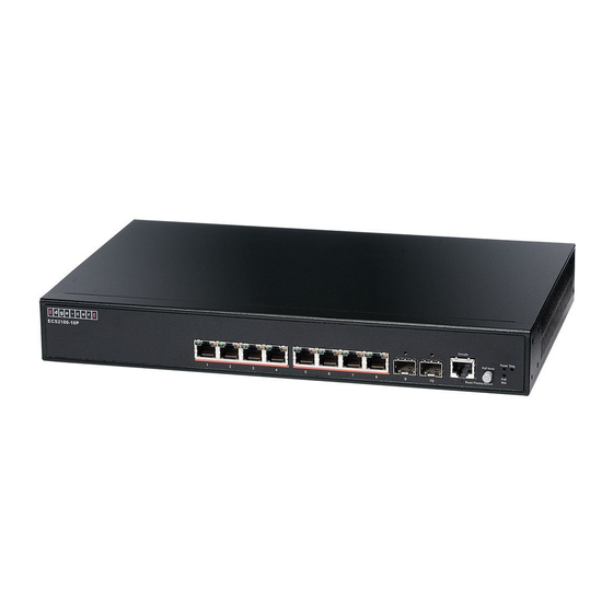
ECS2100-10P
ECS2100-28T
ECS2100-28P
ECS2100-28PP
www.edge-core.com
The ECS2100 series switches include the following models:
ECS2100-10T— 8 10/100/1000BASE-T + 2 SFP uplink ports
ECS2100-10PE— 8 10/100/000BASE-T + 2 SFP uplink ports (4 PoE ports)
ECS2100-10P— 8 10/100/1000BASE-T + 2 SFP uplink ports (8 PoE ports)
ECS2100-28T— 24 10/100/000BASE-T + 4 SFP uplink ports
ECS2100-28P— 24 10/100/000BASE-T + 4 SFP uplink ports (24 PoE ports)
ECS2100-28PP— 24 10/100/000BASE-T + 4 SFP uplink ports (24 PoE ports)
N
:
The ECS2100 series switches are for indoor use only.
OTE
N
:
For Safety and Regulatory information, refer to the Safety and Regulatory
OTE
Information document included with the switch.
– 1 –
E012016-AP-R01
150200001318A
Advertisement
Table of Contents

Related Manuals for Edge-Core ECS2100 Series


Summary of Contents for Edge-Core ECS2100 Series
- Page 1 ECS2100-28PP— 24 10/100/000BASE-T + 4 SFP uplink ports (24 PoE ports) ECS2100-10T ECS2100-10PE ECS2100-10P ECS2100-28T ECS2100-28P ECS2100-28PP The ECS2100 series switches are for indoor use only. For Safety and Regulatory information, refer to the Safety and Regulatory Information document included with the switch. E012016-AP-R01 www.edge-core.com – 1 – 150200001318A...
- Page 2 Console cable—RJ-45 to DB-9 Note: For other documentations include Installation Guide, Web Management Guide, and CLI Reference Guide can be obtained from www.edge-core.com -> support -> download -> user manual. 2. Install the Switch Rack Mounting The switch can be mounted in a standard 19-inch rack or on a desktop or shelf.
- Page 3 Quick Start Guide Set two screws in the wall 150 mm (5.9 in.) apart. Slide the switch’s wall mounting slots down onto the screws so that the unit is secure. 3. Ground the Switch Before powering on the switch, ground the switch to earth. Ensure the rack on which the switch is to be mounted is properly grounded and in compliance with ETSI ETS 300 253.
- Page 4 Quick Start Guide Plug the AC power cord into the socket on the rear of the switch. The ECS2100-10PE includes an AC-DC power adapter. Connect the AC-DC power adapter to the switch and to an AC power source. The AC-DC adapter provides 54 VDC, 1.67 A of power to the switch.
- Page 5 Quick Start Guide 6. Make Initial At this point, you may need to make a few basic switch configuration changes before connecting to the network. you can either connect to the switch console Configuration port or any RJ-45 port to perform this task. Changes Through an RJ-45 Port The switch offers a user-friendly web-based management interface for the...
- Page 6 Quick Start Guide 7. Connect Network Install SFP transceivers and connect network cables to port interfaces: Cables ◆ For RJ-45 ports, use 100-ohm Category 5, 5e or better twisted-pair cable for 1000BASE-T connections, Category 5 or better for 100BASE-TX connections, and Category 3 or better for 10BASE-T connections.
-
Page 7: Quick Start Guide
Quick Start Guide — Extended Power Supply EPS460W Install the ECS2100-28PP in a standard 19-inch rack and power on. Install the PS3000 chassis in a standard 19-inch rack. Install one or more EPS460W PSUs in the chassis. The chassis can support up to three EPS460W PSUs. -
Page 8: Hardware Specifications
Quick Start Guide Hardware Specifications Item Specification Chassis Specifications Size (W x D x H): ECS2100-10T: 19.64 x 11.71 x 3.66 cm (7.73 x 4.61 x 1.44 in.) ECS2100-10P: 33.0 x 20.4 x 4.26 cm (12.99 x 8.03 x 1.67 in.) ECS2100-10PE: 24.0 x 15.5 x 2.65 cm (9.44 x 6.10 x 1.04 in.) ECS2100-28T/28P/28PP: 44 x 22 x 4.4 cm (17.32 x 8.66 x 1.73 in.
Need help?
Do you have a question about the ECS2100 Series and is the answer not in the manual?
Questions and answers