Advertisement
Available languages
Available languages
Quick Links
Advertisement

Subscribe to Our Youtube Channel
Related Manuals for Edge-Core ECS5510-48S


Summary of Contents for Edge-Core ECS5510-48S
- Page 1 ECS5510-48S Installation Guide 48-Port 10G Ethernet Top-of-Rack Switch www.edge-core.com...
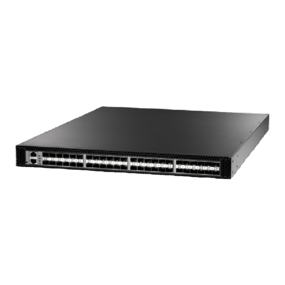
- Page 3 NSTALLATION UIDE ECS5510-48S (F2B) 10G E THERNET WITCH Layer 2 Switch with 48 10GBASE SFP+ Slots, one Power Supply Unit (F2B Airflow), and one Fan Tray Module (F2B Airflow) ECS5510-48S (B2F) 10G E THERNET WITCH Layer 2 Switch with 48 10GBASE SFP+ Slots,...
- Page 5 OMPLIANCES AND AFETY TATEMENTS FCC - C LASS This equipment has been tested and found to comply with the limits for a Class A digital device, pursuant to part 15 of the FCC Rules. These limits are designed to provide reasonable protection against harmful interference when the equipment is operated in a commercial environment.
- Page 6 OMPLIANCES AND AFETY TATEMENTS CE M (EEC) ECLARATION OF ONFORMANCE FOR AFETY This information technology equipment complies with the requirements of the Council Directive 89/336/EEC on the Approximation of the laws of the Member States relating to Electromagnetic Compatibility and 73/23/EEC for electrical equipment used within certain voltage limits and the Amendment Directive 93/ 68/EEC.
- Page 7 OMPLIANCES AND AFETY TATEMENTS AFETY OMPLIANCE Warning: Fiber Optic Port Safety When using a fiber optic port, never look at the transmit laser while it is powered on. Also, never look directly at the fiber TX port and fiber CLASS I cable ends when they are powered on.
- Page 8 OMPLIANCES AND AFETY TATEMENTS OWER AFETY Please read the following safety information carefully before installing the switch: Installation and removal of the unit must be carried out by qualified WARNING: personnel only. The unit must be connected to an earthed (grounded) outlet to comply with ◆...
- Page 9 OMPLIANCES AND AFETY TATEMENTS Power Cord Set U.S.A. and Canada The cord set must be UL-approved and CSA certified. The minimum specifications for the flexible cord are: - No. 18 AWG - not longer than 2 meters, or 16 AWG. - Type SV or SJ - 3-conductor The cord set must have a rated current capacity of at least 10 A...
- Page 10 OMPLIANCES AND AFETY TATEMENTS La prise secteur doit se trouver à proximité de l’appareil et son accès doit ◆ être facile. Vous ne pouvez mettre l’appareil hors circuit qu’en débranchant son cordon électrique au niveau de cette prise. L’appareil fonctionne à une tension extrêmement basse de sécurité qui est ◆...
- Page 11 OMPLIANCES AND AFETY TATEMENTS Bitte unbedingt vor dem Einbauen des Switches die folgenden Sicherheitsanweisungen durchlesen: Die Installation und der Ausbau des Geräts darf nur durch WARNUNG: Fachpersonal erfolgen. Das Gerät sollte nicht an eine ungeerdete Wechselstromsteckdose ◆ angeschlossen werden. Das Gerät muß an eine geerdete Steckdose angeschlossen werden, welche ◆...
- Page 12 OMPLIANCES AND AFETY TATEMENTS ARNINGS AND AUTIONARY ESSAGES This product does not contain any serviceable user parts. ARNING Installation and removal of the unit must be carried out by ARNING qualified personnel only. When connecting this device to a power outlet, connect the ARNING field ground lead on the tri-pole power plug to a valid earth ground line to prevent electrical hazards.
- Page 13 OMPLIANCES AND AFETY TATEMENTS ND OF RODUCT This product is manufactured in such a way as to allow for the recovery and disposal of all included electrical components once the product has reached the end of its life. ANUFACTURING ATERIALS There are no hazardous nor ozone-depleting materials in this product.
- Page 14 OMPLIANCES AND AFETY TATEMENTS – 14 –...
- Page 15 BOUT UIDE URPOSE This guide details the hardware features of the switch, including the physical and performance-related characteristics, and how to install the switch. UDIENCE The guide is intended for use by network administrators who are responsible for installing and setting up network equipment; consequently, it assumes a basic working knowledge of LANs (Local Area Networks).
- Page 16 BOUT UIDE EVISION ISTORY This section summarizes the changes in each revision of this guide. 2010 R OVEMBER EVISION This is the first revision of this guide. – 16 –...
- Page 17 ONTENTS OMPLIANCES AND AFETY TATEMENTS BOUT UIDE ONTENTS ABLES IGURES NTRODUCTION Overview Switch Architecture Network Management Options Data Center Deployment Description of Hardware SFP+ Transceiver Slots RJ-45 Management Port Console Port Reset Button Port and System Status LEDs Power Supply Modules Fan Tray Module NSTALLING THE WITCH...
- Page 18 ONTENTS Rack Mounting Horizontal Surface Mounting Installing an Optional SFP/SFP+ Transceiver Connecting to a Power Source Connecting to the Console Port Wiring Map for Serial Cable AKING ETWORK ONNECTIONS Twisted-Pair Connections Cabling Guidelines Connecting to the Management Port DAC Connections Making 10GBASE-CR DAC Connections Fiber Optic Connections Connectivity Rules...
- Page 19 ONTENTS Straight-Through Wiring Crossover Wiring 1000BASE-T Pin Assignments Fiber Standards PECIFICATIONS Physical Characteristics Power Supply Module Switch Features Management Features Standards Compliances LOSSARY NDEX – 19 –...
- Page 20 ONTENTS – 20 –...
Need help?
Do you have a question about the ECS5510-48S and is the answer not in the manual?
Questions and answers