
Subscribe to Our Youtube Channel
Related Manuals for Edge-Core ECS3510-52T


Summary of Contents for Edge-Core ECS3510-52T
- Page 1 ECS3510-52T Installation Guide 52-Port Layer 2 Fast Ethernet Switch www.edge-core.com...
- Page 3 N S T A L L A T I O N U I D E ECS3510-52T L AYER THERNET WITCH Layer 2 Switch with 48 10/100BASE-TX (RJ-45) Ports, and 4 Combination Gigabit (RJ-45/SFP) Ports ECS3510-52T E122012-CS-R01 150200000507A...
-
Page 5: Compliances And Safety Statements
OMPLIANCES AND AFETY TATEMENTS FCC - C LASS This equipment has been tested and found to comply with the limits for a Class A digital device, pursuant to part 15 of the FCC Rules. These limits are designed to provide reasonable protection against harmful interference when the equipment is operated in a commercial environment. - Page 6 OMPLIANCES AND AFETY TATEMENTS CE M (EEC) ECLARATION OF ONFORMANCE FOR AFETY This information technology equipment complies with the requirements of the Council Directive 204/108/EC on the Approximation of the laws of the Member States relating to Electromagnetic Compatibility and 2006/95/EC for electrical equipment used within certain voltage.
- Page 7 OMPLIANCES AND AFETY TATEMENTS AFETY OMPLIANCE Warning: Fiber Optic Port Safety When using a fiber optic port, never look at the transmit laser while it is powered on. Also, never look directly at the fiber TX port and fiber CLASS I cable ends when they are powered on.
- Page 8 OMPLIANCES AND AFETY TATEMENTS ◆ 如果電源供應器已損壞,請不要嘗試自行修復。請將之交給專業技術服務人員或經銷商 來處理。 操作方面的安全性 ◆ 在使用產品之前,請確定所有的排線、電源線都已正確地連接好。若您發現有重大的瑕 疵,請盡速連絡您的經銷商。 ◆ 為避免發生電氣短路情形,請務必將所有沒用到的螺絲、迴紋針及其他零件收好,不要 遺留在主機板上或產品主機中。 ◆ 灰塵、溼氣以及劇烈的溫度變化都會影響主機板的使用壽命,因此請盡量避免放置在這 些地方。 ◆ 請勿將產品主機放置在容易搖晃的地方。 ◆ 若在本產品的使用上有任何的技術性問題,請和經過檢定或有經驗的技術人員聯絡。 使用注意事項 ◆ 在您開始操作本系統之前,請務必詳閱以下注意事項,以避免因為人為的疏失造成系統 損傷甚至人體本身的安全。 ◆ 使用前,請檢查產品各部份組件是否正常,以及電源線是否有任破損,或是連接不正確 的情形發生。 ◆ 如果有任何破損情形,請盡速與您的授權經銷商連絡,更換良好的線路。 ◆ 產品放置的位置請遠離灰塵過多,溫度過高,太陽直射的地方。 ◆ 保持機器在乾燥的環境下使用,雨水、溼氣、液體等含有礦物質將會腐蝕電子線路。 ◆ 使用時,請務必保持周遭散熱空間,以利散熱。 ◆ 使用前,請檢查各項周邊設備是否都已經連接妥當再開機。 ◆ 避免邊吃東西邊使用,以免污染機件造成故障。 ◆...
- Page 9 OMPLIANCES AND AFETY TATEMENTS OWER AFETY Please read the following safety information carefully before installing the switch: Installation and removal of the unit must be carried out by qualified WARNING: personnel only. The unit must be connected to an earthed (grounded) outlet to comply with ◆...
- Page 10 OMPLIANCES AND AFETY TATEMENTS Power Cord Set U.S.A. and Canada The cord set must be UL-approved and CSA certified. The minimum specifications for the flexible cord are: - No. 18 AWG - not longer than 2 meters, or 16 AWG. - Type SV or SJ - 3-conductor The cord set must have a rated current capacity of at least 10 A...
- Page 11 OMPLIANCES AND AFETY TATEMENTS La prise secteur doit se trouver à proximité de l’appareil et son accès doit ◆ être facile. Vous ne pouvez mettre l’appareil hors circuit qu’en débranchant son cordon électrique au niveau de cette prise. L’appareil fonctionne à une tension extrêmement basse de sécurité qui est ◆...
- Page 12 OMPLIANCES AND AFETY TATEMENTS Bitte unbedingt vor dem Einbauen des Switches die folgenden Sicherheitsanweisungen durchlesen: Die Installation und der Ausbau des Geräts darf nur durch WARNUNG: Fachpersonal erfolgen. Das Gerät sollte nicht an eine ungeerdete Wechselstromsteckdose ◆ angeschlossen werden. Das Gerät muß an eine geerdete Steckdose angeschlossen werden, welche ◆...
- Page 13 OMPLIANCES AND AFETY TATEMENTS ARNINGS AND AUTIONARY ESSAGES This product does not contain any serviceable user parts. ARNING Installation and removal of the unit must be carried out by ARNING qualified personnel only. When connecting this device to a power outlet, connect the ARNING field ground lead on the tri-pole power plug to a valid earth ground line to prevent electrical hazards.
- Page 14 OMPLIANCES AND AFETY TATEMENTS ND OF RODUCT This product is manufactured in such a way as to allow for the recovery and disposal of all included electrical components once the product has reached the end of its life. ANUFACTURING ATERIALS There are no hazardous nor ozone-depleting materials in this product.
-
Page 15: About This Guide
BOUT UIDE URPOSE This guide details the hardware features of the switch, including the physical and performance-related characteristics, and how to install the switch. UDIENCE The guide is intended for use by network administrators who are responsible for installing and setting up network equipment; consequently, it assumes a basic working knowledge of LANs (Local Area Networks). - Page 16 BOUT UIDE EVISION ISTORY This section summarizes the changes in each revision of this guide. 2012 R ECEMBER EVISION This is the first revision of this guide. – 16 –...
-
Page 17: Table Of Contents
ONTENTS OMPLIANCES AND AFETY TATEMENTS BOUT UIDE ONTENTS ABLES IGURES NTRODUCTION Overview Switch Architecture Network Management Options Description of Hardware 10/100BASE-T Ports SFP Slots Port and System Status LEDs Power Supply Socket Application Examples Network Aggregation Plan Remote Connection with Fiber Cable NSTALLING THE WITCH Selecting a Site... - Page 18 ONTENTS Rack Mounting Desktop or Shelf Mounting Installing an Optional SFP Transceiver Connecting to a Power Source Connecting to the Console Port Wiring Map for Serial Cable AKING ETWORK ONNECTIONS Connecting Network Devices Twisted-Pair Devices Cabling Guidelines Connecting to PCs, Servers, Hubs and Switches Network Wiring Connections Fiber Optic SFP Devices Connectivity Rules...
- Page 19 ONTENTS Fiber Standards PECIFICATIONS Physical Characteristics Switch Features Management Features Standards Compliances LOSSARY NDEX – 19 –...
- Page 20 ONTENTS – 20 –...
-
Page 21: Tables
ABLES Table 1: Port Status LEDs Table 2: System Status LEDs Table 3: Console Cable Wiring Table 4: Maximum 1000BASE-T Gigabit Ethernet Cable Length Table 5: Maximum 1000BASE-SX Gigabit Ethernet Cable Lengths Table 6: Maximum 1000BASE-LX Gigabit Ethernet Cable Length Table 7: Maximum 1000BASE-LH Gigabit Ethernet Cable Length Table 8:... - Page 22 ABLES – 22 –...
-
Page 23: Figures
IGURES Figure 1: Front Panel Figure 2: Rear Panel Figure 3: Port and System Status LEDs Figure 4: Power Supply Socket Figure 5: Network Aggregation Plan Figure 6: Remote Connections with Fiber Cable Figure 7: RJ-45 Plug Figure 8: Attaching the Brackets Figure 9: Installing the Switch in a Rack Figure 10:... - Page 24 IGURES – 24 –...
-
Page 25: Introduction
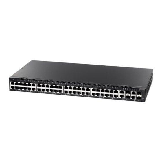
NTRODUCTION VERVIEW The ECS3510-52T switch is a intelligent switch with 48 10/100BASE-T ports, and four Gigabit combination ports that are comprised of an RJ-45 port and an SFP transceiver slot. There is also an SNMP-based management agent embedded on the main board. This agent supports both in-band and out-of-band access for managing the switch. -
Page 26: Switch Architecture
| Introduction HAPTER Overview Figure 2: Rear Panel Console Power Socket Port WITCH RCHITECTURE This switch employs a wire-speed, non-blocking switching fabric. This permits simultaneous wire-speed transport of multiple packets at low latency on all ports. This switch also features full-duplex capability on all ports, which effectively doubles the bandwidth of each connection. -
Page 27: Description Of Hardware
| Introduction HAPTER Description of Hardware ESCRIPTION OF ARDWARE 10/100BASE-T P ORTS This switch contains 48 RJ-45 ports that operate at 10 Mbps or 100 Mbps, half or full duplex. Because all ports on both switches support automatic MDI/MDI-X operation, you can use straight-through cables for all network connections to PCs or servers, or to other switches or hubs. -
Page 28: Table 1: Port Status Leds
| Introduction HAPTER Description of Hardware Figure 3: Port and System Status LEDs Combination Gigabit Port Status LEDs RJ-45 Port Status LEDs System Status LEDs Table 1: Port Status LEDs Condition Status RJ-45 Ports (1-48) Link/Activity On/Blinking Green The port has a valid 10 or 100 Mbps link. Blinking indicates activity. -
Page 29: Power Supply Socket
| Introduction HAPTER Application Examples OWER UPPLY OCKET There is one standard power socket on the rear panel of the switch for the AC power cord. Figure 4: Power Supply Socket Power Socket PPLICATION XAMPLES This switch is an excellent choice for mixed Ethernet, Fast Ethernet, and Gigabit Ethernet installations where significant growth is expected in the near future. -
Page 30: Remote Connection With Fiber Cable
| Introduction HAPTER Application Examples Figure 5: Network Aggregation Plan 1000 Mbps 10/100 Mbps Server Farm 10/100 Mbps Segments 10/100 Mbps Segments EMOTE ONNECTION WITH IBER ABLE Fiber optic technology allows for longer cabling than any other media type. A 1000BASE-SX (MMF) link can connect to a site up to 550 meters away, a 1000BASE-LX (SMF) link up to 10 km, and a 1000BASE-LH link up to 70 km. -
Page 31: Figure 6: Remote Connections With Fiber Cable
| Introduction HAPTER Application Examples Figure 6: Remote Connections with Fiber Cable 1000 Mbps 10/100 Mbps Server Farm 1000BASE-LX SMF (10 km) 1000BASE-SX MMF (550 m) Remote Switch Remote Switch 10/100 Mbps Segments 10/100 Mbps Segments – 31 –... - Page 32 | Introduction HAPTER Application Examples – 32 –...
-
Page 33: Installing The Switch
NSTALLING THE WITCH ELECTING A Switch units can be mounted in a standard 19-inch equipment rack or on a flat surface. Be sure to follow the guidelines below when choosing a location. The site should: ◆ be at the center of all the devices you want to link and near a power ■... -
Page 34: Ethernet Cabling
| Installing the Switch HAPTER Ethernet Cabling THERNET ABLING To ensure proper operation when installing the switch into a network, make sure that the current cables are suitable for 10BASE-T, 100BASE-TX or 1000BASE-T operation. Check the following criteria against the current installation of your network: Cable type: Unshielded twisted pair (UTP) or shielded twisted pair (STP) ◆... -
Page 35: Equipment Checklist
Then, before beginning the installation, be sure you have all other necessary installation equipment. ACKAGE ONTENTS ECS3510-52T L2 Fast Ethernet Switch ◆ Four adhesive foot pads ◆ Bracket Mounting Kit containing two brackets and eight screws for attaching ◆... -
Page 36: Mounting
| Installing the Switch HAPTER Mounting OUNTING The switch units can be mounted in a standard 19-inch equipment rack or on a desktop or shelf. Mounting instructions for each type of site follow. OUNTING Before rack mounting the switch, pay particular attention to the following factors: Temperature: Since the temperature within a rack assembly may be ◆... -
Page 37: Figure 8: Attaching The Brackets
| Installing the Switch HAPTER Mounting Figure 8: Attaching the Brackets Mount the device in the rack, using four rack-mounting screws (not provided). Figure 9: Installing the Switch in a Rack If installing a single switch only, go to “Connecting to a Power Source” on page –... -
Page 38: Desktop Or Shelf Mounting
| Installing the Switch HAPTER Mounting If installing multiple switches, mount them in the rack, one below the other, in any order. ESKTOP OR HELF OUNTING Attach the four adhesive feet to the bottom of the first switch. Figure 10: Attaching the Adhesive Feet Set the device on a flat surface near an AC power source, making sure there are at least two inches of space on all sides for proper air flow. -
Page 39: Installing An Optional Sfp Transceiver
| Installing the Switch HAPTER Installing an Optional SFP Transceiver SFP T NSTALLING AN PTIONAL RANSCEIVER Figure 11: Inserting an SFP Transceiver into a Slot The switch supports 1000BASE-SX, 1000BASE-LX, 1000BASE-LH and other SFP- compatible transceivers. To install an SFP transceiver, do the following: Consider network and cabling requirements to select an appropriate SFP transceiver type. -
Page 40: Connecting To A Power Source
| Installing the Switch HAPTER Connecting to a Power Source ONNECTING TO A OWER OURCE To connect a device to a power source: Insert the power cable plug directly into the socket located at the back of the device. Figure 12: Power Sockets Plug the other end of the cable into a grounded, 3-pin socket. -
Page 41: Connecting To The Console Port
| Installing the Switch HAPTER Connecting to the Console Port ONNECTING TO THE ONSOLE The DB-9 serial port on the switch’s front panel is used to connect to the switch for out-of-band console configuration. The on-board configuration program can be accessed from a terminal or a PC running a terminal emulation program. The pin assignments used to connect to the serial port are described in the following figure and table. - Page 42 | Installing the Switch HAPTER Connecting to the Console Port The serial port’s configuration requirements are as follows: Default Baud rate—115,200 bps ◆ Character Size—8 Characters ◆ Parity—None ◆ Stop bit—One ◆ Data bits—8 ◆ – 42 –...
-
Page 43: Making Network Connections
AKING ETWORK ONNECTIONS ONNECTING ETWORK EVICES This switch is designed to interconnect multiple segments (or collision domains). It can be connected to network cards in PCs and servers, as well as to hubs, switches or routers. It may also be connected to devices using optional SFP tranceivers. -
Page 44: Connecting To Pcs, Servers, Hubs And Switches
| Making Network Connections HAPTER Twisted-Pair Devices ONNECTING TO ERVERS UBS AND WITCHES Attach one end of a twisted-pair cable segment to the device’s RJ-45 connector. Figure 14: Making Twisted-Pair Connections If the device is a PC card and the switch is in the wiring closet, attach the other end of the cable segment to a modular wall outlet that is connected to the wiring closet. -
Page 45: Network Wiring Connections
| Making Network Connections HAPTER Twisted-Pair Devices ETWORK IRING ONNECTIONS Today, the punch-down block is an integral part of many of the newer equipment racks. It is actually part of the patch panel. Instructions for making connections in the wiring closet with this type of equipment follows. Attach one end of a patch cable to an available port on the switch, and the other end to the patch panel. -
Page 46: Fiber Optic Sfp Devices
| Making Network Connections HAPTER Fiber Optic SFP Devices SFP D IBER PTIC EVICES An optional Gigabit SFP transceiver (1000BASE-SX, 1000BASE-LX, or 1000BASE-LH) can be used for a backbone connection between switches, or for connecting to a high-speed server. Each multimode fiber optic port requires 50/125 or 62.5/125 micron multimode fiber optic cabling with an LC connector at both ends. -
Page 47: Connectivity Rules
| Making Network Connections HAPTER Connectivity Rules Figure 16: Making Fiber Port Connections As a connection is made, check the Link LED on the switch corresponding to the port to be sure that the connection is valid. The 1000BASE-SX, 1000BASE-LX and 1000BASE-LH fiber optic ports operate at 1 Gbps full duplex, with auto-negotiation of flow control. -
Page 48: 1000 Mbps Gigabit Ethernet Collision Domain
| Making Network Connections HAPTER Connectivity Rules Category 5e (enhanced Category 5) or Category 6 cable should be used. The Category 5e specification includes test parameters that are only recommendations for Category 5. Therefore, the first step in preparing existing Category 5 cabling for running 1000BASE-T is a simple test of the cable installation to be sure that it complies with the IEEE 802.3ab standards. -
Page 49: 100 Mbps Fast Ethernet Collision Domain
| Making Network Connections HAPTER Cable Labeling and Connection Records 100 M THERNET OLLISION OMAIN Table 8: Maximum Fast Ethernet Cable Lengths Type Cable Type Max. Cable Length Connector 100BASE-TX Category 5 or better 100-ohm 100 m (328 ft) RJ-45 UTP or STP 10 M THERNET... - Page 50 | Making Network Connections HAPTER Cable Labeling and Connection Records Label each separate piece of equipment. ◆ Display a copy of your equipment map, including keys to all abbreviations at ◆ each equipment rack. – 50 –...
-
Page 51: Diagnosing Switch Indicators
ROUBLESHOOTING IAGNOSING WITCH NDICATORS Table 10: Troubleshooting Chart Symptom Action Pwr LED is Off ◆ Power supply is disconnected. ◆ Check connections between the switch, the power cord, and the wall outlet. ◆ Contact your dealer for assistance. Diag LED is Off ◆... -
Page 52: Troubleshooting
| Troubleshooting PPENDIX Power and Cooling Problems OWER AND OOLING ROBLEMS If the power indicator does not turn on when the power cord is plugged in, you may have a problem with the power outlet, power cord, or internal power supply. -
Page 53: Cables
ABLES WISTED ABLE AND SSIGNMENTS For 10/100BASE-TX connections, the twisted-pair cable must have two pairs of wires. For 1000BASE-T connections the twisted-pair cable must have four pairs of wires. Each wire pair is identified by two different colors. For example, one wire might be green and the other, green with white stripes. -
Page 54: 10Base-T/100Base-Tx Pin Assignments
| Cables PPENDIX Twisted-Pair Cable and Pin Assignments 10BASE-T/100BASE-TX P SSIGNMENTS Use unshielded twisted-pair (UTP) or shielded twisted-pair (STP) cable for RJ-45 connections: 100-ohm Category 3 or better cable for 10 Mbps connections, or 100-ohm Category 5 or better cable for 100 Mbps connections. Also be sure that the length of any twisted-pair connection does not exceed 100 meters (328 feet). -
Page 55: Crossover Wiring
| Cables PPENDIX Twisted-Pair Cable and Pin Assignments Figure 18: Straight-through Wiring EIA/TIA 568B RJ-45 Wiring Standard 10/100BASE-TX Straight-through Cable White/Orange Stripe Orange White/Green Stripe End A End B Blue White/Blue Stripe Green White/Brown Stripe Brown ROSSOVER IRING If the twisted-pair cable is to join two ports and either both ports are labeled with an “X”... -
Page 56: 1000Base-T Pin Assignments
| Cables PPENDIX Twisted-Pair Cable and Pin Assignments 1000BASE-T P SSIGNMENTS All 1000BASE-T ports support automatic MDI/MDI-X operation, so you can use straight-through cables for all network connections to PCs or servers, or to other switches or hubs. The table below shows the 1000BASE-T MDI and MDI-X port pinouts. These ports require that all four pairs of wires be connected. -
Page 57: Table 13: Fiber Standards
| Cables PPENDIX Fiber Standards 1000BASE-T DJUSTING XISTING ATEGORY ABLING TO If your existing Category 5 installation does not meet one of the test parameters for 1000BASE-T, there are basically three measures that can be applied to try and correct the problem: Replace any Category 5 patch cables with high-performance Category 5e or Category 6 cables. - Page 58 | Cables PPENDIX Fiber Standards Table 13: Fiber Standards (Continued) ITU-T Description Application Standard G.654 1550-nm Loss-Minimized Fiber Extended long-haul applications. Optimized for high-power Single-mode, 9/125-micron core transmission in the 1500 to 1600-nm region, with low loss in the 1550-nm band.
- Page 59 PECIFICATIONS HYSICAL HARACTERISTICS ORTS 48 10/100BASE-TX, with auto-negotiation 4 Combination Gigabit Ports (RJ-45/SFP) ETWORK NTERFACE Ports 1-48: RJ-45 connector, auto MDI/X 10BASE-T: RJ-45 (100-ohm, UTP cable; Category 3 or better) 100BASE-TX: RJ-45 (100-ohm, UTP cable; Category 5 or better) Ports 49-52: RJ-45 connector, auto MDI/X 10BASE-T: RJ-45 (100-ohm, UTP cable;...
- Page 60 | Specifications PPENDIX Switch Features EIGHT 3 kg (6.6 lbs) 4.3 x 44 x 23 cm (1.7 x 17.3 x 9.1 in.) EMPERATURE Operating: 0 to 55 °C (32 to 130 °F) Storage: -20 to 70 °C (-4 to 158 °F) UMIDITY Operating: 5% to 95% (non-condensing) OWER...
- Page 61 | Specifications PPENDIX Management Features HROUGHPUT Wire speed ONTROL Full Duplex: IEEE 802.3x Half Duplex: Back pressure ANAGEMENT EATURES ANAGEMENT Telnet, SSH, HTTP, or SNMP manager ANAGEMENT RS-232 DB-9 console port OFTWARE OADING HTTP or FTP/TFTP in-band, or XModem out-of-band TANDARDS IEEE 802.3 Ethernet IEEE 802.3u Fast Ethernet...
- Page 62 | Specifications PPENDIX Compliances OMPLIANCES CE M MISSIONS FCC Class A EN55022 Class A CISPR 22/AS/NZS CISPR22 Class A VCCI Class A MMUNITY EN55024/CISPR 24 AFETY UL/C-UL (CSA 22.2 No 60950-1 & UL 60950-1) CB (IEC 60950-1/ EN60950-1) – 62 –...
- Page 63 LOSSARY 10BASE-T IEEE 802.3 specification for 10 Mbps Ethernet over two pairs of Category 3, 4, or 5 UTP cable. 100BASE-FX IEEE 802.3u specification for 100 Mbps Ethernet over two strands of 50/125, 62.5/125 or 9/125 micron core fiber cable. 100BASE-TX IEEE 802.3u specification for 100 Mbps Ethernet over two pairs of Category 5 UTP cable.
- Page 64 LOSSARY EGOTIATION Signalling method allowing each node to select its optimum operational mode (e.g., speed and duplex mode) based on the capabilities of the node to which it is connected. ANDWIDTH The difference between the highest and lowest frequencies available for network signals.
- Page 65 LOSSARY IGABIT THERNET A 1000 Mbps network communication system based on Ethernet and the CSMA/ CD access method. IEEE Institute of Electrical and Electronic Engineers. IEEE 802.3 Defines carrier sense multiple access with collision detection (CSMA/CD) access method and physical layer specifications. IEEE 802.3 Defines CSMA/CD access method and physical layer specifications for 1000BASE-T Gigabit Ethernet.
- Page 66 LOSSARY (LAN) OCAL ETWORK A group of interconnected computer and support devices. (MAC) EDIA CCESS ONTROL A portion of the networking protocol that governs access to the transmission medium, facilitating the exchange of data between network nodes. An acronym for Management Information Base. It is a set of database objects that contains information about the device.
- Page 67 LOSSARY (UDP) ATAGRAM ROTOCOL provides a datagram mode for packet-switched communications. It uses IP as the underlying transport mechanism to provide access to IP-like services. UDP packets are delivered just like IP packets – connection-less datagrams that may be discarded before reaching their targets. UDP is useful when TCP would be too complex, too slow, or just unnecessary.
- Page 68 LOSSARY – 68 –...
- Page 69 NDEX UMERICS 10 Mbps connectivity rules electrical interference, avoiding 1000BASE-LH fiber cable Lengths equipment checklist 1000BASE-LX fiber cable Lengths Ethernet connectivity rules 1000BASE-SX fiber cable Lengths 1000BASE-T pin assignments ports features 100BASE-TX fiber cables ports 100BASE-TX, cable lengths 10BASE-T ports 10BASE-T, cable lengths grounding for racks adhesive feet, attaching...
- Page 70 NDEX network Web-based management connections examples out-of-band management package contents pin assignments 1000BASE-T 10BASE-T/100BASE-TX console port DB-9 ports, connecting to power, connecting to rack mounting rear panel receptacles RJ-45 port connections pinouts rubber foot pads, attaching screws for rack mounting site selelction SNMP agent specifications...
- Page 72 ECS3510-52T E122012-CS-R01 150200000507A...
Need help?
Do you have a question about the ECS3510-52T and is the answer not in the manual?
Questions and answers