Edge-Core ECS4620-28T Installation Manual
Ecs4620 series
28/52-port layer 3
Hide thumbs
Also See for ECS4620-28T:
- Quick start manual (2143 pages) ,
- Cli reference manual (1260 pages) ,
- Quick start manual (9 pages)
Table of Contents
Advertisement
Quick Links
Download this manual
See also:
Cli Reference Manual
Advertisement
Table of Contents

Related Manuals for Edge-Core ECS4620-28T


Summary of Contents for Edge-Core ECS4620-28T
- Page 1 ECS4620 Series 28/52-Port Layer 3 Stackable GE Switch I n s t a l l a t i o n G u i d e www.edge-core.com...
-
Page 2: Installation Guide
Installation Guide ECS4620-28T Stackable GE Switch ECS4620-28T-DC Stackable GE Switch Layer 3 Stackable Gigabit Ethernet Switch, with 24 10/100/1000BASE-T (RJ-45) Ports, 2 10-Gigabit SFP+ Ports, and 1 10-Gigabit SFP+ Extender Module Slot ECS4620-28P Stackable GE PoE Switch Layer 3 Stackable Gigabit Ethernet Switch,... -
Page 3: How To Use This Guide
How to Use This Guide This guide includes detailed information on the switch hardware, including network ports, power, cabling requirements, as well as plug-in modules and transceivers. This guide also provides general installation guidelines and recommended procedures. To deploy this switch effectively and ensure trouble- free operation it is recommended to first read the relevant sections in this guide so that you are familiar with all its hardware components. - Page 4 How to Use This Guide ◆ Chapter 5 - Port Connections — Includes information on network interfaces, installing optional transceivers, and cabling specifications. ◆ Chapter 6 - Switch Management — Connecting to the switch for management, and information on the system status LEDs. ◆...
- Page 5 How to Use This Guide May 2016 Revision This is the fourth revision of this guide. It includes the following change: ◆ Updated switch cooling requirements information. March 2015 Revision This is the third revision of this guide. It includes the following change: ◆...
-
Page 6: Table Of Contents
Contents How to Use This Guide Contents Figures Tables 1 Switch Description Overview Power-over-Ethernet Key Hardware Components Key Technical Specifications 2 Installation Overview Package Contents Switch Installation Tasks 3 Switch Chassis General Installation Guidelines Switch Cooling Requirements Rack Cooling How to Install the Switch in a Rack Rack-Mounting Items Rack-Mount Procedure How to Install the Switch on a Shelf or Desktop... - Page 7 Contents Grounding the Chassis How to Connect to AC Power How to Connect to DC Power 5 Port Connections Cable Labeling and Connection Records Understanding the Port Status LEDs How to Install an SFP/SFP+ Transceiver How to Connect to Twisted-Pair Copper Ports Copper Cabling Guidelines 10/100BASE-TX Pin Assignments 1000BASE-T Assignments...
-
Page 8: Figures
Figure 7: Console Port Figure 8: Making a Connection to an RJ-45 Port Figure 9: Switch Cooling Figure 10: Switch Cooling (ECS4620-28T/ECS4620-28T-DC) Figure 11: Attaching the Brackets Figure 12: Installing the Switch in a Rack Figure 13: Attaching the Adhesive Feet... - Page 9 Figures Figure 30: Console Port Connection – 9 –...
-
Page 10: Tables
Tables Table 1: Key Technical Specifications Table 2: AC Power Supply Specifications Table 3: DC Power Supply Specifications Table 4: RPS Specifications Table 5: Port Status LEDs Table 6: Maximum Twisted-Pair Copper Cable Lengths Table 7: 10/100BASE-TX MDI and MDI-X Port Pinouts Table 8: 1000BASE-T MDI and MDI-X Port Pinouts Table 9: Maximum 10 Gigabit Ethernet Fiber Cable Lengths Table 10: Maximum Gigabit Ethernet Fiber Cable Lengths... -
Page 11: Switch Description
◆ “Key Technical Specifications” on page 15 Overview The ECS4620-28T, ECS4620-28T-DC, ECS4620-28P, ECS4620-52T, and ECS4620-52P are Gigabit Ethernet Layer 3 stackable switches with 24/48 10/100/1000BASE-T ports, two 10-Gigabit (10G) Small Form Factor Pluggable Plus (SFP+) transceiver slots. The ECS4620-28F and ECS4620-28F-DC are Layer 3 switches that provid 22 SFP 1G transceiver slots, two combination Gigabit RJ-45/SFP ports, and two 10G SFP+ slots. -
Page 12: Key Hardware Components
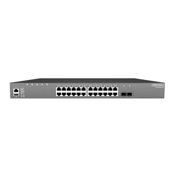
This manual describes each specific component, or related components, together with their installation requirements and procedures in each chapter. To understand Components each component in detail, refer to the relevant section. Figure 1: Switch Front Panels ECS4620-28T ECS4620-28T-DC ECS4620-28P ECS4620-28F ECS4620-28F-DC... - Page 13 Chapter 1 | Switch Description Overview 10/100/1000BASE-T RJ-45 Ports The switch contains 24/48 RJ-45 ports that support 10/100/1000BASE-T copper links to other devices. The ports on the ECS4620-28P and ECS4620-52P also support PoE+ connections. For more information, see “How to Connect to Twisted- Pair Copper Ports”...
-
Page 14: Figure 2: Rear Panel
Chapter 1 | Switch Description Overview Console Port The RJ-45 connector on the front panel labeled “Console” provides an out-of-band serial connection to a terminal or a PC running terminal emulation software. The port can be used for performing switch monitoring and configuration. For more information, see “How to Connect to the Console Port”... -
Page 15: Key Technical Specifications
32 IP interfaces 1023 multicast groups AC Input Power ECS4620-28T: 100 to 240 V, 50-60 Hz, 1.5 A ECS4620-28P: 100 to 240 V, 50-60 Hz, 10 A ECS4620-28F: 100 to 240 V, 50-60 Hz, 2 A ECS4620-52T: 100 to 240 V, 50-60 Hz, 2 A... - Page 16 ECS4620-52T: 4.8 kg (10.58 lb) ECS4620-52P: 6.58 kg (14.51 lb) Size (W x D x H) ECS4620-28T/T-DC/P/F/F-DC: 44.0 x 31.5 x 4.4 cm (17.3 x 12.4 x 1.7 in.) ECS4620-52T/P: 44.0 x 39.1 x 4.4 cm (17.3 x 15.4 x 1.7 in.) Temperature Operating: 0°...
-
Page 17: Installation Overview
ECS4620-28T, ECS4620-28T-DC, ECS4620-28P, ECS4620-28F, ECS4620-28F-DC, ECS4620-52T, or ECS4620-52P Switch ◆ AC Power Cord—either US, Continental Europe or UK ◆ DC connector plug (ECS4620-28T-DC and ECS4620-28F-DC only) ◆ Rack Mounting Kit — includes two brackets and eight screws ◆ Four adhesive foot pads ◆... -
Page 18: Switch Installation Tasks
Chapter 2 | Installation Overview Switch Installation Tasks Switch Installation Tasks Follow these tasks to install the switch in your network. For full details on each task, go to the relevant chapter or section by clicking on the link. Caution: Before installing your switch, first review all the safety statements and guidelines in the Regulatory and Safety Information document. -
Page 19: Figure 4: Connecting Ac Power
Chapter 2 | Installation Overview Switch Installation Tasks Task 3 Ground the Switch and Power On Connect a ground wire to the switch, and then use a AC power cable to connect the switch to a AC power source.. Go to the chapter “Power and Grounding”. -
Page 20: Figure 6: System Leds
Chapter 2 | Installation Overview Switch Installation Tasks Task 4 Verify Switch Operation Verify basic switch operation by checking the system LEDs. When operating normally, the Power and Diag LEDs should both be on green. If either of these LEDs are on amber, see “Diagnosing LED Indicators”... -
Page 21: Figure 7: Console Port
Chapter 2 | Installation Overview Switch Installation Tasks Figure 7: Console Port Connect console cable to switch’s Console port. Connect console cable to PC’s DB-9 COM port. For information on initial switch configuration: Refer to the CLI Reference Guide. Task 6 Install Transceivers and Connect Cables Install SFP/SFP+ transceivers and connect network cables to port interfaces: ◆... -
Page 22: Figure 8: Making A Connection To An Rj-45 Port
Chapter 2 | Installation Overview Switch Installation Tasks Go to the chapter “Port Connections” Figure 8: Making a Connection to an RJ-45 Port 10/100/1000BASE-T RJ-45 Port. Twisted-pair Cable with RJ-45 Plug. – 22 –... -
Page 23: Switch Chassis
Switch Chassis The switch is designed to be installed in a standard 19-inch equipment rack. Before continuing with switch installation, first review the general guidelines and switch cooling requirements in this chapter. This chapter includes these sections: ◆ “General Installation Guidelines” on page 23 ◆... -
Page 24: Switch Cooling Requirements
Chapter 3 | Switch Chassis Switch Cooling Requirements ◆ Make sure that the unit is connected to a separate grounded power outlet and is powered from an independent circuit breaker. As with any equipment, using a filter or surge suppressor is recommended. Verify that the external AC power requirements for the switch can be met as listed under “AC Power Supply Specifications”... -
Page 25: Rack Cooling
Chapter 3 | Switch Chassis How to Install the Switch in a Rack The ECS4620-28T and ECS4620-28T-DC use a fanless cooling design. The following figure shows the convective airflow from the switch. Figure 10: Switch Cooling (ECS4620-28T/ECS4620-28T-DC) Rack Cooling When mounting the switch in an enclosed rack or cabinet, be sure to check the following guidelines to prevent overheating: ◆... -
Page 26: Rack-Mounting Items
Chapter 3 | Switch Chassis How to Install the Switch in a Rack ◆ Rack Planning: When installing equipment in a rack, first plan how units can be best arranged. Try to always mount the heaviest equipment at the bottom of the rack. -
Page 27: Figure 11: Attaching The Brackets
Chapter 3 | Switch Chassis How to Install the Switch in a Rack Figure 11: Attaching the Brackets Bracket Screws Rack Mounting Bracket Following your rack plan, mark the holes in the rack where the switch will be installed. One person should lift the switch into the rack so that it is aligned with the marked holes. -
Page 28: How To Install The Switch On A Shelf Or Desktop
Chapter 3 | Switch Chassis How to Install the Switch on a Shelf or Desktop How to Install the Switch on a Shelf or Desktop The switch can be installed on any flat surface such as a desktop or shelf. To mount the switch on a flat surface, follow these steps: Attach the four adhesive feet to the bottom of the first switch. -
Page 29: Optional Media Expansion Module
Chapter 3 | Switch Chassis Optional Media Expansion Module Optional Media Expansion Module The switches support an optional hot-swappable, dual-port 10G SFP+ media expansion module that installs in the rear of the switch chassis. The module’s SFP+ slots support standard 10G SFP+ transceivers. The 10GBASE transceivers operate at 10 Gbps full duplex with support for flow control. -
Page 30: Figure 15: Installing An Optional Module
Chapter 3 | Switch Chassis How to Install an Optional Media Expansion Module Figure 15: Installing an Optional Module Module Slot Media Expansion Module Holding the module level, guide it into the carrier rails on each side and gently push it all the way into the slot, ensuring that it firmly engages with the connector. -
Page 31: Power And Grounding
Power and Grounding This chapter focuses on how to connect power to the switch, grounding the chassis, and how to power-on the switch. This chapter includes this sections: ◆ “AC Power Supply” on page 31 ◆ “DC Power Supply” on page 32 ◆... -
Page 32: Dc Power Supply
RPS. DC Power Supply The ECS4620-28T-DC and ECS4620-28F-DC require power from an external DC power circuit that can provide 36 to 75 VDC. A DC terminal is located on the rear panel of the switch. The terminal is for connecting the DC power circuit. -
Page 33: Optional Redundant Power Supply
Chapter 4 | Power and Grounding Optional Redundant Power Supply Optional Redundant Power Supply The ECS4620-52P switch supports an optional redundant power supply (RPS) connection. The connector labeled “RPS” on the switch rear panel is for the optional RPS. Figure 18: Redundant Power Supply Connector RPS Connector Table 4: RPS Specifications Item... -
Page 34: How To Connect To Ac Power
Chapter 4 | Power and Grounding How to Connect to AC Power Before powering on the switch, ground the switch to earth as described below. Ensure that the rack on which the switch is to be mounted is properly grounded and in compliance with ETSI ETS 300 253. Ensure that there is a good electrical connection to the grounding point on the rack (no paint or isolating surface treatment). -
Page 35: How To Connect To Dc Power
Chapter 4 | Power and Grounding How to Connect to DC Power Insert the plug on the other end of the power cord directly into the AC input socket on the back of the switch. Note: If your country’s AC power outlet standards do not match the power plug of the included AC power cord, you will need to change the AC power cord. -
Page 36: Figure 21: Dc Plug Connections
Chapter 4 | Power and Grounding How to Connect to DC Power To connect the switch to a power source: Verify that the external DC power supply can provide 36 to 75 VDC, 3.82 A maximum. Prepare two wires for the DC power source. Use 10 to 18 AWG stranded copper wire. - Page 37 Chapter 4 | Power and Grounding How to Connect to DC Power Warning: If the power leads are plugged into the wrong holes, the power supply will not work properly and may damage the switch. Push each wire about half an inch into the opening on the plug, and tighten down the clamp screw securely.
-
Page 38: Port Connections
Port Connections This chapter focuses on making connections to switch network interfaces, including how to install optional transceivers, and details on network cable specifications. This chapter includes these sections: ◆ “Cable Labeling and Connection Records” on page 39 ◆ “Understanding the Port Status LEDs” on page 40 ◆... -
Page 39: Cable Labeling And Connection Records
Chapter 5 | Port Connections Cable Labeling and Connection Records Cable Labeling and Connection Records When planning a network installation, it is essential to label the opposing ends of cables and to record where each cable is connected. Doing so will enable you to easily locate inter-connected devices, isolate faults and change your topology without need for unnecessary time consumption. -
Page 40: Understanding The Port Status Leds
Chapter 5 | Port Connections Understanding the Port Status LEDs Understanding the Port Status LEDs The switch includes LED indicators for each port to indicate link status and network activity. The port LEDs are shown below and described in the following table. Figure 22: Port Status LEDs Port 1-50 Link/Activity LEDs Port 51-52 Link/Activity LEDs... -
Page 41: Figure 23: Inserting An Sfp/Sfp+ Transceiver Into A Slot
Chapter 5 | Port Connections How to Install an SFP/SFP+ Transceiver Note: SFP/SFP+ transceivers are hot-swappable. The switch does not need to be powered off before installing or removing a transceiver. Note: SFP/SFP+ transceivers are not provided in the switch package. To install an SFP/SFP+ transceiver, do the following: Consider network and cabling requirements to select an appropriate transceiver type that is also compatible with the switch transceiver support. -
Page 42: How To Connect To Twisted-Pair Copper Ports
Chapter 5 | Port Connections How to Connect to Twisted-Pair Copper Ports How to Connect to Twisted-Pair Copper Ports The RJ-45 ports on the switch support automatic MDI/MDI-X pinout configuration, which enables you to use standard straight-through twisted-pair cables to connect to any other network device (PCs, servers, switches, routers, or hubs). -
Page 43: 1000Base-T Assignments
Chapter 5 | Port Connections How to Connect to Twisted-Pair Copper Ports Figure 24: RJ-45 Connector RJ-45 Pin Numbers Table 7: 10/100BASE-TX MDI and MDI-X Port Pinouts MDI-X Signal Name MDI Signal Name Transmit Data plus (TD+) Receive Data plus (RD+) -52V power (Negative V GND (Positive V port... -
Page 44: Power-Over-Ethernet
Chapter 5 | Port Connections How to Connect to Twisted-Pair Copper Ports Table 8: 1000BASE-T MDI and MDI-X Port Pinouts (Continued) MDI Signal Name MDI-X Signal Name Bi-directional Pair B Plus (BI_DB+) Bi-directional Pair A Plus (BI_DA+) GND (Positive V -52V power (Negative V port port... -
Page 45: Connection Procedure
Chapter 5 | Port Connections How to Connect to Twisted-Pair Copper Ports For each attached PoE-compliant device, the switch automatically senses the load and dynamically supplies the required power. The switch delivers power to a device using the wire pairs in UTP or STP cable. Connection Procedure Follow these steps to connect cables to 1000BASE-T RJ-45 twisted-pair copper ports. -
Page 46: How To Connect To Sfp/Sfp+ Fiber Optic Ports
Chapter 5 | Port Connections How to Connect to SFP/SFP+ Fiber Optic Ports How to Connect to SFP/SFP+ Fiber Optic Ports The switch provides slots for SFP+ or SFP-compliant fiber-optic transceivers. Note that all 10G SFP+ fiber optic ports operate at 10 Gbps full duplex. All 1000BASE fiber optic ports operate at 1 Gbps full duplex. -
Page 47: Connection Procedure
Chapter 5 | Port Connections How to Connect to SFP/SFP+ Fiber Optic Ports Connection Procedure Follow these steps to connect cables to SFP/SFP+ transceiver ports. Warning: This switch uses lasers to transmit signals over fiber optic cable. The lasers are compliant with the requirements of a Class 1 Laser Product and are inherently eye safe in normal operation. -
Page 48: Making 10 Gbps Dac Connections
Chapter 5 | Port Connections Making 10 Gbps DAC Connections Making 10 Gbps DAC Connections Direct Attach Cable (DAC) is a method of connecting two SFP+ interfaces without using optics and fiber cable. A fixed length of twinax copper cable is terminated at each end with physically-compliant SFP+ transceivers that do not include all their normal electronic and optical components. -
Page 49: Figure 27: Making Stack Connections
Chapter 5 | Port Connections Connecting Switches in a Stack When the stack is initially powered on, the Master unit is designated as unit 1 for a ring topology. For a line topology, the stack is simply numbered from top to bottom, with the first unit in the stack designated at unit 1. -
Page 50: Switch Management
Switch Management Both switches include a management agent that allows you to configure or monitor the switch using its embedded management software. To manage the switch, you can make a direct connection to the console port (out-of-band), or you can manage it through a network connection (in-band) using Telnet, Secure Shell (SSH), a web browser, or SNMP-based network management software. -
Page 51: Understanding The System Status Leds
Chapter 6 | Switch Management Understanding the System Status LEDs Understanding the System Status LEDs The switch includes a display panel of key system LED indicators. The LEDs, which are located on the front panel, are shown below and described in the following table. -
Page 52: How To Connect To The Console Port
Chapter 6 | Switch Management How to Connect to the Console Port How to Connect to the Console Port The RJ-45 Console port on the front panel of the switch is used to connect a console device to the switch for out-of-band console configuration. The console device can be a PC or workstation running a VT-100 terminal emulator, or a VT-100 terminal. - Page 53 Chapter 6 | Switch Management How to Connect to the Console Port ◆ Data bits—8 ◆ Flow control—None Follow these steps to connect to the Console port: Connect one end of the included RJ-45 to DB-9 serial cable to a DB-9 COM port connector on the management PC.
- Page 54 Chapter 6 | Switch Management How to Connect to the Console Port Note that the guest default user login will only allow a user to view switch parameter data. For a detailed description of connecting to the console and using the switch’s command line interface (CLI), refer to the CLI Reference Guide.
-
Page 55: A Troubleshooting
Troubleshooting Diagnosing LED Indicators Table 13: Troubleshooting Chart Symptom Action ◆ Power LED is Off Check connections between the switch, the power cord, and the AC power outlet. ◆ Check the AC power outlet is supplying 110-240 VAC. ◆ Contact your dealer for assistance. ◆... -
Page 56: Power And Cooling Problems
Chapter A | Troubleshooting Power and Cooling Problems Power and Cooling Problems If a power indicator does not turn on when the power cord is plugged in, you may have a problem with the power outlet, power cord, or internal power supply. However, if the switch shuts down after operating for a continuous period, check for loose power connections, power losses or surges at the power outlet. -
Page 57: Index
Index Numerics indicators, LED installation 10 Mbps collision domain power requirements 10 Mbps connectivity rules site requirements 10/100 PIN assignments installation troubleshooting 1000BASE fiber cable lengths introduction 1000BASE-T PIN assignments 10BASE-T cable lengths 10GBASE fiber cable lengths laser safety LED indicators DIAG port adhesive feet, attaching... - Page 58 Index web-based management – 58 –...
- Page 59 The Declaration of Conformity (DoC) can be obtained from www.edge-core.com -> support -> download -> declarations & certifications. ECS4620 Series E112016-AP-R05 150200000918A R05...
Need help?
Do you have a question about the ECS4620-28T and is the answer not in the manual?
Questions and answers